Rotary Expander
Sleiman; Tony ; et al.
U.S. patent application number 16/078958 was filed with the patent office on 2019-02-14 for rotary expander. The applicant listed for this patent is Vengeance Power Inc.. Invention is credited to Andre Sarkis Laba, Jessie Joseph Laba, Buck Sleiman, Tony Sleiman.
| Application Number | 20190048720 16/078958 |
| Document ID | / |
| Family ID | 59684648 |
| Filed Date | 2019-02-14 |


| United States Patent Application | 20190048720 |
| Kind Code | A1 |
| Sleiman; Tony ; et al. | February 14, 2019 |
ROTARY EXPANDER
Abstract
An improvement to an expander is disclosed. The expander is of the type that has vanes that extend and retract from a rotor body during rotation and create chambers that increase and decrease in size. The improvement comprises, for each vane, for each vane, a pivot axis orientated parallel to the rotational axis and about which said each vane pivots between the extended and retracted positions.
| Inventors: | Sleiman; Tony; (Windsor, CA) ; Sleiman; Buck; (Tecumseh, CA) ; Laba; Andre Sarkis; (Windsor, CA) ; Laba; Jessie Joseph; (Windsor, CA) | ||||||||||
| Applicant: |
|
||||||||||
|---|---|---|---|---|---|---|---|---|---|---|---|
| Family ID: | 59684648 | ||||||||||
| Appl. No.: | 16/078958 | ||||||||||
| Filed: | February 23, 2017 | ||||||||||
| PCT Filed: | February 23, 2017 | ||||||||||
| PCT NO: | PCT/CA2017/050223 | ||||||||||
| 371 Date: | August 22, 2018 |
Related U.S. Patent Documents
| Application Number | Filing Date | Patent Number | ||
|---|---|---|---|---|
| 62299046 | Feb 24, 2016 | |||
| Current U.S. Class: | 1/1 |
| Current CPC Class: | F01C 1/46 20130101; F01C 21/0881 20130101; F01C 21/08 20130101; F01C 1/44 20130101; F01C 19/02 20130101 |
| International Class: | F01C 1/46 20060101 F01C001/46; F01C 19/02 20060101 F01C019/02; F01C 21/08 20060101 F01C021/08 |
Claims
1. An improved expander of the type that is used to extract power from a supply of pressurized fluid and that includes: a housing: having a rotation axis; defining a hollow interior having an annular surface orientated parallel to the rotation axis and through which the rotation axis extends; and defining one or more ports which extend through the housing to the interior; a rotor mounted in the housing for rotation about the rotation axis, the rotor having a body having an outer tubular surface, the tubular surface having defined therein a plurality of voids; for each of the voids of the plurality, a vane, the vane: having a seal defining a tip of the vane; being mounted in the void for which it is provided for movement between a retracted position and an extended position; and being adapted such that, upon rotation of the rotor in the housing, movement of the vane between the extended and retracted positions causes the tip seal to sweep the annular surface; control means for controlling movement of the vanes and access to the ports such that the vanes create chambers which increase in volume when in communication with the source of pressurized fluid, the improvement comprising: for each vane, a pivot axis orientated parallel to the rotational axis and about which said each vane pivots between the extended and retracted positions.
2. The expander according to claim 1, wherein the vane terminates in a pintle and the pivot axis is defined by a socket formed in the body in which the pintle is mounted for rotational movement.
3. The expander according to claim 1, wherein the void is defined at least in part by an arcuate slot.
4. The expander according to claim 1, wherein the body is cylindrical and disposed in offset relation to the interior.
5. The expander according to claim 1, wherein the annular surface and the tubular surface are both oval and the body is centered in the interior.
6. The expander according to claim 1, wherein the control means comprises springs which bias the vanes for movement towards the extended positions.
7. The expander according to claim 1, wherein the rotor has a pair of end seals disposed axially apart from one another and defining, in combination with the tubular surface, the annular surface and the tip seal, the chambers.
8. The expander according to claim 7, wherein the end seals are defined in part by body seals carried by and spring mounted to the body and in part by vane seals carried by and spring mounted to the vanes.
Description
FIELD
[0001] The invention relates to the field of rotary expanders.
BACKGROUND
[0002] Rotary expanders are well known. Known rotary expanders are either relatively expensive to manufacture, relatively inefficient or relatively expensive to maintain.
SUMMARY OF THE INVENTION
[0003] Forming one aspect of the invention is an improvement to an expander of the type that is used to extract power from a supply of pressurized fluid and that includes: a housing, a rotor and control means. The housing: has a rotation axis; defines a hollow interior having an annular surface orientated parallel to the rotation axis and through which the rotation axis extends; and defines one or more ports which extend through the housing to the interior. The rotor is mounted in the housing for rotation about the rotation axis and has a body and vanes. The body has an outer tubular surface, the tubular surface having defined therein a plurality of voids. The vanes are provided one for each of the voids. Each vane: has a seal defining a tip of the vane; is mounted in the void for which it is provided for movement between a retracted position and an extended position; and is adapted such that, upon rotation of the rotor in the housing, movement of the vane between the extended and retracted positions causes the tip seal to sweep the annular surface. The control means is for controlling movement of the vanes and access to the ports such that the vanes create chambers which increase in volume when in communication with the source of pressurized fluid.
[0004] The improvement comprises: for each vane, a pivot axis orientated parallel to the rotational axis and about which said each vane pivots between the extended and retracted positions.
[0005] Advantages, features and characteristics of the present invention will become apparent to persons of ordinary skill upon review of the following detailed description, with reference to the accompanying drawings, the latter being briefly described hereinbelow.
BRIEF DESCRIPTION OF THE DRAWINGS
[0006] FIG. 1 is a perspective view of an expander according to an exemplary embodiment of the invention
[0007] FIG. 2 is a view similar to FIG. 1 with a portion removed for clarity;
[0008] FIG. 3 is a view of the structure of FIG. 2 from another vantage point;
[0009] FIG. 4 is a view similar to FIG. 3 with a further portion removed and partially exploded, for clarity
[0010] FIG. 5 is a view of a portion of the structure of FIG. 3;
[0011] FIG. 6A is a cross sectional, partially schematic view of an expander according to another exemplary embodiment of the invention;
[0012] FIG. 6B is a view of the structure of FIG. 6A in another position;
[0013] FIG. 6C is view of the structure of FIG. 6A in yet another position;
[0014] FIG. 7 is a view similar to FIG. 6A showing, in partially schematic cross-section, an expander according to yet another embodiment;
[0015] FIG. 8 is a view of another embodiment of the structure of encircled area 8 of FIG. 4; and
[0016] FIG. 9 is a view similar to FIG. 6A of another exemplary embodiment.
DETAILED DESCRIPTION
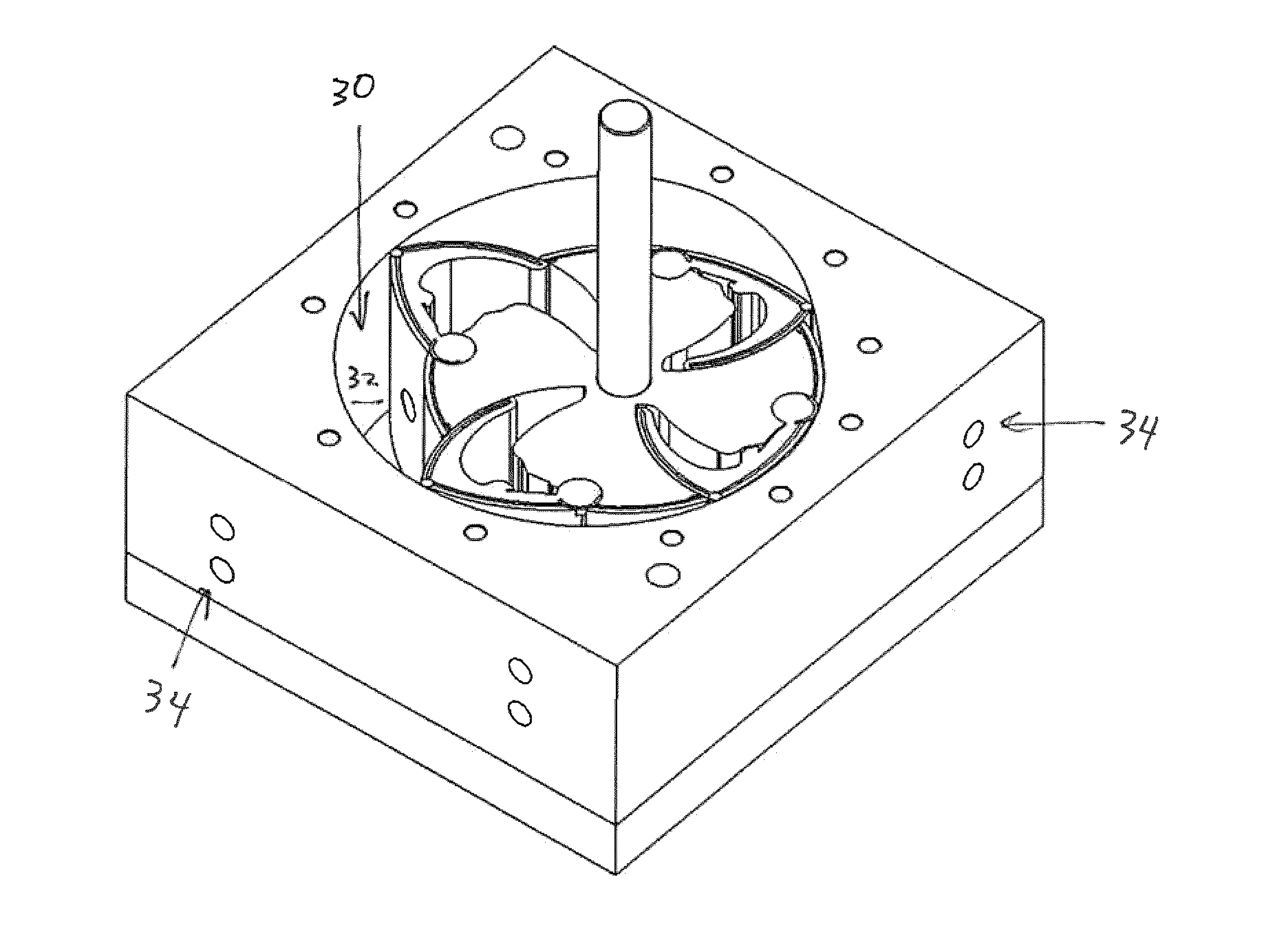
[0017] An expander 20 according to an exemplary embodiment of the invention is illustrated in FIG. 1 and will be understood, upon review of FIG. 1-FIG. 5, to include a housing 22, a rotor 24, control means 26 and end seals 28.
[0018] The housing will be understood to: have a rotation axis R-R; define a hollow interior 30 having an annular [generally oval] surface 32 orientated parallel to the rotation axis and through which the rotation axis extends; define one or more ports 34 which extend through the housing to the interior; and be defined by a tubular block 36 disposed between a pair of end plates 37.
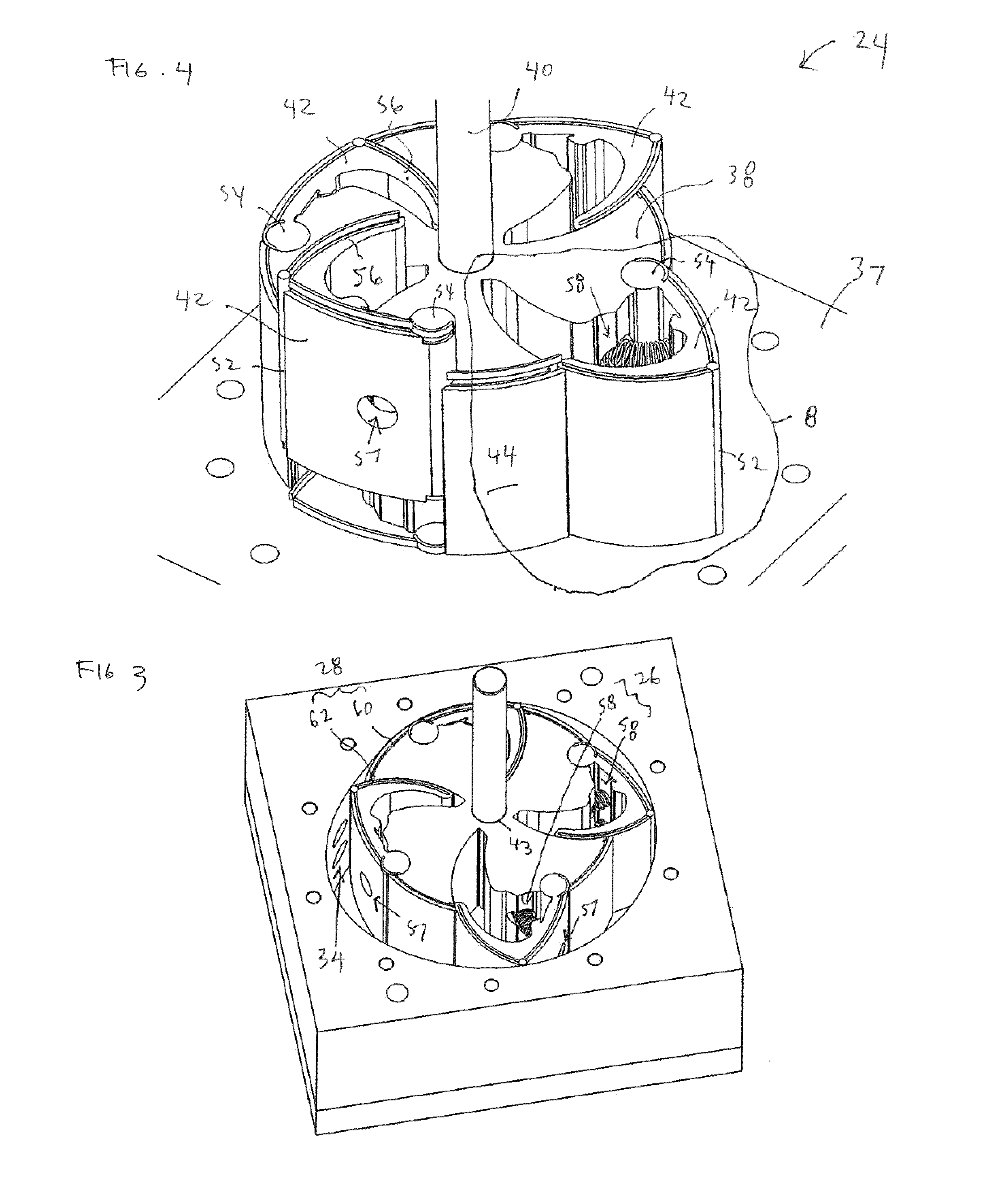
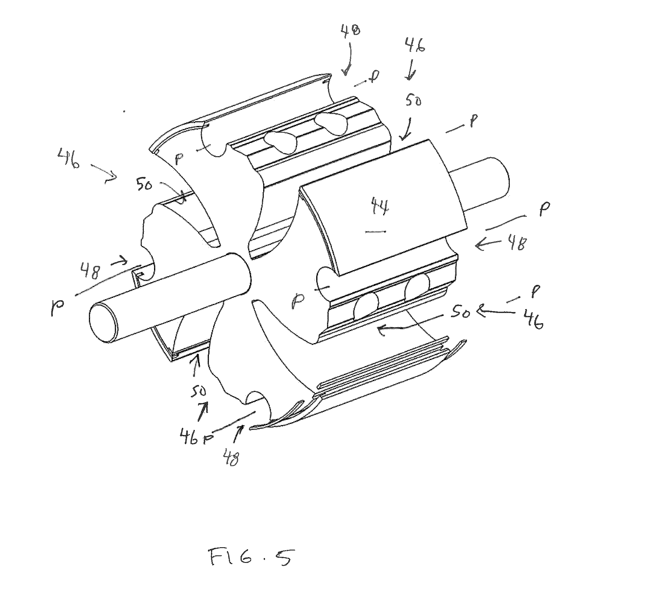
[0019] The rotor will be seen to be disposed in the interior and to include a body 38, a shaft 40 and vanes 42. This body will seen to be a generally cylindrical metal structure suitable for construction with wire EDM and drilling and to have a central bore 43 and an outer tubular surface 44, the tubular surface having defined therein a plurality of voids 46 and, associated with each void, a respective socket 48, each void being defined in part by an arcuate slot 50 and each socket defining a respective pivot axis P-P. The shaft passes through the bore. The vanes are provided one for each of the voids. Each vane has a seal 52 defining a tip of the vane, terminates in a pintle 54 which is mounted in the associated socket for rotational movement, as discussed further below, and includes an arcuate slider 56. Each vane further has vents 57 defined therein.
[0020] The control means will be seen to include springs 58.
[0021] The end seals are defined in part by body seals 60 carried by and spring mounted to the body and in part by vane seals 62 carried by and spring mounted to the vanes, all to project to and seal against the end plates. As best indicated by FIG. 4, the seals 60,62 in the exemplary embodiment are spring-mounted within slots provided in the vanes and body.
[0022] In use, it will be understood that the foregoing structure provides the functionality normally associated with an expander, namely, pressurized fluid is introduced into the interior through the ports, thus creating force on the trailing edges of the vanes which causes the rotor to turn. The control means controls movement of the vanes and access to the ports such that the vanes create chambers which increase in volume when in communication with the source of fluid at high pressure. The creation of a chamber that increases in volume when in communication with the source of pressurized fluid is best seen in the schematic views of the alternate expander of FIGS. 6A-6C, wherein a single vane is enumerated, for clarity, a chamber is seen to be created as the vane nears the port, as per the sequence of FIG. 6A, 6B, and the chamber C will be seen to increase in volume in the sequence of FIG. 6B, 6C.
[0023] However, tests have been carried out which demonstrate advantages associated with the design. A prototype similar to FIG. 1 was built using small wire EDM and CNC milling machines and produced 60 ft-lbs of stall torque with 90 psig compressed air. The accumulated run time of the prototype to date is over 100 hours of intermittent testing without any lubrication. Inspection of the vanes showed little wear with no adverse effects on the surrounding housing surfaces.
[0024] Without intending to be bound by theory, various of the advantages are believed to be attributable as follows: [0025] the force borne by the vane is transmitted to the hinged socket at the periphery of the rotor in a mostly perpendicular and highly favorable direction to the center of the shaft [0026] relatively high working pressures are tolerated by the robust structure of the vanes, which therefore remain true, thereby avoiding undue friction and wear [0027] the pintle/socket joint allows for relatively low friction movement of the vane between the extended and retracted position [0028] as the fluid expands and the pressure drops, the exposed surface area of the vane increases and the length of the torque lever increases, boosting efficiency [0029] pressure-induced force driving the leading faces of adjacent vanes back into the rotor, thus opening up a blow-by window, are negated by vents 57 on the leading face side, equalizing pressure within the rotor chambers and thereby preventing the vanes from being forced away from the block and back into the rotor body prematurely
[0030] Variations on the geometry are possible.
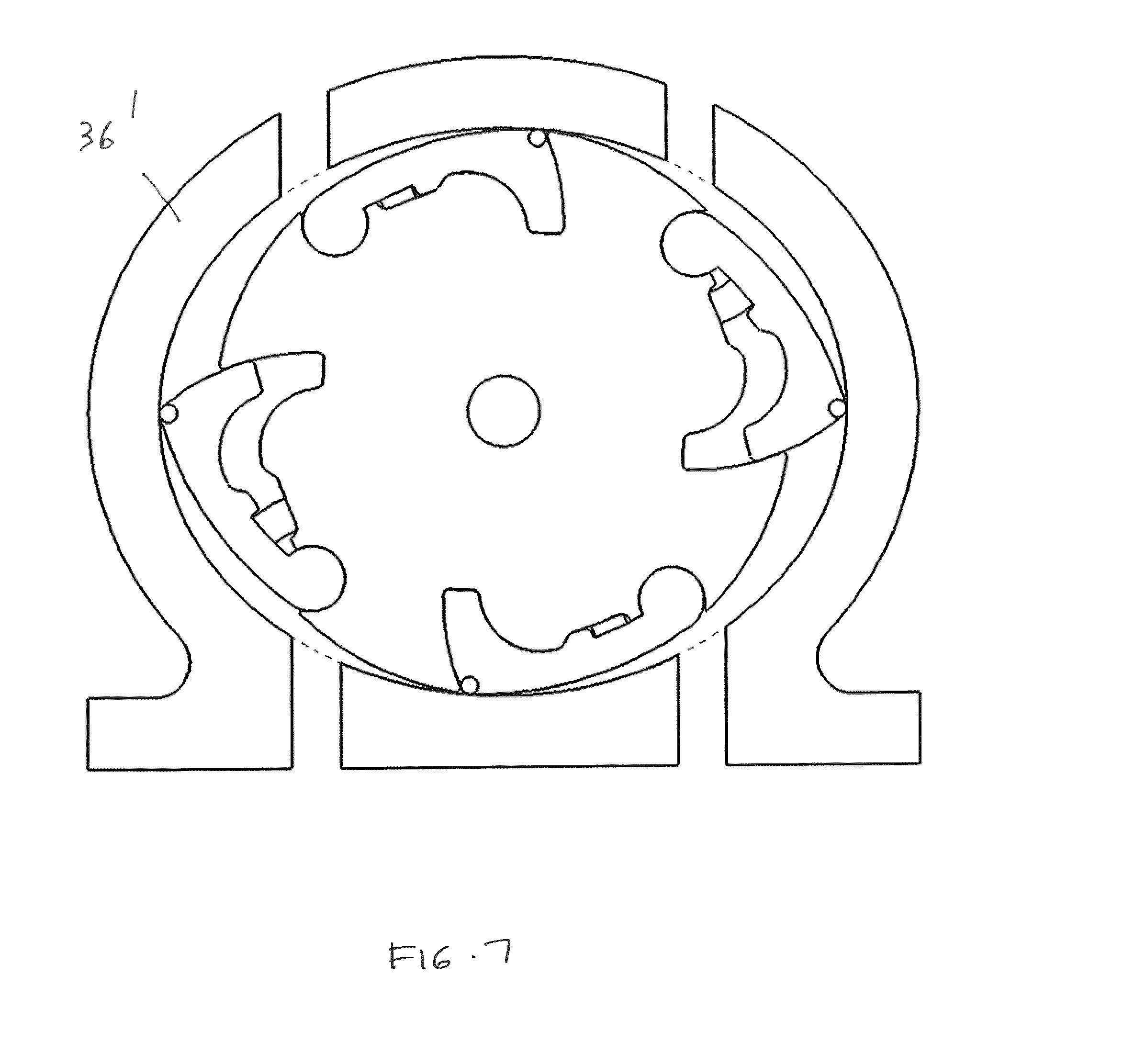
[0031] For example, the annular surface and the tubular surface can both be oval, with the rotor centered in the interior. An embodiment with a modified block 36' to achieve this is shown in FIG. 7. The modified block 36' also shows that the number of ports can be adjusted routinely by persons of ordinary skill in the art.
[0032] As well, a large range of customized volumetric expansion ratios can be achieved using readily available metered inlet controls without altering the base design.
[0033] Moreover, whereas springs are shown to bias the movement of the vanes at low speeds and startup, this is not necessary: there are many viable ways to control the vane movement such as magnets 64 as shown in FIG. 8 which repel vanes 42 from the body 38. Compressed gas and cams/rollers, not shown, can also be used.
[0034] Further, whereas in the exemplary embodiment, no lubrication is provided, such that the seals constitute sacrificial wear components, numerous lubricants can be employed including wet lubricants (oils) and dry lubricants (graphite, bronze, molybdenum disulfide, etc.) to increase life. Similarly, the end seals are not essential and could be removed in some applications.
[0035] As well, to reduce friction, wear and mechanical stress, axle-supported bearings can be provided at the ends of the sockets, not shown. Bearings can also be provided to facilitate movement of the sliders, as indicated by bearings 66 in FIG. 9. FIG. 9 also shows that the annular surface can be cylindrical, which has advantages in terms of machining.
[0036] Yet further, the expander can run in constant pressure mode like a hydraulic motor providing maximum torque at lowest speeds. This can be used as a safety fall-back, low expansion mode with full torque at low speed should the control means fail.
[0037] Accordingly, the invention should be understood to be limited only by the accompanying claims, purposively construed.
* * * * *
D00000
D00001
D00002
D00003
D00004
D00005
D00006
D00007
D00008
D00009
XML
uspto.report is an independent third-party trademark research tool that is not affiliated, endorsed, or sponsored by the United States Patent and Trademark Office (USPTO) or any other governmental organization. The information provided by uspto.report is based on publicly available data at the time of writing and is intended for informational purposes only.
While we strive to provide accurate and up-to-date information, we do not guarantee the accuracy, completeness, reliability, or suitability of the information displayed on this site. The use of this site is at your own risk. Any reliance you place on such information is therefore strictly at your own risk.
All official trademark data, including owner information, should be verified by visiting the official USPTO website at www.uspto.gov. This site is not intended to replace professional legal advice and should not be used as a substitute for consulting with a legal professional who is knowledgeable about trademark law.