Modular Well Pad Systems and Methods
Hardy; Paul ; et al.
U.S. patent application number 16/077249 was filed with the patent office on 2019-02-14 for modular well pad systems and methods. This patent application is currently assigned to Bantrel Co.. The applicant listed for this patent is Bantrel Co.. Invention is credited to Paul Hardy, Joe Overy.
| Application Number | 20190048699 16/077249 |
| Document ID | / |
| Family ID | 59563729 |
| Filed Date | 2019-02-14 |

| United States Patent Application | 20190048699 |
| Kind Code | A1 |
| Hardy; Paul ; et al. | February 14, 2019 |
Modular Well Pad Systems and Methods
Abstract
A modular well pad system, which includes an inlet module, a 2 well-pair module and a 3 well-pair module. The inlet module, one or more 2 well-pair modules and one or more 3 well-pair modules may be configured to build an interconnected well pad system for accommodating two to twelve well-pairs wherein standardized connections enable the 2 well-pair module and the 3 well-pair module to be coupled together, to the inlet module, another 2 well-pair module and/or another 3 well-pair module.
| Inventors: | Hardy; Paul; (Alberta, CA) ; Overy; Joe; (Alberta, CA) | ||||||||||
| Applicant: |
|
||||||||||
|---|---|---|---|---|---|---|---|---|---|---|---|
| Assignee: | Bantrel Co. Calgary AB |
||||||||||
| Family ID: | 59563729 | ||||||||||
| Appl. No.: | 16/077249 | ||||||||||
| Filed: | February 10, 2017 | ||||||||||
| PCT Filed: | February 10, 2017 | ||||||||||
| PCT NO: | PCT/IB2017/000188 | ||||||||||
| 371 Date: | August 10, 2018 |
Related U.S. Patent Documents
| Application Number | Filing Date | Patent Number | ||
|---|---|---|---|---|
| 62294418 | Feb 12, 2016 | |||
| Current U.S. Class: | 1/1 |
| Current CPC Class: | E21B 41/00 20130101; E21B 43/128 20130101; E21B 43/30 20130101; E21B 43/2406 20130101 |
| International Class: | E21B 43/30 20060101 E21B043/30; E21B 43/24 20060101 E21B043/24; E21B 43/12 20060101 E21B043/12 |
Claims
1. A modular well-pad system, comprising: an inlet module comprising a plurality of service lines, wherein one or more of the plurality of service lines is connected at one end of the inlet module to a central processing facility and the plurality of service lines is connectable at another end of the inlet module to a respective plurality of service lines connected to one end of a 2 well-pair module and a respective plurality of services lines connected to one end of a 3 well-pair module; at least one of the 2 well-pair module and the 3 well-pair module, wherein the plurality of service lines connected to the one end of the 2 well-pair module and the plurality of service lines connected to the one end of the 3 well-pair module are connectable to i) a respective plurality of service lines connected to another end of the 2 well-pair module or a respective plurality of service lines connected to another end of the 3 well-pair module, and ii) a respective plurality of service lines connected to another end of another 2 well-pair module and a respective plurality of service lines connected to another end of another 3 well-pair module and wherein the plurality of service lines connected to the another end of the 2 well-pair module and the plurality of service lines connected to the another end of 3 well-pair module are connectable to a respective plurality of service lines connected to one end of another 2 well-pair module and a respective plurality of service lines connected to one end of another 3 well-pair module; the 2 well-pair module connectable to two well pairs and the 3 well-pair module connectable to three well pairs, wherein each well pair represents an injection well and a production well.
2. The system of claim 1, further comprising four 3 well-pair modules.
3. The system of claim 1, further comprising two 3 well-pair modules and three 2 well-pair modules.
4. The system of claim 1, wherein the inlet module, the 2 well-pair module and the 3 well-pair module are transportable by truck.
5. The system of claim 1, wherein each plurality of service lines comprises a steam or high pressure water line, a natural gas line, an instrument control line, a production line, a casing gas line and a start-up fluid line.
6. The system of claim 5, wherein the production line includes one of emulsion, water, solution gas and oil.
7. The system of claim 5, wherein the instrument control line includes one of electricity and air.
8. The system of claim 5, wherein the production line, the casing gas line, the natural gas line and the steam or high pressure water line are connected at the one end of the inlet module to the central processing facility and the instrument control line and start-up fluid lines are connected to opposite sides of the inlet module.
9. The system of claim 5, wherein the 2 well-pair module and the 3 well-pair module each comprise another production line and another casing gas line connected at a production side of each respective 2 well-pair module and 3 well-pair module to each respective production well.
10. The system of claim 9, wherein the 2 well-pair module and the 3 well-pair module each comprise another natural gas line and another steam or high pressure water line connected at an injection side and the production side of each respective 2 well-pair module and 3 well-pair module to each respective injection well and each respective production well.
11. The system of claim 10, wherein the 2 well-pair module and the 3 well-pair module each comprise another start-up fluid line connected at the injection side of each respective 2 well-pair module and 3 well-pair module to each respective injection well.
12. The system of claim 6, further comprising an electric submersible pump positioned below each production well.
13. The system of claim 12, wherein the emulsion, water, solution gas and oil are each a single phase liquid product.
14. The system of claim 1, wherein each connection is standardized.
Description
CROSS-REFERENCE TO RELATED APPLICATIONS
[0001] The priority of U.S. Provisional Patent Application No. 62/294,418, filed Feb. 12, 2016, is hereby claimed and the specification thereof is incorporated herein by reference.
FIELD OF THE DISCLOSURE
[0002] The present disclosure generally relates to modular well pad systems and methods. More particularly, the present disclosure relates to a modular well pad system, which includes an inlet module, a 2 well-pair module and a 3 well-pair module. The inlet module, one or more 2 well-pair modules and one or more 3 well-pair modules may be configured to build an interconnected well pad system for accommodating two to twelve well-pairs wherein standardized connections enable the 2 well-pair module and the 3 well-pair module to be coupled together, to the inlet module, another 2 well-pair module and/or another 3 well-pair module.
BACKGROUND
[0003] Steam Assisted Gravity Drainage (SAGD) is a methodology of oil extraction where steam is injected into the underground oil reservoir through an injection well and bituminous product is collected though a production well. The steam is injected downhole to melt bitumen trapped within a sand layer, typically anywhere from 200 to 500 meters below grade. The resultant mixture of bitumen and water (hereinafter referred to as a production emulsion) flows up through the production well, potentially with some free gas, where a well pad and surface facilities handle the transfer of the production emulsion to a central processing facility (CPF). Because the production emulsion is a multiphase product, the liquid and gases are separated and sent to the CPF. Conventional SAGD well pads thus, require the use of separator vessels.
[0004] Conventional SAGD well-pads are often constructed in a way that allows for much of the construction and fabrication work to be performed offsite, in a more controlled environment, and then assembled on-site. Each well pad thus, may include multiple modules that can be shipped by highway on a flatbed trailer of a transport truck and then lowered or lifted into place for assembly on-site. Such modules, however, still lack the requisite standardization necessary to permit simple interconnectivity between the modules regardless of the module type, well pad location and design parameters. Moreover, the lack of simple interconnectivity also renders such modules significantly inflexible for expansion. As a result, conventional SAGD well pads remain highly customized and therefore, costly to construct.
BRIEF DESCRIPTION OF THE DRAWINGS
[0005] The present disclosure is described with reference to the accompanying drawings, in which like elements are referenced with like reference numbers, and in which:
[0006] FIG. 1 is a site plan illustrating one embodiment of a modular well-pad system comprising an inlet module, a 2 well-pair module and a 3 well-pair module for accommodating 5 well-pairs.
[0007] FIG. 2 is a schematic sectional view of the inlet module in FIG. 1 illustrating standardized connections to the inlet module.
[0008] FIG. 3 is a schematic sectional view of the 2 well-pair module in FIG. 1 illustrating standardized connections to the 2 well-pair module.
[0009] FIG. 4 is a schematic sectional view of the 3 well-pair module in FIG. 1 illustrating standardized connections to the 3 well-pair module.
DETAILED DESCRIPTION OF THE ILLUSTRATIVE EMBODIMENTS
[0010] The subject matter of the present disclosure is described with specificity, however, the description itself is not intended to limit the scope of the disclosure. The subject matter thus, might also be embodied in other ways, to include different structures, steps and/or combinations similar to and/or fewer than those described herein, in conjunction with other present or future technologies. Moreover, although the term "step" may be used herein to describe different elements of methods employed, the term should not be interpreted as implying any particular order among or between various steps herein disclosed unless otherwise expressly limited by the description to a particular order. Other features and advantages of the disclosed embodiments will be or will become apparent to one of ordinary skill in the art upon examination of the following figures and detailed description. It is intended that all such additional features and advantages be included within the scope of the disclosed embodiments. Further, the illustrated figures are only exemplary and are not intended to assert or imply any limitation with regard to the environment, architecture, design, or process in which different embodiments may be implemented.
[0011] The pressure profile for a well-pad cannot be standardized because the location of each well pad in relation to the CPF is unique to each project. Similarly, the topography along the right of way is also unique to each project. Due to these factors, the selection of some well-pad design parameters (e.g. single phase pipelines vs multi-phase pipelines; separation on or off the well pad; pipeline size (internal diameter); and pumping configuration--pumps in series, multi-phase pumps), based on costs, cannot be easily made using a standardized design. As used herein, the terms "pipeline" and "pipelines" may also be referred to as piping, line or lines.
[0012] Other parameters of the well pad design and its production (engineering, procurement, fabrication, installation and construction), however, may be standardized to achieve substantial production savings. The modular well pad described herein employs carefully controlled reservoir pressure and temperature conditions along with the use of submersible downhole pumps that produce a product with a single liquid phase, thereby eliminating the requirement for separator vessels and a costly gas pipeline back to the CPF. The modular well pad and its production may thus, be standardized by (i) removing separators (group and test) from the design by raising the product pressure to above the bubble point using electric submersible pumps (ESPs); (ii) providing an option to connect to a multi-phase pump to boost the pressure further if need be to remain a single phase (liquid) for the product; and iii) providing an option to connect to a separation building if required to enable two single phase pipelines (1 gas, 1 liquid emulsion) for the product.
[0013] Because the modular well-pad connections between modules are standardized, the modular well-pad allows for increased flexibility and repeatability without any additional engineering. Moreover, production costs for the modular well-pad are lowered because the modular well-pad is based on a design that: i) reduces the scope of a well-pad to the maximum possible extent without sacrificing life cycle cost; ii) reduces the scope of on-site field production using modularization; iii) reduces materials; and iv) provides options to enable the design to be customized.
[0014] The modular well-pad thus, overcomes one or more of the prior art disadvantages with an inlet module. a 2 well-pair module and a 3 well-pair module. The inlet module, one or more 2 well-pair modules and one or more 3 well-pair modules may be configured to build an interconnected well pad system for accommodating two to twelve well-pairs wherein standardized connections enable the 2 well-pair module and the 3 well-pair module to be coupled together, to the inlet module, another 2 well-pair module and/or another 3 well-pair module.
[0015] In one embodiment the present disclosure includes a modular well-pad system, comprising an inlet module comprising a plurality of service lines, wherein one or more of the plurality of service lines is connected at one end of the inlet module to a central processing facility and the plurality of service lines is connectable at another end of the inlet module to a respective plurality of service lines connected to one end of a 2 well-pair module and a respective plurality of services lines connected to one end of a 3 well-pair module; at least one of the 2 well-pair module and the 3 well-pair module, wherein the plurality of service lines connected to the one end of the 2 well-pair module and the plurality of service lines connected to the one end of the 3 well-pair module are connectable to i) a respective plurality of service lines connected to another end of the 2 well-pair module or a respective plurality of service lines connected to another end of the 3 well-pair module, and ii) a respective plurality of service lines connected to another end of another 2 well-pair module and a respective plurality of service lines connected to another end of another 3 well-pair module and wherein the plurality of service lines connected to the another end of the 2 well-pair module and the plurality of service lines connected to the another end of 3 well-pair module are connectable to a respective plurality of service lines connected to one end of another 2 well-pair module and a respective plurality of service lines connected to one end of another 3 well-pair module; the 2 well-pair module connectable to two well pairs and the 3 well-pair module connectable to three well pairs, wherein each well pair represents an injection well and a production well.
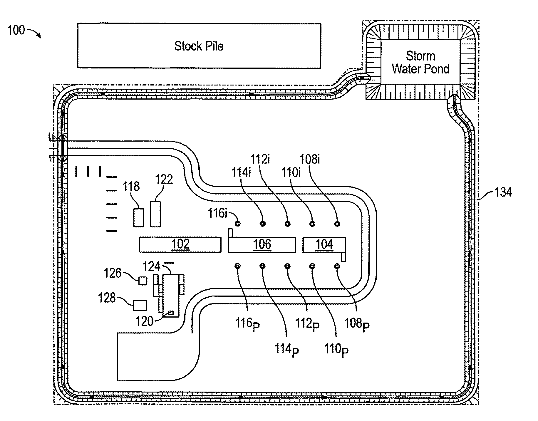
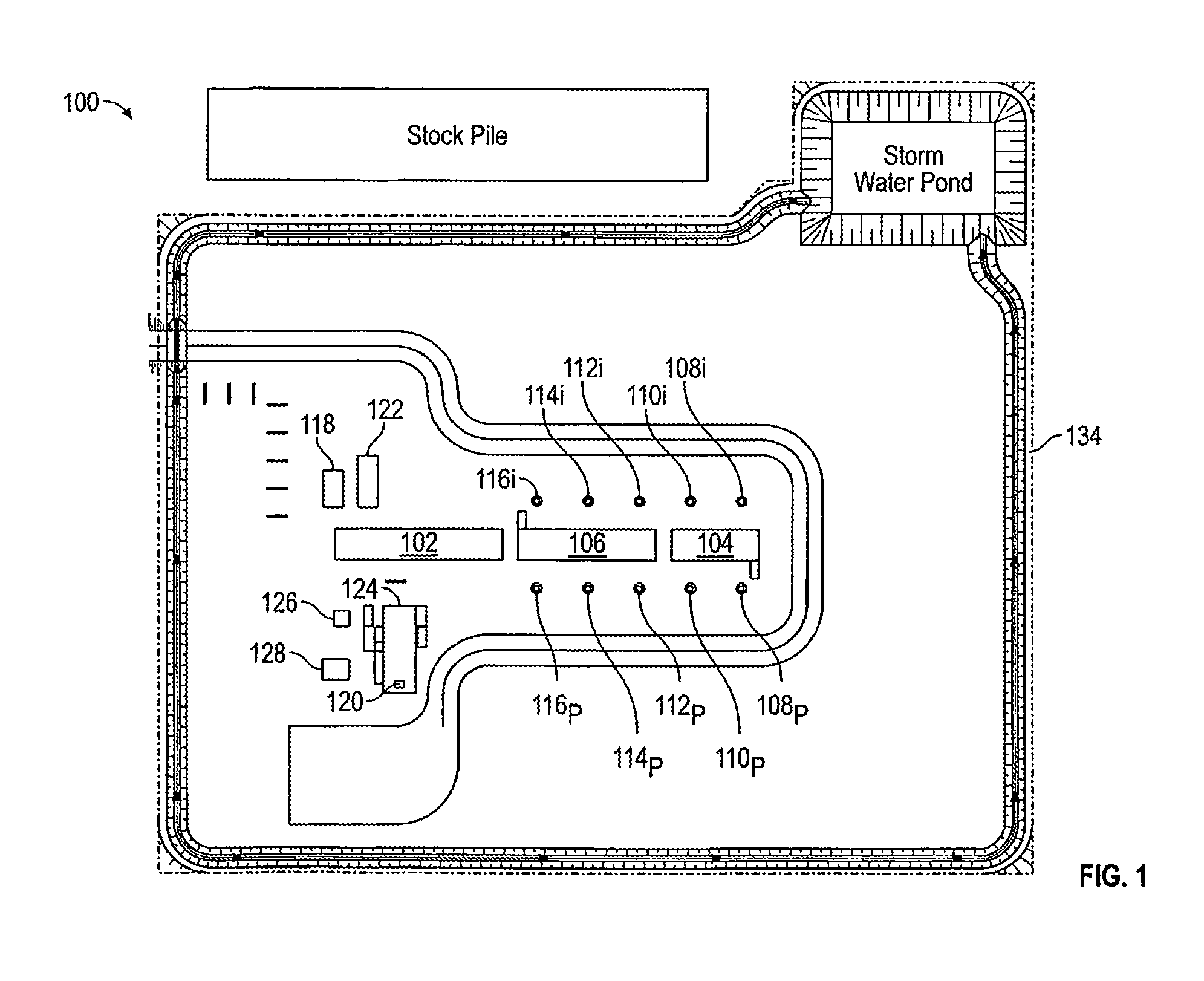
[0016] Referring now to FIG. 1, a site plan 100 illustrates one embodiment of a modular well-pad system comprising an inlet module 102, a 2 well-pair module 104 and a 3 well-pair module 106 for accommodating five well-pairs 108-116. Each well pair represents one production well (p) and one steam injection well (i). The modular well-pad system may also include various support structures. A natural gas heater 118 is used for heating the natural gas from the CPF in order to avoid the formation of condensation in the natural gas entering the inlet module 102. An instrument air package (consisting of compressor, dryer and receiver) 120 is used for providing the instrument air entering the inlet module 102 that controls the valves in each module. An optional start-up package 122 may be used for providing start-up fluid entering the inlet module 102 that supports the formation of a steam chamber below each injection well as part of the SAGD process. An electrical building 124 is used for transmitting power to i) each ESP below each production well; ii) each electrical heat tracing (EHT) panel for freeze protection on the piping in each module; and iii) general utilities (e.g. lighting) in each module. A stick built cable tray and pipe (not shown) connects the electrical building 124 to the inlet module 102. The electric building 124 also includes a pre-fabricated access platform and stairs (not shown). A pre-fabricated access platform and stairs may also be provided for each EHT panel. An ATCO transformer 126 is used for supplying power to the electrical building 124 and variable frequency drive (VFD) skids 128 are used for controlling the power to each ESP. A stock pile may be used for storing excess soil and a storm water pond may be used for collecting excess water runoff from the well-pad system.
[0017] The modular well-pad system is based on receiving a pre-drilled well-pad to rough grade with an installed power transformer 126. Each module is sized for highway transport and designed to be lowered onto piles from the bed of a transport vehicle so that the on-site use of cranes is no longer required. Because the modular well-pad system and its production is largely standardized, it is expandable from two well-pairs up to a maximum of twelve well-pairs within a well-pad boundary 134 using 2 and 3 well-pair modules that can be assembled in any configuration necessary to achieve the required count. Because module operating platforms are designed to mate closely field platforms or handrail construction is not required. Field installed stairways. however, can be provided on any module based on local construction and safety requirements.
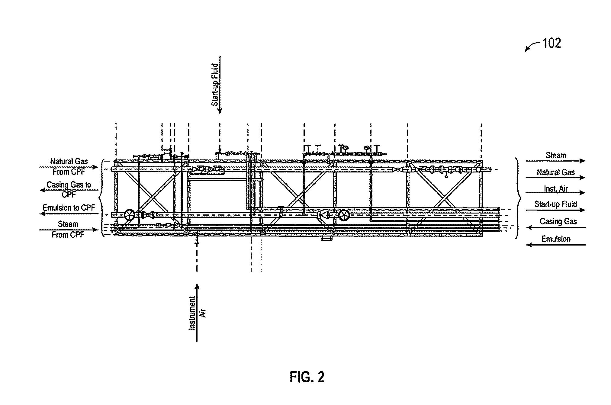
[0018] Referring now to FIG. 2, a schematic sectional view of the inlet module 102 in FIG. 1 illustrates standardized connections to the inlet module 102. The inlet module 102 functions as the interface between the interconnecting pipelines to and from the CPF and interconnecting pipelines from other support structures. An emulsion line and a casing gas line are connected to each end of the inlet module 102. Emulsion and casing gas produced by each production well (p) in the well-pairs 108-116 (FIG. 1) enter the inlet module 102 from the 2 well-pair module 104 or the 3 well-pair module 106 and exit the inlet module 102 to the CPF. A steam line and a natural gas line are also connected to each end of the inlet module 102. Steam and natural gas enter the inlet module 102 from the CPF and exit the inlet module 102 to the 2 well-pair module 104 or the 3 well-pair module 106. An instrument air-line and a start-up fluid line are connected on opposite sides of the inlet module 102 and at one end of the inlet module 102 that is connected to the 2 well-pair module 104 or the 3 well-pair module 106. Instrument air and start -up fluid enter the inlet module 102 from the instrument air package 120 and the start-up package 122, respectively, and exit the inlet module 102 to the 2 well-pair module 104 or the 3 well-pair module 106. The instrument air entering the inlet module 102 controls any valves in the inlet module 102 such as the emergency shutdown valves for the critical steam, emulsion, natural gas, casing gas, and start-up fluid lines at the well pad limits. The inlet module 102 also includes the required metering for process measurement of steam, emulsion, natural gas, casing gas, instrument air and start-up fluid lines (hereinafter collectively referred to as service lines) and regulatory purposes. A pre-fabricated metering system piping spool and steam pressure safety valve (PSV) piping spool (not shown) are connected to one side of the inlet module 102 on site. The inlet module 102 minimizes the spacing required for piping, mechanical and electrical connections. Standardized connections allow for mating-up between the service lines connected to the inlet module 102 and the respective service lines connected to the 2 well pair module 104 or the 3 well pair module 106. The standardized connections thus, allow for predictable connectivity in any conceivable well pad design. In any combination of the well-pad system modules, only one inlet module 102 is required.
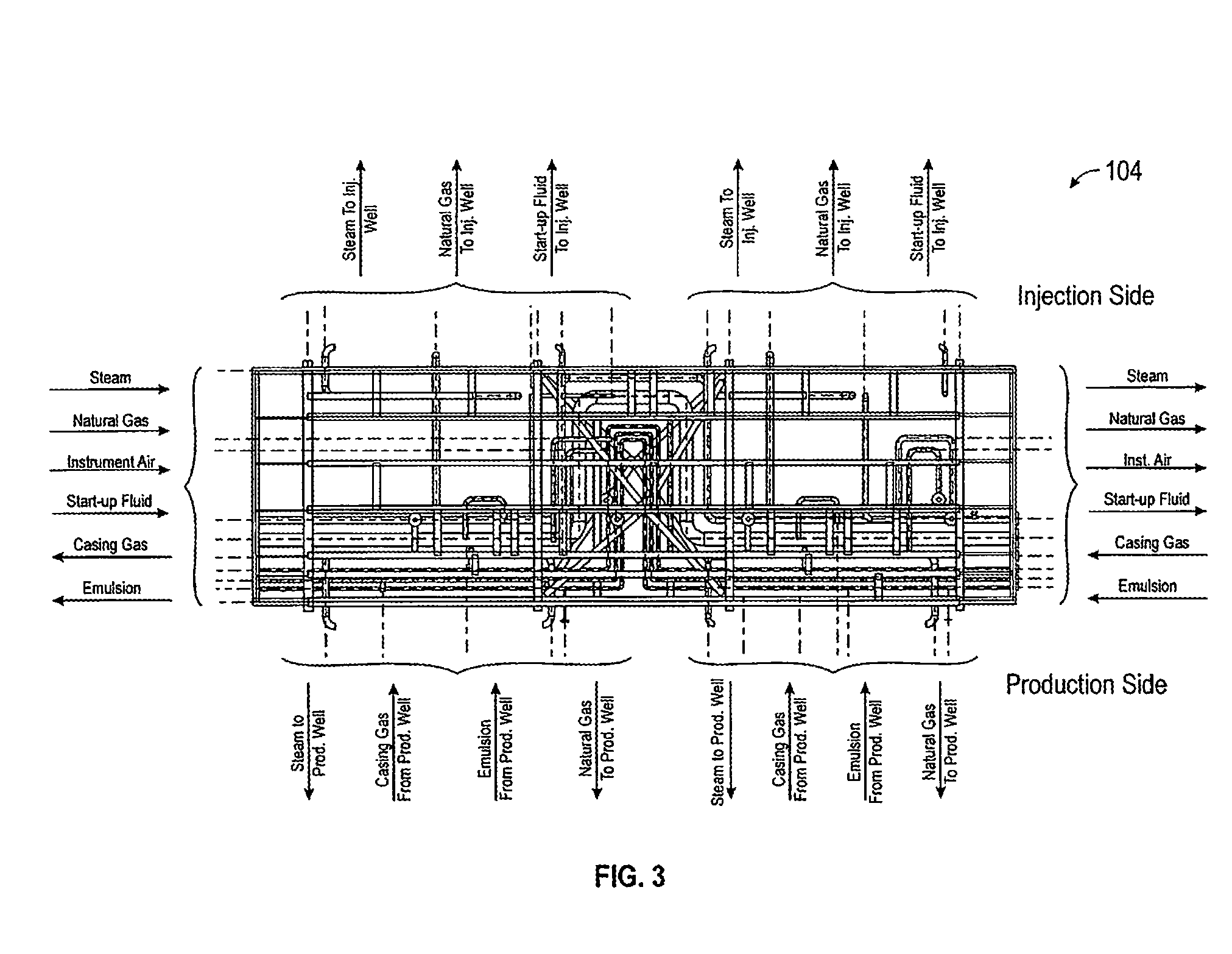
[0019] Referring now to FIG. 3, a schematic sectional view of the 2 well-pair module 104 in FIG. 1 illustrates standardized connections to the 2 well-pair module 104. An emulsion line and a casing gas line are connected to each end of the 2 well-pair module 104. Alternatively, an emulsion line and a casing gas line may be connected to only one end of the 2 well-pair module 104 when it is the last module on the end of a modular well-pad system. Emulsion and casing gas produced by each production well (p) in the well-pairs 108-116 (FIG. 1) enter the 2 well-pair module 104 from another 2 well-pair module 104, the 3 well-pair module 106 and/or another emulsion line and casing gas line connected to the production side of the 2 well-pair module 104 from each production well. The emulsion and casing gas exit the 2 well-pair module 104 to the inlet module 102, another 2 well-pair module 104 or the 3 well-pair module 106. A steam line, a natural gas line, an instrument-air line and a start-up fluid line are also connected to each end of the 2 well-pair module 104. Alternatively, a steam line, a natural gas line, an instrument-air line and a start-up fluid line may be connected to only one end of the 2 well-pair module 104 when it is the last module on the end of a modular well-pad system. Steam, natural gas, instrument air and start-up fluid enter the 2 well-pair module 104 from the inlet module 102, another 2 well-pair module 104 or the 3 well-pair module 106. The instrument air entering the 2 well-pair module 104 controls any valves in the 2 well-pair module 104 and exits the 2 well-pair module 104 to another 2 well-pair module 104 or the 3 well-pair module 106. Steam and natural gas exit the 2 well-pair module 104 to another 2 well-pair module 104, the 3 well-pair module 106 and/or another steam line and natural gas line connected to the injection side and the production side of the 2 well-pair module 104 from each respective injection well and production well. Steam is used to form a steam chamber below each injection well and each production well as part of the SAGD process. Natural gas is used as blanket gas for each injection well and each production well. Start-up fluid also exits the 2 well-pair module 104 to another 2 well-pair module 104, the 3 well-pair module 106 and/or another start-up fluid line connected to the injection side of the 2 well-pair module 104 from each respective injection well. The start-up fluid may be used to support the formation of a steam chamber below each injection well as part of the SAGD process. The 2 well-pair module 104 contains the process piping and controls necessary to supply steam to each injection well and receive emulsion from each production well. Each injection well and production well are connected to the 2 well-pair module 104 by a respective pre-fabricated piping spool (not shown), which includes swivel joints. The 2 well-pair module 104 minimizes the spacing required for piping, mechanical and electrical connections. Standardized connections allow for mating-up between the service lines connected to the 2 well-pair module 104 and the respective service lines connected to the inlet module 102, another 2 well-pair module 104 and/or the 3 well-pair module 106. The standardized connections allow for predictable connectivity in any conceivable well pad design. The 2 well pair module 104 may thus. be combined with the inlet module and the 3 well-par module 106 in any quantity or combination to achieve a modular well-pad system that can accommodate two to twelve well-pairs on a well pad. For example, seven well-pairs will contain a 3 well-pair module 106 and two 2 well-pair modules 104.
[0020] Referring now to FIG. 4, a schematic sectional view of the 3 well-pair module 106 in FIG. 1 illustrates standardized connections to the 3 well-pair module 106. An emulsion line and a casing gas line are connected to each end of the 3 well-pair module 106. Alternatively, an emulsion line and a casing gas line may be connected to only one end of the 3 well-pair module 106 when it is the last module on the end of a modular well-pad system. Emulsion and casing gas produced by each production well (p) in the well-pairs 108-116 (FIG. 1) enter the 3 well-pair module 106 from the 2 well-pair module 104, another 3 well-pair module 106 and/or another emulsion line and casing gas line connected to the production side of the 3 well-pair module 106 from each production well. The emulsion and casing gas exit the 3 well-pair module 106 to the inlet module 102, the 2 well-pair module 104 or another 3 well-pair module 106. A steam line, a natural gas line, an instrument-air line and a start-up fluid line are also connected to each end of the 3 well-pair module 106. Alternatively, a steam line, a natural gas line, an instrument-air line and a start-up fluid line may be connected to only one end of the 3 well-pair module 106 when it is the last module on the end of a modular well-pad system. Steam, natural gas, instrument air and start-up fluid enter the 3 well-pair module 106 from the inlet module 102, the 2 well-pair module 104 or another 3 well-pair module 106. The instrument air entering the 3 well-pair module 106 controls any valves in the 3 well-pair module 106 and exits the 3 well-pair module 106 to the 2 well-pair module 104 or another 3 well-pair module 106. Steam and natural gas exit the 3 well-pair module 106 to the 2 well-pair module 104, another 3 well-pair module 106 and/or another steam line and natural gas line connected to the injection side and the production side of the 3 well-pair module 106 from each respective injection well and production well. Steam is used to form a steam chamber below each injection well and each production well as part of the SAGD process. Natural gas is used as blanket gas for each injection well and each production well. Start-up fluid also exits the 3 well-pair module 106 to the 2 well-pair module 104, another 3 well-pair module 106 and/or another start-up fluid line connected to the injection side of the 3 well-pair module 106 from each respective injection well. The start-up fluid may be used to support the formation of a steam chamber below each injection well as part of the SAGD process. The 3 well-pair module 106 contains the process piping and controls necessary to supply steam to each injection well and receive emulsion from each production well. Each injection well and production well are connected to the 3 well-pair module 106 by a respective pre-fabricated piping spool (not shown), which includes swivel joints. The 3 well-pair module 106 minimizes the spacing required for piping, mechanical and electrical connections. Standardized connections allow for mating-up between the service lines connected to the 3 well-pair module 106 and the respective service lines connected to the inlet module 102, the 2 well-pair module 104 and/or another 3 well-pair module 106. The standardized connections allow for predictable connectivity in any conceivable well pad design. The 3 well pair module 106 may thus, be combined with the inlet module and the 2 well-par module 104 in any quantity or combination to achieve a modular well-pad system that can accommodate two to twelve well-pairs on a well pad. For example, seven well-pairs will contain a 3 well-pair module 106 and two 2 well-pair modules 104.
[0021] Those skilled in the art will appreciate that the inlet module 102, the 2 well-pair module 104 and the 3 well-pair module 106 may include many possible different internal configurations of piping, mechanical and electrical components. If, for example, these modules needed to support a water flood reservoir support design (high pressure water injection downhole), then each steam line would be replaced with high pressure water line (with suitable controls) and each emulsion line would be replaced with another reservoir production fluid line such as a water, solution gas or oil line. Suitable controls for these new lines may require electrical actuation in which the instrument-air line may be replaced with an electrical line. In these cases the piping may vary at the Christmas tree accordingly.
[0022] While the present disclosure has been described in connection with presently preferred embodiments, it will be understood by those skilled in the art that it is not intended to limit the disclosure to those embodiments. It is therefore, contemplated that various alternative embodiments and modifications may be made to the disclosed embodiments without departing from the spirit and scope of the disclosure defined by the appended claims and equivalents thereof.
* * * * *
D00000
D00001
D00002
D00003
D00004
XML
uspto.report is an independent third-party trademark research tool that is not affiliated, endorsed, or sponsored by the United States Patent and Trademark Office (USPTO) or any other governmental organization. The information provided by uspto.report is based on publicly available data at the time of writing and is intended for informational purposes only.
While we strive to provide accurate and up-to-date information, we do not guarantee the accuracy, completeness, reliability, or suitability of the information displayed on this site. The use of this site is at your own risk. Any reliance you place on such information is therefore strictly at your own risk.
All official trademark data, including owner information, should be verified by visiting the official USPTO website at www.uspto.gov. This site is not intended to replace professional legal advice and should not be used as a substitute for consulting with a legal professional who is knowledgeable about trademark law.