Unitary Actuator Valve For Downhole Operations
Kao; Conrad ; et al.
U.S. patent application number 15/671488 was filed with the patent office on 2019-02-14 for unitary actuator valve for downhole operations. This patent application is currently assigned to Baker Hughes, a GE company, LLC. The applicant listed for this patent is Anjani Achanta, Luke Alan Boyer, Shay Hetz, Jack Hudson, Conrad Kao, Joshua Raymond Snitkoff, John Patrick Speights, Eugene Stolboushkin. Invention is credited to Anjani Achanta, Luke Alan Boyer, Shay Hetz, Jack Hudson, Conrad Kao, Joshua Raymond Snitkoff, John Patrick Speights, Eugene Stolboushkin.
| Application Number | 20190048684 15/671488 |
| Document ID | / |
| Family ID | 65272457 |
| Filed Date | 2019-02-14 |


| United States Patent Application | 20190048684 |
| Kind Code | A1 |
| Kao; Conrad ; et al. | February 14, 2019 |
UNITARY ACTUATOR VALVE FOR DOWNHOLE OPERATIONS
Abstract
A member includes a unitary body defining a first portion integrally joined with a second portion through one or more shear tabs
| Inventors: | Kao; Conrad; (Spring, TX) ; Stolboushkin; Eugene; (Houston, TX) ; Snitkoff; Joshua Raymond; (Houston, TX) ; Speights; John Patrick; (Houston, TX) ; Hetz; Shay; (Houston, TX) ; Hudson; Jack; (Houston, TX) ; Boyer; Luke Alan; (Houston, TX) ; Achanta; Anjani; (Houston, TX) | ||||||||||
| Applicant: |
|
||||||||||
|---|---|---|---|---|---|---|---|---|---|---|---|
| Assignee: | Baker Hughes, a GE company,
LLC Houston TX |
||||||||||
| Family ID: | 65272457 | ||||||||||
| Appl. No.: | 15/671488 | ||||||||||
| Filed: | August 8, 2017 |
| Current U.S. Class: | 1/1 |
| Current CPC Class: | E21B 34/14 20130101; E21B 2200/04 20200501; E21B 4/003 20130101; F01L 23/00 20130101; F01L 2009/0425 20130101; E21B 34/06 20130101 |
| International Class: | E21B 34/14 20060101 E21B034/14; F01L 23/00 20060101 F01L023/00 |
Claims
1. A member comprising: a unitary body defining a first portion integrally joined with a second portion through one or more shear tabs.
2. The member according to claim 1, wherein the first portion defines a piston portion having a first end section including an activation member, a second end section, and an intermediate portion extending therebetween.
3. The member according to claim 2, wherein the second portion defines a piston ring member disposed adjacent the first end section and includes a first section having a first diameter and a second section having a second diameter that is greater than the first diameter.
4. The member according to claim 3, wherein the second end section includes at least one ball receiving recess and a ball arranged in the ball receiving recess.
5. The member according to claim 3, wherein the second end section includes a plurality of cantilevered fingers, each of the plurality of cantilevered fingers including a first radially outwardly directed projection and a second radially outwardly directed projection axially spaced from the first radially outwardly directed projection.
6. The member according to claim 5, wherein the second end section includes a hub including a recess and a stopper integrally joined to the hub through at least one shear element, the stopper limiting axial movement of the piston member.
7. The member according to claim 6, where the stopper includes a central bore including an annular shoulder portion selectively receivable of the second radially outwardly directed projection.
8. The member according to claim 5, wherein the second end section includes a plurality of slots defining the plurality of cantilevered fingers.
9. The member according to claim 8, wherein each of the plurality of slots defines a spiral slot.
10. An actuator valve (AV) comprising: a piston member receiver including an inner wall defining a passage, the inner wall including at least one annular shoulder; and a piston member including a unitary body defining a first portion integrally joined with a second portion through one or more shear tabs.
11. The AV according to claim 10, wherein the first portion defines a piston portion of the unitary body including a first end section disposed axially outwardly of the passage, a second end section arranged within the passage and an intermediate portion extending therebetween.
12. The AV according to claim 11, wherein the second portion defines a piston ring member disposed adjacent the first end section and includes a first section having a first diameter received by the passage and a second section having a second diameter that is greater than the first diameter.
13. The AV according to claim 12, wherein the second end section includes at least one ball receiving recess and a ball arranged in the ball receiving recess, the ball being selectively engageable with the at least one annular shoulder preventing axially outwardly directed movement of the piston member relative to the passage.
14. The AV according to claim 12, wherein the second end section includes a plurality of cantilevered fingers, each of the plurality of cantilevered fingers including a first radially outwardly directed projection and a second radially outwardly directed projection axially spaced from the first radially outwardly directed projection, the first radially outwardly directed projection being selectively engageable with the annular shoulder.
15. The AV according to claim 14, wherein the second end section includes a hub including a recess and a stopper integrally joined to the hub through at least one shear element, the stopper limiting axial movement of the piston member into the passage.
16. The AV according to claim 15, where the stopper includes a central bore including an annular shoulder portion selectively receivable of the second radially outwardly directed projection.
17. The AV according to claim 14, wherein the second end section includes a plurality of slots defining the plurality of cantilevered fingers.
18. The AV according to claim 17, wherein each of the plurality of slots defines a spiral slot.
19. The AV according to claim 12, wherein the piston member receiver includes an annular recess having a shoulder portion and a spring arranged in the annular recess between the shoulder portion and the piston ring member.
20. The AV according to claim 10, wherein the piston member receiver includes a fluid outlet selectively exposed to a fluid flow.
Description
BACKGROUND
[0001] Resource exploration and recovery systems often employ inflow control devices (ICD) to enhance production by equalizing inflow along a length of a portion of a wellbore. Often times, multiple ICDs are employed along a length of a string of tubular members. Each ICD may be separately controllable to establish a fluid flow at a selected velocity. ICDs may be controlled by an actuator valve (AV). One or more AV's is selectively activated to establish a desired opening of each ICD.
[0002] AVs typically include a piston, a collar, a shear pin, a spring, a ball bearing and a magnet. The piston is coupled to the collar through the shear pin and installed into an orifice. The piston is held in place by the ball bearing. To activate, fluid pressure may be applied to the piston. The fluid pressure causes the piston to shift breaking the shear pin and releasing the bearing. The bearing is captured by the magnet. An alleviation of the fluid pressure allows the spring to force the piston from the orifice.
SUMMARY
[0003] In accordance with an aspect of an exemplary embodiment, a member includes a unitary body defining a first portion integrally joined with a second portion through one or more shear tabs.
[0004] In accordance with another aspect of an exemplary embodiment, an actuator valve (AV) includes a piston member receiver including an inner wall defining a passage, the inner wall including at least one annular shoulder, and a piston member including a unitary body defining a first portion integrally joined with a second portion through one or more shear tabs.
BRIEF DESCRIPTION OF THE DRAWINGS
[0005] The following descriptions should not be considered limiting in any way. With reference to the accompanying drawings, like elements are numbered alike:
[0006] FIG. 1 depicts a resource recovery and exploration system including a multi-tasking valve (AV), in accordance with an exemplary embodiment;
[0007] FIG. 2 depicts a cross-sectional view of the AV of FIG. 1, in accordance with an aspect of an exemplary embodiment;
[0008] FIG. 3 depicts a cross-sectional view of a unitary piston member of the AV valve of FIG. 2, in accordance with an aspect of an exemplary embodiment;
[0009] FIG. 4 depicts a cross-sectional view of a piston ring member of the unitary piston member of FIG. 2, in accordance with an aspect of an exemplary embodiment;
[0010] FIG. 5 depicts a perspective view of a unitary piston member, in accordance with another aspect of an exemplary embodiment;
[0011] FIG. 6 depicts a cross-sectional view of an AV including the unitary piston member of FIG. 5, in accordance with an aspect of an exemplary embodiment;
[0012] FIG. 7 depicts a cross-sectional view of the AV of FIG. 6 following an application of fluid pressure to the unitary piston member;
[0013] FIG. 8 depicts a cross-sectional view of the AV of FIG. 7 following a shifting of the unitary piston member of FIG. 7; and
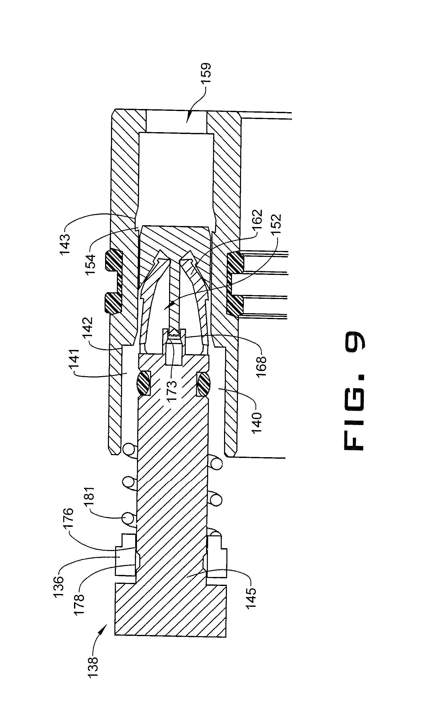
[0014] FIG. 9 depicts the AV of FIG. 8 showing the unitary piston member being ejected.
DETAILED DESCRIPTION
[0015] A detailed description of one or more embodiments of the disclosed apparatus and method are presented herein by way of exemplification and not limitation with reference to the Figures.
[0016] A resource recovery and exploration system, in accordance with an exemplary embodiment, is indicated generally at 2, in FIG. 1. Resource exploration and recovery system 2 should be understood to include well drilling operations, resource extraction and recovery, CO.sub.2 sequestration, and the like. Resource exploration and recovery system 2 may include a surface system 4 operatively connected to a downhole system 6. Surface system 4 may include pumps 8 that aid in completion and/or extraction processes as well as fluid storage 10. Fluid storage 10 may contain a drilling fluid or completion fluid (not shown) or other fluid which may be introduced into downhole system 6.
[0017] Downhole system 6 may include a downhole string 20 formed from a plurality of tubular components, one of which is indicated at 21 that is extended into a wellbore 24 formed in formation 26. Wellbore 24 includes an annular wall 28 that may be defined by a wellbore casing 29 provided in wellbore 24. Of course, it is to be understood, that annular wall 28 may also be defined by formation 26. Tubular 21 supports an inflow control device (ICD) 32 provided with an actuator valve (AV) 36.
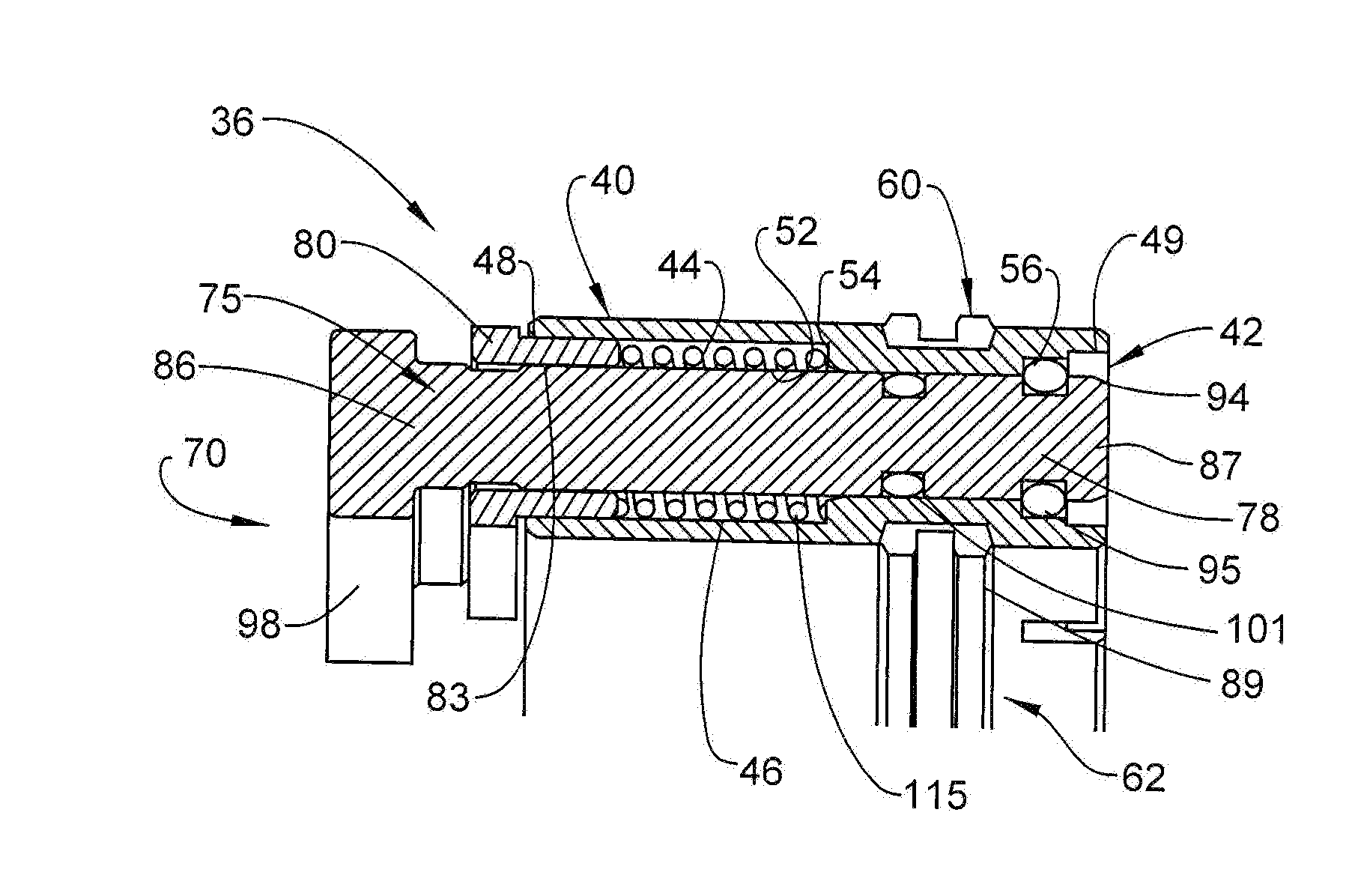
[0018] Referring to FIG. 2, AV 36 includes a valve body 40 having a piston member receiver 42 including an inner wall 44 defining a passage 46. Passage 46 includes a first end 48 that may be an inlet and a second end 49 that may be an outlet. Inner wall 44 includes an annular recess 53 defining a first annular shoulder 54 and a second annular recess (not separately labeled) defining a second annular shoulder 56. Valve body 40 is also shown to include an outer seal 60 and an inner seal 62. A unitary piston member 70 is arranged in piston member receiver 42.
[0019] Referring to FIG. 3, unitary piston member 70 include a unitary body 75 having a first portion (not separately labeled) defining a piston portion 78 and a second portion (also not separately labeled) defining a piston ring member 80. Piston portion 78 and piston ring member 80 are connected through one or more shear tabs 83. Shear tabs 83 create a gap 84 between piston portion and piston ring member 80. Shear tabs 83, when severed, allow piston portion 78 and piston ring member 80 to be ejected from piston member receiver 42. At this point, it should be understood that the term "unitary" describes that piston member 80 is formed as one component without the use of joints or the like that unite components. Unitary piston member could, for example, be formed through an additive manufacturing process.
[0020] In accordance with an aspect of an exemplary embodiment, piston portion 78 includes a first end section, a second end section, and an intermediate portion. A first ball receiving recess 91 and a second ball receiving recess 92 may be formed at second end 87. Each ball receiving recess 91, 92, is receptive to a corresponding first ball bearing 94 and a second ball bearing 95. First and second ball bearings 94 and 95 engage with second annular shoulder 56 to retain unitary piston member 70 within piston member receiver 42. First end section may support an activation member 98 that is selectively exposed to fluid pressure. Piston portion 78 may also include an annular recess 100 that is receptive of an O-ring 101 (FIG. 2). Annular recess 100 may be manufactures with piston member 70 or formed later through, for example, a machining process.
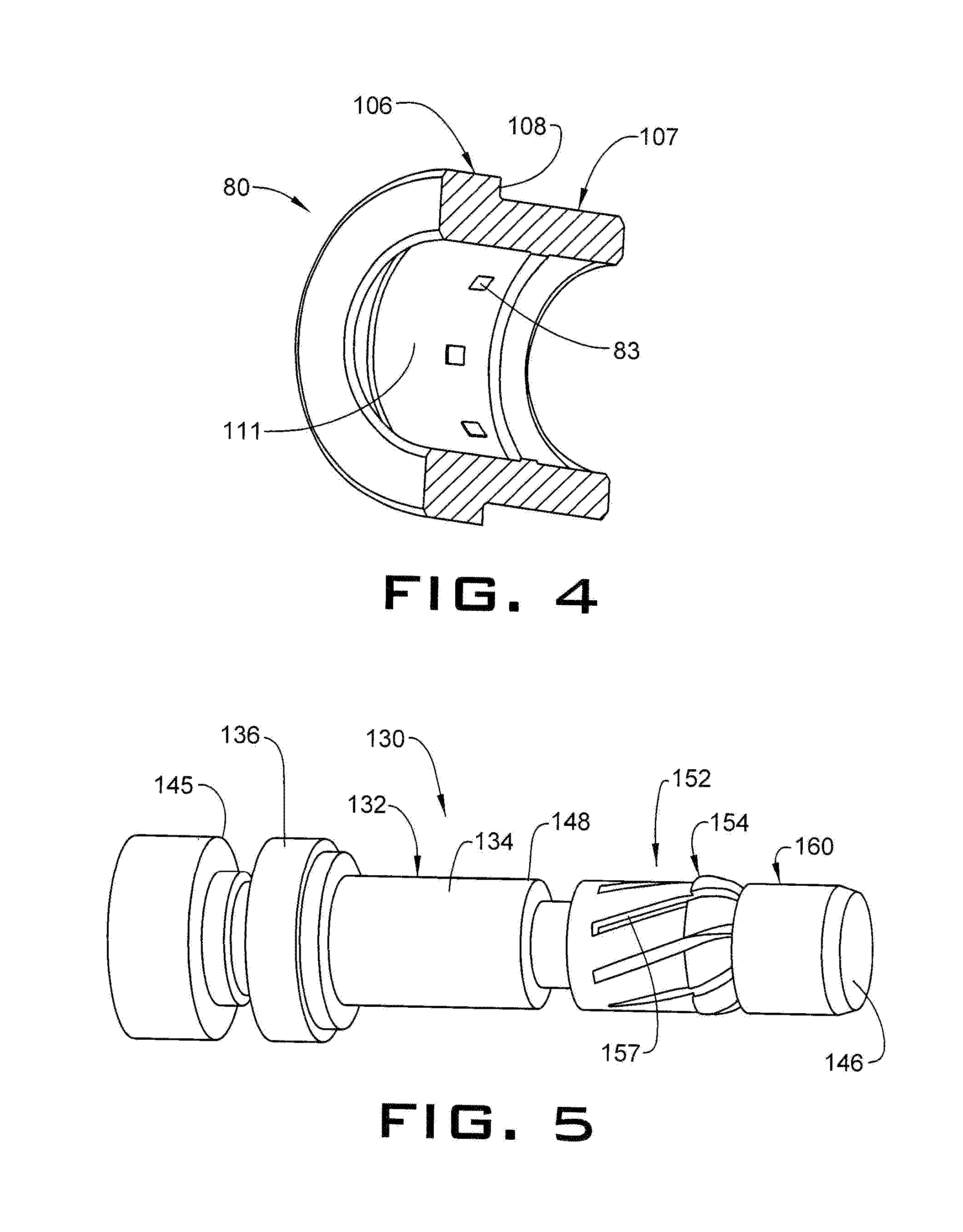
[0021] Reference will follow to FIG. 4 with continued reference to FIGS. 2 and 3 in describing piston ring member 80 in accordance with an exemplary aspect. Piston ring member 80 includes a first section 106 having a first diameter and a second section 107 having a second diameter that is greater than the first diameter. A step section 108 is disposed between first section 106 and second section 107. First section 106 is sized so as to be received in first end 48 of passage 46. Piston ring member 80 also includes an inner surface 111 from which extend shear tabs 83. As shown in FIG. 2, a spring 115 is arranged in first annular recess 52 between first annular shoulder 54 and piston ring member 80.
[0022] In operation, fluid pressure may be applied to activation member 98 causing piston portion 78 to shift into piston member receiver 42. The shifting of piston portion 78 causes shear tabs 83 to break. Piston portion 78 then axially translates relative to piston ring member 80. As piston portion 78 shift, first and second ball bearings 94 and 95 may disengage from second annular shoulder 56 and be released from corresponding ones of first and second ball bearing receiving recesses 91 and 92. First and second ball bearings 94 and 95 may then be captured by a magnet (not shown) in valve body 40. Fluid pressure may be removed so that spring 115 may eject unitary piston member 70 from piston member receiver 42. At this point, a fluid flow may pass through piston member receiver 42. The fluid flow may be employed to activate aspects of ICD 32.
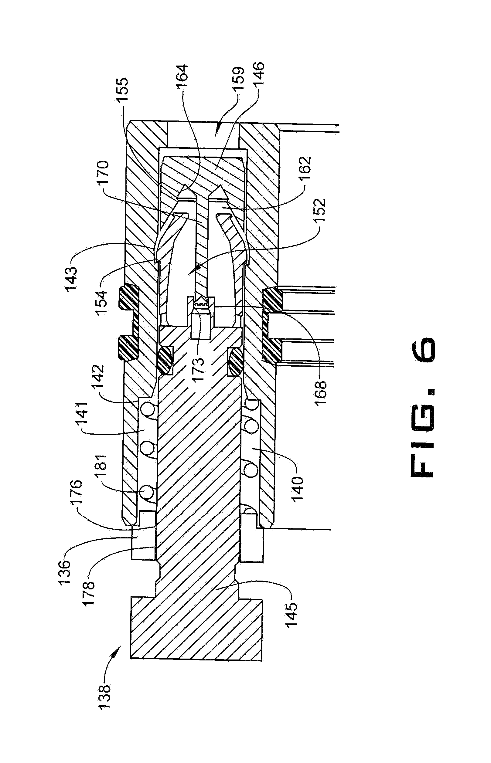
[0023] Reference will now follow to FIG. 5 in describing a unitary piston member 130 in accordance with another aspect of an exemplary embodiment. Unitary piston member 130 includes a unitary body 132 having a piston portion 134, and a piston ring member 136. Unitary piston member 130 is received by a piston member receiver 139 formed in an AV 138 shown in FIG. 6. Piston member receiver 139 include a passage 140 having a first annular recess 141 having an annular shoulder 142 and a second annular recess 143.
[0024] Piston portion 134 includes a first end section 145, a second end section 146 and an intermediate portion 148 extending therebetween. Piston portion 34 includes a plurality of cantilevered fingers 152 arranged between intermediate portion 148 and second end 146. Each of the plurality of cantilevered fingers 152 includes a first radially outwardly directed projection 154 and a second radially outwardly directed projection 155. First radially outwardly directed projection 154 is configured to interact with second annular recess 143 to retain unitary piston member 130 within piston member receiver 139. Cantilevered fingers 152 are defined by a plurality of slots 157 that spiral about piston portion 134. It should be understood that while slots 157 are shown spiraling about piston portion 134, the slots could also take on other forms. Further, cantilevered fingers 152 may take on other geometries including non-cantilevered arrangements.
[0025] Piston portion 134 also includes a stopper 160 that limits axial travel within piston member receiver 139. Stopper 160 includes a central bore 162 having an annular shoulder 164 which, as will be discussed herein, selectively cooperates with second radially outwardly directed projection 155. Stopper 160 is connected to a hub 168 formed centrally relative to cantilevered fingers 152. A support 170 extends from hub 168 into central bore 162. Support 170 is connected to hub 168 through one or more shear elements 173. Stopper 160, support 170, and shear elements 173 are all part of unitary piston member 130. Piston portion 134 is connected to piston ring member 136 through a plurality of shear tabs 176. Shear Labs 176 establish a gap 178 between piston portion 134 and piston ring member 136. A spring 181 is arranged in first annular recess 141 between shoulder 142 and piston ring member 136.
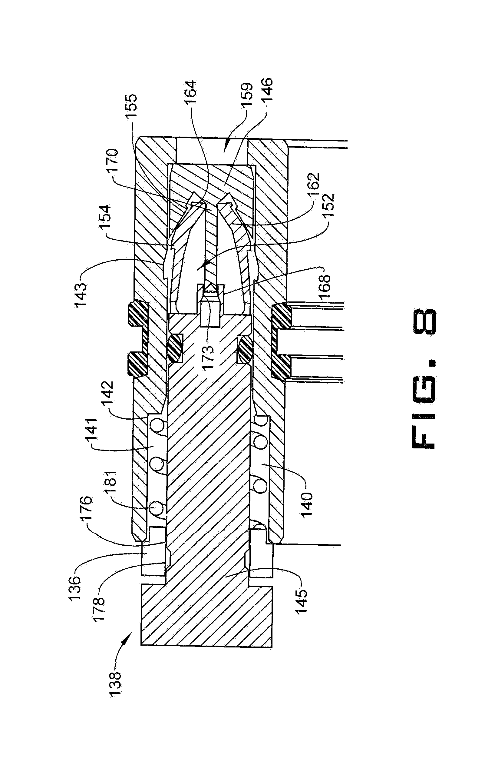
[0026] Reference will follow to FIGS. 7-9, with continued reference to FIGS. 5 and 6 in describing a method of operation of AV 138. Fluid pressure is applied to piston portion 134 at first end section 145. The fluid pressure causes piston portion 134 to shift within piston member receiver 139 relative to piston ring member 136. The shifting of piston portion 134 causes shear tab(s) 178 to shear forcing stopper 160 to bottom out in piston member receiver 139. Once stopper 160 bottoms out, further shifting of piston portion 134 causes shear element(s) 173 to shear allowing cantilevered fingers 152 to deflect and second radially outwardly directed projections 155 to be captured by annular shoulder 164 in central bore 162. Fluid pressure may be alleviated such that spring 181 ejects unitary piston member 130 from AV 138. At this point, fluid may flow through passage 140 to actuate elements within ICD 32.
[0027] Set forth below are some embodiments of the foregoing disclosure:
[0028] Embodiment 1: A member including a unitary body defining a first portion integrally joined with a second portion through one or more shear tabs.
[0029] Embodiment 2: The member according to any prior embodiment wherein the first portion defines a piston portion having a first end section including an activation member, a second end section, and an intermediate portion extending therebetween.
[0030] Embodiment 3: The member according to any prior embodiment, wherein the second portion defines a piston ring member disposed adjacent the first end section and includes a first section having a first diameter and a second section having a second diameter that is greater than the first diameter.
[0031] Embodiment 4: The member according to any prior embodiment, wherein the second end section includes at least one ball receiving recess and a ball arranged in the ball receiving recess.
[0032] Embodiment 5: The member according to any prior embodiment, wherein the second end section includes a plurality of cantilevered fingers, each of the plurality of cantilevered fingers including a first radially outwardly directed projection and a second radially outwardly directed projection axially spaced from the first radially outwardly directed projection.
[0033] Embodiment 6: The member according to any prior embodiment, wherein the second end section includes a hub including a recess and a stopper integrally joined to the hub through at least one shear element, the stopper limiting axial movement of the piston member.
[0034] Embodiment 7: The member according to any prior embodiment, where the stopper includes a central bore including an annular shoulder portion selectively receivable of the second radially outwardly directed projection.
[0035] Embodiment 8: The member according to any prior embodiment, wherein the second end section includes a plurality of slots defining the plurality of cantilevered fingers.
[0036] Embodiment 9: The member according to any prior embodiment, wherein each of the plurality of slots defines a spiral slot.
[0037] Embodiment 10: An actuator valve (AV) including a piston member receiver including an inner wall defining a passage, the inner wall including at least one annular shoulder, and a piston member including a unitary body defining a first portion integrally joined with a second portion through one or more shear tabs.
[0038] Embodiment 11: The AV according to any prior embodiment, wherein the first portion defines a piston portion of the unitary body including a first end section disposed axially outwardly of the passage, a second end section arranged within the passage and an intermediate portion extending therebetween.
[0039] Embodiment 12: The AV according to any prior embodiment, wherein the second portion defines a piston ring member disposed adjacent the first end section and includes a first section having a first diameter received by the passage and a second section having a second diameter that is greater than the first diameter.
[0040] Embodiment 13: The AV according to any prior embodiment, wherein the second end section includes at least one ball receiving recess and a ball arranged in the ball receiving recess, the ball being selectively engageable with the at least one annular shoulder preventing axially outwardly directed movement of the piston member relative to the passage.
[0041] Embodiment 14: The AV according to any prior embodiment, wherein the second end section includes a plurality of cantilevered fingers, each of the plurality of cantilevered fingers including a first radially outwardly directed projection and a second radially outwardly directed projection axially spaced from the first radially outwardly directed projection, the first radially outwardly directed projection being selectively engageable with the annular shoulder.
[0042] Embodiment 15: The AV according to any prior embodiment, wherein the second end section includes a hub including a recess and a stopper integrally joined to the hub through at least one shear element, the stopper limiting axial movement of the piston member into the passage.
[0043] Embodiment 16: The AV according to any prior embodiment, where the stopper includes a central bore including an annular shoulder portion selectively receivable of the second radially outwardly directed projection.
[0044] Embodiment 17: The AV according to any prior embodiment, wherein the second end section includes a plurality of slots defining the plurality of cantilevered fingers.
[0045] Embodiment 18: The AV according to any prior embodiment, wherein each of the plurality of slots defines a spiral slot.
[0046] Embodiment 19: The AV according to any prior embodiment, wherein the piston member receiver includes an annular recess having a shoulder portion and a spring arranged in the annular recess between the shoulder portion and the piston ring member.
[0047] Embodiment 20: The AV according to any prior embodiment, wherein the piston member receiver includes a fluid outlet selectively exposed to a fluid flow.
[0048] The use of the terms "a" and "an" and "the" and similar referents in the context of describing the invention (especially in the context of the following claims) are to be construed to cover both the singular and the plural, unless otherwise indicated herein or clearly contradicted by context. Further, it should further be noted that the terms "first," "second," and the like herein do not denote any order, quantity, or importance, but rather are used to distinguish one element from another. The modifier "about" used in connection with a quantity is inclusive of the stated value and has the meaning dictated by the context (e.g., it includes the degree of error associated with measurement of the particular quantity).
[0049] The teachings of the present disclosure may be used in a variety of well operations. These operations may involve using one or more treatment agents to treat a formation, the fluids resident in a formation, a wellbore, and/or equipment in the wellbore, such as production tubing. The treatment agents may be in the form of liquids, gases, solids, semi-solids, and mixtures thereof. Illustrative treatment agents include, but are not limited to, fracturing fluids, acids, steam, water, brine, anti-corrosion agents, cement, permeability modifiers, drilling muds, emulsifiers, demulsifiers, tracers, flow improvers etc. Illustrative well operations include, but are not limited to, hydraulic fracturing, stimulation, tracer injection, cleaning, acidizing, steam injection, water flooding, cementing, etc.
[0050] While the invention has been described with reference to an exemplary embodiment or embodiments, it will be understood by those skilled in the art that various changes may be made and equivalents may be substituted for elements thereof without departing from the scope of the invention. In addition, many modifications may be made to adapt a particular situation or material to the teachings of the invention without departing from the essential scope thereof. Therefore, it is intended that the invention not be limited to the particular embodiment disclosed as the best mode contemplated for carrying out this invention, but that the invention will include all embodiments falling within the scope of the claims. Also, in the drawings and the description, there have been disclosed exemplary embodiments of the invention and, although specific terms may have been employed, they are unless otherwise stated used in a generic and descriptive sense only and not for purposes of limitation, the scope of the invention therefore not being so limited.
* * * * *
D00000
D00001
D00002
D00003
D00004
D00005
D00006
D00007
XML
uspto.report is an independent third-party trademark research tool that is not affiliated, endorsed, or sponsored by the United States Patent and Trademark Office (USPTO) or any other governmental organization. The information provided by uspto.report is based on publicly available data at the time of writing and is intended for informational purposes only.
While we strive to provide accurate and up-to-date information, we do not guarantee the accuracy, completeness, reliability, or suitability of the information displayed on this site. The use of this site is at your own risk. Any reliance you place on such information is therefore strictly at your own risk.
All official trademark data, including owner information, should be verified by visiting the official USPTO website at www.uspto.gov. This site is not intended to replace professional legal advice and should not be used as a substitute for consulting with a legal professional who is knowledgeable about trademark law.