Method And Device For Producing Hardened Steel Components
HASLMAYR; JOHANNES ; et al.
U.S. patent application number 16/076923 was filed with the patent office on 2019-02-14 for method and device for producing hardened steel components. The applicant listed for this patent is voestalpine Metal Forming GmbH, voestalpine Stahl GmbH. Invention is credited to JOHANNES HASLMAYR, SIEGFRIED KOLNBERGER, HARALD SCHWINGHAMMER, ANDREAS SOMMER, BENEDIKT TUTEWOHL.
| Application Number | 20190048432 16/076923 |
| Document ID | / |
| Family ID | 58185488 |
| Filed Date | 2019-02-14 |

| United States Patent Application | 20190048432 |
| Kind Code | A1 |
| HASLMAYR; JOHANNES ; et al. | February 14, 2019 |
METHOD AND DEVICE FOR PRODUCING HARDENED STEEL COMPONENTS
Abstract
The invention relates to a method for press hardening sheet steel components in which a blank is detached from a sheet steel band composed of a hardenable steel alloy and the blank is then austenitized, in that it is heated to a temperature greater than Ac.sub.3 and is then inserted into a forming tool and formed in the forming tool, and during the forming, is cooled at a speed greater than the critical hardening speed, characterized in that in order to inhibit microcracks of the second type from being produced during the forming and hardening process in the sheet metal blanks that are to be formed, oxygen is supplied adjacent to the positive radii and/or drawing edges; the invention also relates to a device for performing this method.
| Inventors: | HASLMAYR; JOHANNES; (Linz, AT) ; KOLNBERGER; SIEGFRIED; (Pasching, AT) ; SCHWINGHAMMER; HARALD; (Pasching, AT) ; SOMMER; ANDREAS; (Abtsgmund, DE) ; TUTEWOHL; BENEDIKT; (Durlangen, DE) | ||||||||||
| Applicant: |
|
||||||||||
|---|---|---|---|---|---|---|---|---|---|---|---|
| Family ID: | 58185488 | ||||||||||
| Appl. No.: | 16/076923 | ||||||||||
| Filed: | February 7, 2017 | ||||||||||
| PCT Filed: | February 7, 2017 | ||||||||||
| PCT NO: | PCT/EP2017/052603 | ||||||||||
| 371 Date: | August 9, 2018 |
| Current U.S. Class: | 1/1 |
| Current CPC Class: | C21D 1/673 20130101; C21D 9/48 20130101 |
| International Class: | C21D 1/673 20060101 C21D001/673 |
Foreign Application Data
| Date | Code | Application Number |
|---|---|---|
| Feb 10, 2016 | DE | 102016102322.1 |
Claims
1. A method for press hardening sheet steel components in which a blank is detached from a sheet steel band composed of a hardenable steel alloy and the blank is then austenitized, the method comprising: heating the blank to a temperature greater than Ac.sub.3; inserting the blank into a forming tool having a mold cavity; and forming the blank in the forming tool, wherein during the forming, the blank is cooled at a speed greater than the critical hardening speed, characterized in that in order to avoid microcracks of second type from forming in the sheet metal blanks to be formed during the forming and a subsequent hardening, an oxygen-containing fluid reservoir is present adjacent to positive radii and/or drawing edge and/or in other contact regions outside of the positive radii and/or drawing edges.
2. The method according to claim 1, characterized in that entry of oxygen takes place by means of at least one recess provided in the forming tool adjacent to the drawing edges and/or positive radii, which are dimensioned so that deep drawing is not negatively affected and the recess forms a reservoir for oxygen-containing fluids or else oxygen-containing fluids can be supplied via this recess.
3. The method according to claim 2, characterized in that the entry of oxygen-containing fluid is ensured by means of the air that is present in the recess.
4. The method according to claim 2, characterized in that the recess is supplied with fluids or oxygen or oxygen-containing fluids from the forming tool side, or the recess or mold cavity is supplied with fluids, in particular oxygen or an oxygen-containing fluid, between two forming procedures.
5. The method according to claim 2, characterized in that vacuum is applied to the recess.
6. The method according to claim 1, characterized in that oxygen-containing fluid is supplied continuously.
7. A device for performing the method according to claim 1, having two faulting tool halves; the two forming tool halves cooperate in order to deep-draw a blank and are embodied so that they can move toward and away from each other; depending on a desired forming contour, at least one positive radius (1) or one drawing edge region (1) is provided with a drawing edge (2), wherein a recess (5) is provided in a surface (4) that is situated after the drawing edge (2) or the positive radius (1) in the drawing direction and/or in other contact regions outside of the positive radii (1) and/or drawing edge (2).
8. The device according to claim 7, characterized in that the recess (5) is dimensioned so that the remaining thickness of the drawing edge (2) between a surface, which adjoins the drawing edge (2), and the recess (5) corresponds approximately to its radius.
9. The device according to claim 7, characterized in that the recess (5) between the drawing edge (2) and a forming tool surface (4) has a height, which corresponds to approximately 25 to 35 mm at a depth of 5 to 9 mm or is embodied as a groove (6), which has a height between the surface (4) and the drawing edge (2), which totals approximately 8 to 12 mm, with a depth of 5 to 9 mm or in the region of the wall (4) adjacent to the drawing edge (2), a plurality of recesses in the form of grooves (7) extending in the drawing direction; and the grooves (7) or slots (7) have a slot width of 4 to 8 mm and a slot spacing of 7 to 11 mm so that remaining bridge pieces have a width of 1 to 5 mm.
10. The device according to claim 9, characterized in that the recesses (5), the grooves (6), or the slot (7) are supplied from the rear, i.e. from the tool side, with an oxygen-containing fluid by means of supply openings and correspondingly drilled lines.
Description
[0001] The invention relates to a method and device for producing hardened steel components.
[0002] Hardened steel components, particularly in vehicle body construction for motor vehicles, have the advantage that due to their outstanding mechanical properties, it is possible to achieve a particularly stable passenger compartment without having to use components that are much more massive at normal strengths and must therefore be embodied as much heavier.
[0003] To produce hardened steel components of this kind, steel types are used that can be hardened by means of a quench hardening. Steel types of this kind include, for example, boron-alloyed manganese carbon steels, the most widely-used of these being 22MnB5. But other boron-alloyed manganese carbon steels are also used for this purpose.
[0004] In order to produce hardened components from these types of steel, the steel material must be heated to the austenitization temperature (>Ac.sub.3) and it is necessary to wait until the steel material is austenitized. Depending on the desired degree of hardness, partial or complete austenitization can be achieved in this connection.
[0005] If after the austenitization, such a steel material is cooled at a speed that is above the critical hardening speed, then the austenitic structure converts into a martensitic, very hard structure. In this way, it is possible to achieve tensile strengths R.sub.in of up to over 1500 MPa.
[0006] Currently, two different procedural approaches are commonly used for producing steel components.
[0007] In so-called form hardening, a sheet steel blank is detached from a steel band, for example cut out or stamped out from it, and then--using a conventional, for example five-step, deep drawing process--is deep drawn to produce the finished component. This finished component in this case is dimensioned somewhat smaller in order to compensate for a subsequent thermal expansion during the austenitization.
[0008] The component produced in this way is austenitized and then inserted into a form hardening tool in which it is pressed, but is not formed or is only formed to a very slight extent and by means of the pressing, the heat flows out of the component and into the press tool, specifically at the speed greater than the critical hardening speed.
[0009] The other procedural approach is so-called press hardening in which a blank is detached from a sheet steel band, for example cut out or stamped out from it, then the blank is austenitized and the hot blank is formed at a temperature below 782.degree. C. in a preferably one-stage step and at the same time, is cooled at a speed greater than the critical hardening speed.
[0010] In both cases, it is possible to use blanks provided with metallic anticorrosion coatings e.g. with zinc or a zinc-based alloy. Form hardening is also referred to as the indirect process and press hardening is referred to as the direct process. The advantage of the indirect process is that it is possible to achieve more complex tool geometries.
[0011] The advantage of the direct method is that a higher material utilization ratio can be achieved. But the achievable component complexity is lower, especially with the one-stage forming process.
[0012] In press hardening, however, it is disadvantageous that microcracks form in the surface, particularly with galvanized sheet steel blanks.
[0013] In this connection, a distinction is drawn between first-order microcracks and second-order microcracks.
[0014] First-order microcracks are attributed to so-called liquid metal embrittlement. The theory is that during the forming, i.e. as tensile stresses are being exerted on the material, liquid zinc phases interact with still existing austenite phases, causing microcracks with depths of up to a few hundred .mu.m to be produced in the material.
[0015] The applicant has succeeded in suppressing these first-order microcracks by actively or passively cooling the material--in the time between the removal from the heating furnace and the start of the hot-forming process--to temperatures at which liquid zinc phases are no longer present. This means that the hot-forming takes place at temperatures below approximately 750.degree. C.
[0016] Up to this point, it has not been possible to control the second-order microcracks in hot-forming despite pre-cooling and they occur even at hot-forming temperatures below 600.degree. C. The crack depths in this case amount to a few tens of .mu.m.
[0017] Neither first-order microcracks nor second-order microcracks are accepted by users since they constitute potential sources of damage.
[0018] With the previous methods, it has not yet been possible to ensure a production of components without second-order microcracks.
[0019] DE 10 2011 055 643 A1 has disclosed a method and a forming tool for hot-form press hardening components made of sheet steel, particularly made of galvanized workpieces composed of sheet steel. In this case, the female dies used for the hot-forming and press hardening--in their drawing edge region that is defined by a positive drawing radius--should be liquid-coated with a material or provided with an insert piece, which has a thermal conductivity that is at least 10 W/(m.times.K) less than the thermal conductivity of the section of the female die that is adjacent to the drawing edge region and that comes into contact with the workpiece as the latter is being hot-formed and press hardened. The material that is applied to the surface of the drawing edge region facing the workpiece or of the insert piece that has been put into position should have a transverse dimension extending across the drawing edge that is in a range of 1.6 to 10 times the positive drawing radius of the female die. This should improve the flow properties of workpieces made of sheet steel during the hot-forming and should thus significantly reduce the risk of the occurrence of cracks in the hot-forming of workpieces made of sheet steel, preferably made of galvanized steel blanks. Such a tool, however, does not make it possible to avoid microcracks of the second type.
[0020] DE 10 2011 052 773 A1 has disclosed a tool for a press hardening tool in which the mold surface of the tool is microstructured in some regions by two micro-cavities that are introduced into the mold surface. This step is intended to four restrict the effective contact area for the forming of a blank between the mold surface with a blank to the surface portions situated between the cavities. This is intended to reduce the friction.
[0021] DE 10 2004 038 626 B3 has disclosed a method for producing hardened components out of sheet steel in which before or after the forming of the formed part, a required final trimming of the formed part and any necessary punching procedures or the production of a hole pattern is carried out and the formed part is then heated at least in some areas to a temperature that enables an austenitization of the steel material; the component is then transferred to a form hardening tool and a form hardening is carried out in the form hardening tool in which the component is cooled and thus hardened at least in some areas by the contact and pressing of the component; and the component is supported by the form hardening tool in the region of the positive radii and is preferably held by two clamps in the region of the trim edges and in regions in which the component is not clamped, the component is at least spaced apart from a mold half by means of a gap. This measure makes it possible to clamp the component in a distortion-free manner and to set different hardness gradients by means of different hardening speeds.
[0022] The object of the invention is to avoid microcracks of the second type in directly hot-formed, i.e. press hardened, components.
[0023] The object attained with a method having the features of claim 1.
[0024] Advantageous modifications are characterized in the dependent claims.
[0025] Another object of the invention is to create a device with which sheet steel blanks can be hot-formed and hardened in the press hardening process and in which microcracks are avoided.
[0026] The object is attained with a device having the features of claim 6. Advantageous modifications are characterized in the dependent claims that depend on this claim.
[0027] The inventors have realized that microcracks of the second type are produced when, in regions under tensile strain, the zinc vapor that occurs arrives at the steel in a sufficient concentration, so-called vapor metal embrittlement (VME). Zinc vapor is produced due to the tearing of the zinc/iron layer that occurs in the stretching during the forming process. A sufficient concentration particularly occurs in those regions in which direct contact of the sheet metal with the tool prevails or the sheet metal is a very small distance from the tool. A very small distance as defined by the invention is being less than 0.5 mm.
[0028] According to the invention, second-order microcracks should be avoided, while retaining the largest possible working window with regard to the material and temperature and ensuring an inexpensive implementation. With at least the same residence time, there should be no increase in cycle time or reduction in throughput during component production.
[0029] According to the invention, in the regions under tensile strain (elongation edge fiber), the zinc vapor that occurs is either conveyed away by gas flows (convection) or more precisely, blown away, or is sufficiently diluted. Alternatively or in addition to this, through an influx of fluids, zinc can be quickly transformed into a stable compound such as zinc oxide or ZnI.sub.2. In addition, the protection of the steel from second-order microcracks can also be achieved by producing a protective layer such as an oxide layer by supplying a fluid. All of the measures described above have respectively demonstrated that microcracks are significantly reduced.
[0030] Gaseous oxygen-containing fluids such as air or oxygen are particularly preferable because they cannot excessively contaminate the tool and in addition, a possibly unwanted massive cooling action of the kind that can occur, for example, by means of water can be more easily regulated by tempering the fluid.
[0031] In this case, the avoidance of second-order microcracks is ensured by the fact that in the region of the positive radii, i.e. in the drawing edge region of the female die and/or male die, after the drawing edge or other contact regions situated outside of the positive radii/drawing edge in the drawing direction, a recess is provided, which is dimensioned so that on the one hand, the deep drawing is not negatively affected or the blank or workpiece becomes wavy and on the other hand, is dimensioned so that the outflow of heat that is necessary for the hardening is likewise not negatively affected to a significant degree.
[0032] The recesses, however, are dimensioned so that they constitute a reservoir for oxygen in such a way that a sufficient amount of oxygen travels to the blank that is being drawn and to the material in order to supply oxygen for oxidation to the zinc phases or zinc/iron phases that are being released.
[0033] The recess functions as a fluid reservoir in particular for oxygen, but this reservoir can also contain other fluids such as water or also nitrogen. If these reservoirs are filled with an inert gas or are also continuously flushed with an inert gas, then they do not function by means of oxidation, but rather by diluting or carrying away the zinc vapor that occurs.
[0034] If need be, the recesses can advantageously be continuously supplied from the tool side with oxygen-containing fluids during the forming, for example via suitable entry openings, advantageously permitting a flow cushion to form. In addition, after the removal of a workpiece from the mold and before the insertion of another blank, the mold cavity can be flushed with a fluid, in particular oxygen-containing one, which is then present in the recesses. Examples of an oxygen-containing fluid include air as well as water, i.e. they can be supplied in both liquid and gaseous form.
[0035] It has turned out that these recesses, even when their dimensions are only relatively small, effectively prevent the formation of second-order microcracks through oxidation of zinc phases or zinc/iron phases.
[0036] The invention will be explained by way of example based on the drawings. In the drawings:
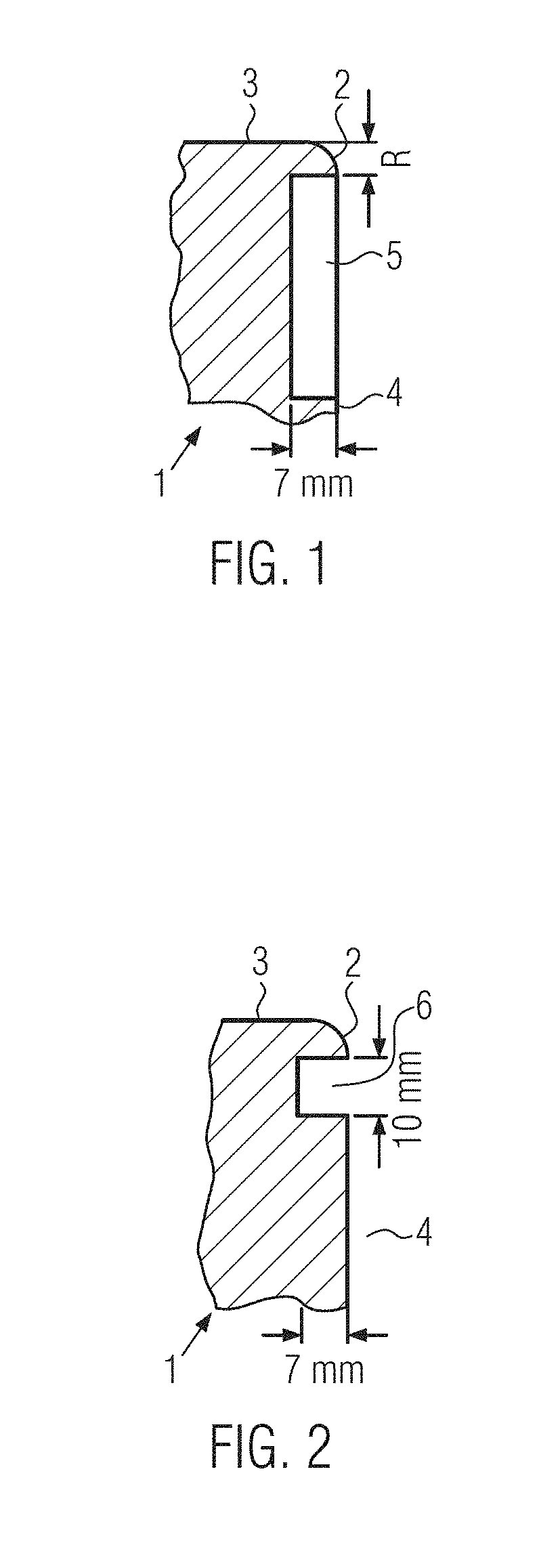
[0037] FIG. 1 shows the tool region adjacent to a drawing edge with a recess according to the invention;
[0038] FIG. 2 shows the drawing edge region of a tool with a different embodiment of the recess according to the invention;
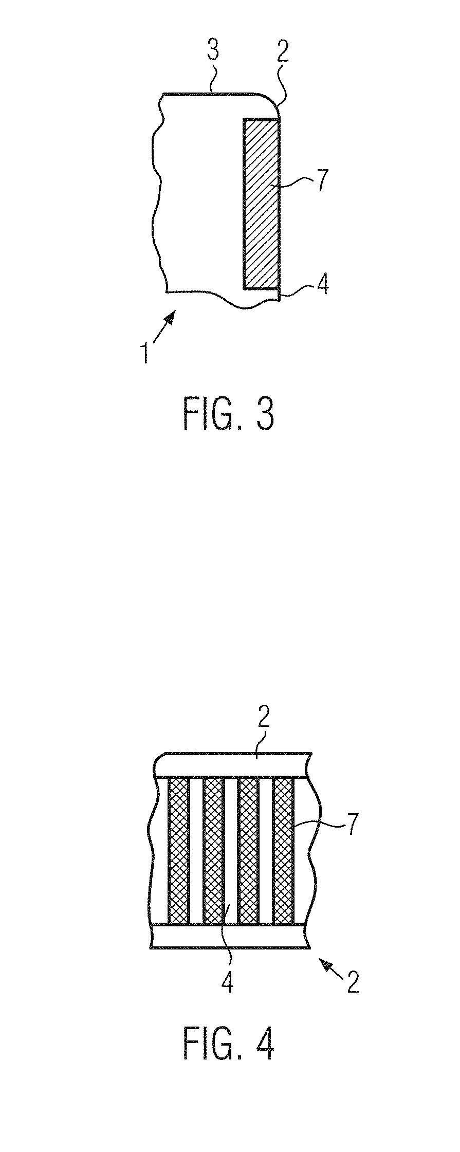
[0039] FIG. 3 is a partially cut-away side view of the drawing edge region of a tool with a slot arrangement according to the invention;
[0040] FIG. 4 is a top view of the arrangement according to FIG. 3.
[0041] The drawing edge region 1 or the region of a positive radius 1 is positioned on a forming tool and has two surfaces 3, 4 oriented toward the workpiece, which meet in the region of a drawing edge or positive radius 2.
[0042] A recess 5 according to the invention is provided in a surface 4 situated after the drawing edge 2 in the drawing direction. The recess 5 in this case is dimensioned so that the remaining thickness of the drawing edge 2 between the surface 3 and the recess 5 corresponds approximately to its radius in order to offer a sufficient supporting action for the material that is to be drawn.
[0043] Naturally, other recesses can be provided, which are positioned in regions in which the sheet metal contacts the tool; these contact regions are defined by means of a maximum distance of approx. 0.5 mm between the sheet metal and the tool.
[0044] Between the drawing edge 2 and the surface 4, the recess 5 has a height that is approximately 25 to 35 mm, with a depth of 5 to 9 mm.
[0045] In another advantageous embodiment (FIG. 2), instead of providing a large-area recess 5 adjacent to the drawing edge 2 and leaving it with the thickness described above, a groove 6 is introduced into the surface 4. The groove 6 in this case has a height between the surface 4 and the drawing edge 2 that totals approximately 8 to 12 mm, with a depth of 5 to 9 mm.
[0046] In a further embodiment, instead of a continuous recess 5 in the region of the wall 4 adjacent to the drawing edge 2, a plurality of grooves 7 is provided, which extend in the drawing direction; for example, the grooves 7 or slots 7 have a slot width of 4 to 8 mm and a slot spacing of 7 to 11 mm so that the remaining bridge pieces have a width of 1 to 5 mm. The grooves 7 or slots 7 in this case likewise have a depth of 5 to 9 mm.
[0047] It has surprisingly turned out that with the above-mentioned geometries, the relatively small quantity of fluid inside the recesses 5, 6, 7--possibly even despite the presence of the bridge pieces 4--is sufficient in order to effectively prevent the formation of microcracks of the second type through the provision of oxygen.
[0048] In an advantageous embodiment (not shown), the recesses 5, the groove 6, and the slots 7 are supplied from the rear, i.e. from the tool side, with an oxygen-containing fluid by means of supply openings and correspondingly drilled lines in order, if need be, to further increase the partial pressure of oxygen in the region of the recesses 5, grooves 6, and slots 7.
[0049] In order to keep the oxygen content at a high level in the recesses 5, grooves 6, and slots 7 during continuous processing, the mold cavity can also be flushed with an oxygen-containing fluid so that at all times, there is a sufficient oxygen reservoir in the recesses 5, grooves 6, and slots 7.
[0050] Primarily in the direct press hardening process, 20MnB8, 22MnB8, and other manganese/boron steels are also used in addition to 22MnB5.
[0051] Consequently, steels of the following alloy composition are suitable for the invention (all indications in mass %):
TABLE-US-00001 C Si Mn P S Al Cr Ti B N [%] [%] [%] [%] [%] [%] [%] [%] [%] [%] 0.20 0.18 2.01 0.0062 0.001 0.054 0.03 0.032 0.0030 0.0041
and the rest made up of iron and smelting-induced impurities; in such steels, particularly the alloy elements boron, manganese, carbon, and optionally chromium and molybdenum, are used as transformation-delaying agents.
[0052] Steels of the following general alloy composition are also suitable for the invention (all indications in mass %):
TABLE-US-00002 Carbon (C) 0.08-0.6 Manganese (Mn) 0.8-3.0 Aluminum (Al) 0.01-0.07 Silicon (Si) 0.01-0.8 Chromium (Cr) 0.02-0.6 Titanium (Ti) 0.01-0.08 Nitrogen (N) <0.02 Boron (B) 0.002-0.02 Phosphorus (P) <0.01 Sulfur (S) <0.01 Molybdenum (Mo) <1
and the rest made up of iron and smelting-induced impurities.
[0053] The following steel configurations have turned out to be particularly suitable (all indications in mass %).
TABLE-US-00003 Carbon (C) 0.08-0.35 Manganese (Mn) 1.00-3.00 Aluminum (Al) 0.03-0.06 Silicon (Si) 0.01-0.20 Chromium (Cr) 0.02-0.3 Titanium (Ti) 0.03-0.04 Nitrogen (N) <0.007 Boron (B) 0.002-0.006 Phosphorus (P) <0.01 Sulfur (S) <0.01 Molybdenum (Mo) <1
and the rest made up of iron and smelting-induced impurities.
* * * * *
D00000
D00001
D00002
XML
uspto.report is an independent third-party trademark research tool that is not affiliated, endorsed, or sponsored by the United States Patent and Trademark Office (USPTO) or any other governmental organization. The information provided by uspto.report is based on publicly available data at the time of writing and is intended for informational purposes only.
While we strive to provide accurate and up-to-date information, we do not guarantee the accuracy, completeness, reliability, or suitability of the information displayed on this site. The use of this site is at your own risk. Any reliance you place on such information is therefore strictly at your own risk.
All official trademark data, including owner information, should be verified by visiting the official USPTO website at www.uspto.gov. This site is not intended to replace professional legal advice and should not be used as a substitute for consulting with a legal professional who is knowledgeable about trademark law.