Method And Plant Design For Reduction Of Start-up Sulfur Oxide Emissions In Sulfuric Acid Production
GRANROTH; Marten Nils Rickard ; et al.
U.S. patent application number 15/765683 was filed with the patent office on 2019-02-14 for method and plant design for reduction of start-up sulfur oxide emissions in sulfuric acid production. This patent application is currently assigned to HALDOR TOPSOE A/S. The applicant listed for this patent is HALDOR TOPSOE A/S. Invention is credited to Kurt Agerb.ae butted.k CHRISTENSEN, Marten Nils Rickard GRANROTH, Per Aggerholm SORENSEN.
| Application Number | 20190047859 15/765683 |
| Document ID | / |
| Family ID | 57184475 |
| Filed Date | 2019-02-14 |
| United States Patent Application | 20190047859 |
| Kind Code | A1 |
| GRANROTH; Marten Nils Rickard ; et al. | February 14, 2019 |
METHOD AND PLANT DESIGN FOR REDUCTION OF START-UP SULFUR OXIDE EMISSIONS IN SULFURIC ACID PRODUCTION
Abstract
The invention is a method and a sulfuric acid plant design for reduction of start-up SO.sub.2, SO.sub.3 and H.sub.2SO.sub.4 emissions in sulfuric acid production, in which SO2 is converted to SO.sub.3 in n successive catalyst beds, where n is an integer >1. The final catalytic beds are used as absorbents for SO.sub.2 to SO3 during the start-up procedure, and one or more of the m beds downstream the first bed are purged, either separately or simultaneously, with hot gas, where m is an integer >1 and m<n, during the previous shut-down. Also, one separate purge with hot gas is used on the final bed.
| Inventors: | GRANROTH; Marten Nils Rickard; (Bunkeflostrand, SE) ; SORENSEN; Per Aggerholm; (Kgs. Lyngby, DK) ; CHRISTENSEN; Kurt Agerb.ae butted.k; (Birkerod, DK) | ||||||||||
| Applicant: |
|
||||||||||
|---|---|---|---|---|---|---|---|---|---|---|---|
| Assignee: | HALDOR TOPSOE A/S Kgs. Lyngby DK |
||||||||||
| Family ID: | 57184475 | ||||||||||
| Appl. No.: | 15/765683 | ||||||||||
| Filed: | October 24, 2016 | ||||||||||
| PCT Filed: | October 24, 2016 | ||||||||||
| PCT NO: | PCT/EP2016/075492 | ||||||||||
| 371 Date: | April 3, 2018 |
| Current U.S. Class: | 1/1 |
| Current CPC Class: | B01D 2255/20723 20130101; B01D 53/1481 20130101; B01J 21/12 20130101; Y02A 50/2349 20180101; B01J 27/055 20130101; B01D 2257/302 20130101; C01B 17/7655 20130101; B01D 2255/202 20130101; B01J 23/22 20130101; C01B 17/79 20130101; Y02A 50/20 20180101; B01J 21/08 20130101; Y02A 50/2348 20180101; C01B 17/78 20130101; C01B 17/803 20130101 |
| International Class: | C01B 17/765 20060101 C01B017/765; C01B 17/79 20060101 C01B017/79; C01B 17/80 20060101 C01B017/80; B01J 27/055 20060101 B01J027/055; B01J 21/08 20060101 B01J021/08; B01J 21/12 20060101 B01J021/12; B01J 23/22 20060101 B01J023/22 |
Foreign Application Data
| Date | Code | Application Number |
|---|---|---|
| Nov 6, 2015 | DK | PA 2015 00697 |
Claims
1. A method for reduction of start-up SO.sub.2, SO.sub.3 and H.sub.2SO.sub.4 emissions in sulfuric acid production, in which SO.sub.2 is converted to SO.sub.3 in n successive catalyst beds, where n is an integer >1, wherein the final catalyst beds are used as absorbents for SO.sub.2 and SO.sub.3 during the start-up procedure, one or more of the m beds downstream the first bed are purged, either separately or simultaneously, with hot gas, where m is an integer >1 and m<n, during the previous shutdown, and one separate purge with hot gas is used on the final bed.
2. A method according to claim 1, wherein one separate purge with hot gas is used on the bed prior to the final bed, and wherein the gas from the purged bed is fed to the final bed.
3. A method according to claim 1, wherein two or more beds downstream the first bed are purged separately with hot gas.
4. A method according to claim 1, wherein two or more beds downstream the first bed are purged simultaneously with hot gas.
5. A method according to claim 1, where the catalyst comprises a vanadium(V) compound, sulfur in the form of sulfate, pyrosulfate, tri- or tetrasulfate and alkali metals, such as Li, Na, K, Rb or Cs, on a porous carrier.
6. A method according to claim 5, wherein the porous carrier of the catalyst is silicon dioxide (SiO.sub.2).
7. A method according to claim 6, wherein the porous carrier of the catalyst is SiO.sub.2 with less than 10 wt %, preferably less than 5 wt %, of alumina.
8. A method according to claim 7, wherein the porous carrier of the catalyst is SiO.sub.2 with less than 2 wt %, preferably less than 1 wt %, of alumina.
9. A method according to claim 8, wherein the alkali metal content of the catalyst is 2-25 wt %, preferably 4-20 wt % and most preferably 8-16 wt %.
10. A method according to claim 5, wherein the catalyst contains 1-15 wt % of a vanadium(V) compound such as V.sub.2O.sub.5.
11. A method according to claim 10, wherein the catalyst contains 2-12 wt %, preferably 4-10 wt % of a vanadium(V) compound such as V.sub.2O.sub.5.
12. A method according to claim 5, wherein the catalyst contains 1-25 wt % sulfur in the form of sulfate, pyrosulfate, tri- or tetrasulfate.
13. A method according to claim 12, wherein the catalyst contains 2-20 wt % sulfur, preferably 3-18 wt % sulfur, in the form of sulfate, pyrosulfate, tri- or tetrasulfate.
14. A method according to claim 13, wherein the catalyst contains 4-16 wt % sulfur, preferably 4-10 wt % sulfur, in the form of sulfate, pyrosulfate, tri- or tetrasulfate.
15. A method according to claim 1, wherein the hot gas is air fed to the final bed at a temperature of 0-650.degree. C., preferably 400-600.degree. C.
16. A sulfuric acid plant design provided with means for securing reduced start-up emissions of SO.sub.2, SO.sub.3 and H.sub.2SO.sub.4, said plant design comprising n successive catalyst beds, where n is an integer >1, wherein the final catalytic beds are used as absorbents for SO.sub.2 and SO.sub.3 during the start-up procedure, one or more of the m beds downstream the first bed are purged, either separately or simultaneously, with hot gas, where m is an integer >1 and m<n, during the previous shutdown, and one separate purge with hot gas is used on the final bed.
Description
[0001] The present invention relates to a method and a plant design for reduction of start-up emissions of sulfur oxides, i.e. SO.sub.2, SO.sub.3 and H.sub.2SO.sub.4, in sulfuric acid production.
[0002] Sulfuric acid plants can basically produce three types of harmful (and thus regulated) gas emissions: Sulfur dioxide (SO.sub.2), sulfur trioxide (SO.sub.3) and sulfuric acid (H.sub.2SO.sub.4). Both SO.sub.3 and H.sub.2SO.sub.4 are emitted as micron- or submicron-sized sulfuric acid mist because SO.sub.3 reacts rapidly with water vapor present in the ambient air or in the process gas to produce H.sub.2SO.sub.4. While essentially all sulfuric acid plants have emission limitations during continuous operation, the regulation requirements during start-up of the plant vary widely. These start-up emissions are gaining still more attention from both regulatory authorities and sulfuric acid producers.
[0003] During plant start-up, the catalyst in the catalytic sulfuric acid converter is in a transition state from colder temperatures towards regular optimum operating conditions. When SO.sub.2 is first passed over the catalyst, the SO.sub.2 emissions may increase to above 1000 ppm for several minutes until regular temperature profiles are established. Also during start-up, as the sulfuric acid in the absorption towers heats up to normal optimum operating temperatures, the SO.sub.3 absorption efficiency is lower, and a persistent acid plume may be seen from the plant stack until the acid temperature is sufficiently high.
[0004] Different strategies known in the art to reduce the SO.sub.2 and H.sub.2SO.sub.4 emissions during start-up include catalyst selection, catalyst purging and pre-heating, simultaneous pre-heating of catalyst beds, sulfuric acid pre-heating, acid aerosol removal and sulfur oxide scrubbing. These strategies are e.g. described or at least mentioned in WO 2012/068336 A1, WO 2005/105666 A1, U.S. Pat. No. 7,820,134 B2, WO 2009/065485 A1, US 2010/0015035 A1, DE 102 49 782, US 2008/0056971 A1, U.S. Pat. No. 5,344,614 B2 and WO 2015/058804 A1.
[0005] The increased attention on emissions during start-up of sulfuric acid plants calls for a better understanding of the dynamics of the plants and the phenomena, which control the emissions of SO.sub.2 and acid mist. Typically, sulfuric acid plants are designed by setting up steady-state heat and mass balances for the plant, and the equipment and catalyst volumes are sized based on steady-state models of individual unit operations. However, during start-up, shutdown and change of inlet feed, steady-state models may be inadequate for design and prediction of plant performance, and hence transient modelling is required.
[0006] In modern sulfuric acid plants, very low emissions of SO.sub.2 and H.sub.2SO.sub.4 can be achieved during stable operation if the plant is properly designed and maintained. The minimum SO.sub.2 emission is determined primarily by the catalytic sulfuric acid converter, and it is affected by the equilibrium of the SO.sub.2 oxidation reaction (1), bed inlet temperatures, gas distribution and amounts and activities of the catalysts in the converter beds.
SO.sub.2+1/2O.sub.2<->SO.sub.3+heat (1)
[0007] During start-up of a sulfuric acid converter, the catalytic beds are pre-heated with hot air before introduction of the SO.sub.2 feed gas. This pre-heating is necessary in order to "ignite" the SO.sub.2 oxidation catalyst before SO.sub.2 is introduced to the converter. The ignition temperature represents the lowest entering gas temperature for a specified adiabatic operating situation which will sustain a fairly close approach to equilibrium at the outlet. The industrially important vanadium pentoxide (V.sub.2O.sub.5) catalyst is a "supported liquid phase" (SLP) catalyst, where the active phase is a liquid salt mixture partly filling the pores of a porous support. At the ignition temperature, the salt mixture in the catalyst melts and dissolves part of the vanadium as active vanadium (V) compounds and also allows dissolution and diffusion of the gases (SO.sub.2, O.sub.2 and SO.sub.3) in the liquid. The ignition temperature is typically in the range of 320-380.degree. C. depending on the type of catalyst. As the temperature approaches the ignition temperature, SO.sub.3 trapped in the catalyst during shut-down may be released, pass through the heat exchangers and generate a bluish-white plume of sub-micron acid aerosols. After the pre-heating stage, SO.sub.2 gas is fed to the converter. Often the pre-heated catalysts will not be at their optimal operating temperatures, which may result in considerable SO.sub.2 emissions for a period of time because not all SO.sub.2 is converted to SO.sub.3. Initially, SO.sub.2 is therefore typically fed to the converter at lower concentrations, as compared to design specifications, and then slowly ramped up to full capacity. So the pre-heating with hot air and the subsequent introduction of SO.sub.2 gas at a relatively low catalyst temperature together lead to increased emissions of SO.sub.2 and SO.sub.3 compared to steady-state emissions.
[0008] The dynamic behavior of the catalytic converter is of major importance in these situations. The catalytic oxidation of SO.sub.2 to SO.sub.3 according to reaction (1) is an exothermal and reversible reaction, which is carried out in fixed adiabatic beds of a sulfuric acid catalyst. Such catalysts are based on vanadium oxides promoted with alkali metal sulfates on an inactive porous silica support. In these supported liquid phase catalysts, the oxidation of SO.sub.2 takes place as a homogeneous reaction in a liquid film covering the internal surface of the support material. A special property of these catalysts is their significant absorption capacity for sulfur oxides. The absorption is exothermic and may formally be written as
SO.sub.3+A<->A.SO.sub.3+heat (2)
where A denotes a species in the melt which is able to chemically bind SO.sub.3. At operating conditions, the sulfur oxides are bound mainly as the alkali metal pyrosulfates M.sub.2S.sub.2O.sub.7 and M.sub.2S.sub.3O.sub.10 (M=Na, K, Cs), but if the catalyst is blown with hot air for a long time, then up to 10% of the catalyst weight is desorbed as SO.sub.2/SO.sub.3, leaving the alkali metals behind as sulfates M.sub.2SO.sub.4. The main purpose of initially heating a sulfuric acid plant with hot air is to bring the catalyst beds above the minimum temperatures required for the oxidation of SO.sub.2 to SO.sub.3. However, during this heating some SO.sub.3 is desorbed from the catalyst due to the SO.sub.3 partial pressure resulting from the left-hand side of reaction (2). Part of the SO.sub.3 slip from the catalytic converter will be emitted through the stack. This is because the downstream SO.sub.3 absorber is not running efficiently during start-up.
[0009] Once the catalytic beds are heated sufficiently, gas containing SO.sub.2 and O.sub.2 is fed to the catalytic converter. Most of the SO.sub.2 will be oxidized to SO.sub.3 according to reaction (1) but compared to the steady-state operation, an excessive SO.sub.2 slip is experienced during the start-up due to unfavorable temperature profiles in the catalytic beds. This SO.sub.2 slip will be emitted through the stack.
[0010] The conventional way of minimizing the SO.sub.3 slip during start-up is to purge the converter with hot air during shut-down. This procedure desorbs SO.sub.3 from the catalyst and shifts reaction (2) to the left, thus reducing the amount of free SO.sub.3 in the catalyst. Although this method reduces the SO.sub.3 release in the subsequent start-up situation, a long shut-down time and high energy consumption for air heating is required, which is not economical for the sulfuric acid plant.
[0011] The conventional way of minimizing the SO.sub.2 slip during start-up is to use a long air heating period to secure high enough catalyst temperatures for SO.sub.2 conversion and a slow ramp-up of SO.sub.2 feed. This requires a long start-up time and high energy consumption for air heating, which again is not economical for the sulfuric acid plant.
[0012] The idea underlying the present invention is to use one or more of the final catalytic beds as absorbents for SO.sub.2 and SO.sub.3 during start-up by using one or more separate purges, either separately or simultaneously, of one or more beds prior to the final bed with hot air during the previous shut-down.
[0013] Thus, the present invention relates to a method for reduction of start-up SO.sub.2, SO.sub.3 and H.sub.2SO.sub.4 emissions in sulfuric acid production, in which SO.sub.2 is converted to SO.sub.3 in n successive catalyst beds, where n is an integer >1, wherein [0014] the final catalytic beds are used as absorbents for SO.sub.2 and SO.sub.3 during the start-up procedure, [0015] wherein one or more of the m beds downstream the first bed are purged, either separately or simultaneously, with hot gas, where m is an integer >1 and m<n, during the previous shut-down, and [0016] one separate purge with hot gas is used on the final bed.
[0017] This means that, instead of using one separate purge on one specific downstream bed, it is possible to purge two or more downstream beds, either separately or simultaneously, and still obtain good results.
[0018] Preferably, the separate purge with hot gas on is used on the bed prior to the final bed, feeding the gas from the purged bed to the final bed.
[0019] Further, the invention relates to a sulfuric acid plant design provided with means for securing reduced start-up emissions of SO.sub.2, SO.sub.3 and H.sub.2SO.sub.4, said plant design comprising n successive catalyst beds, where n is an integer >1, wherein the final catalytic beds are used as absorbents for SO.sub.2 and SO.sub.3 during the start-up procedure, and wherein said means comprises use of a separate purge with hot gas of bed m, where m is an integer >1 and m<n, during the previous shut-down.
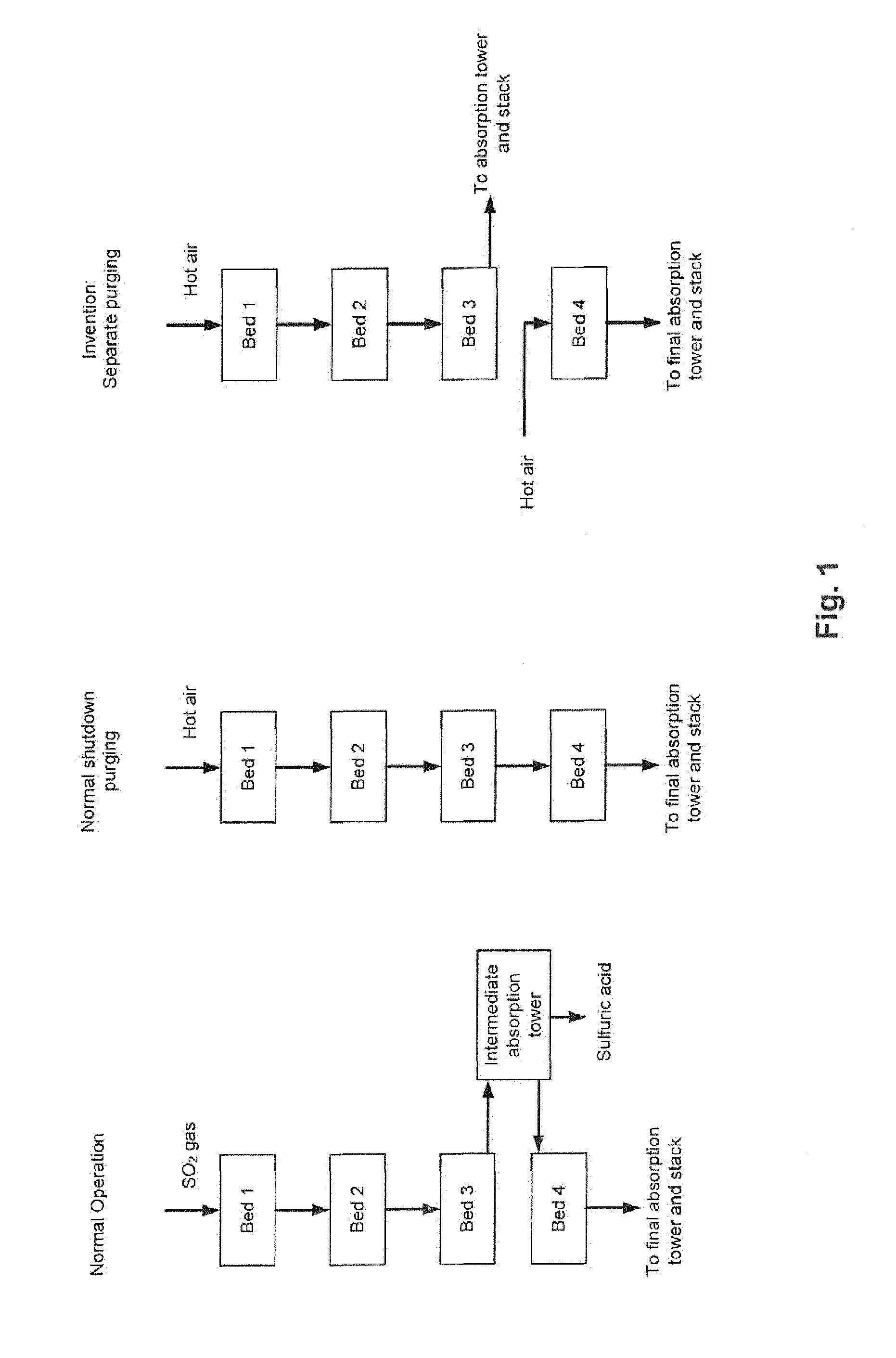
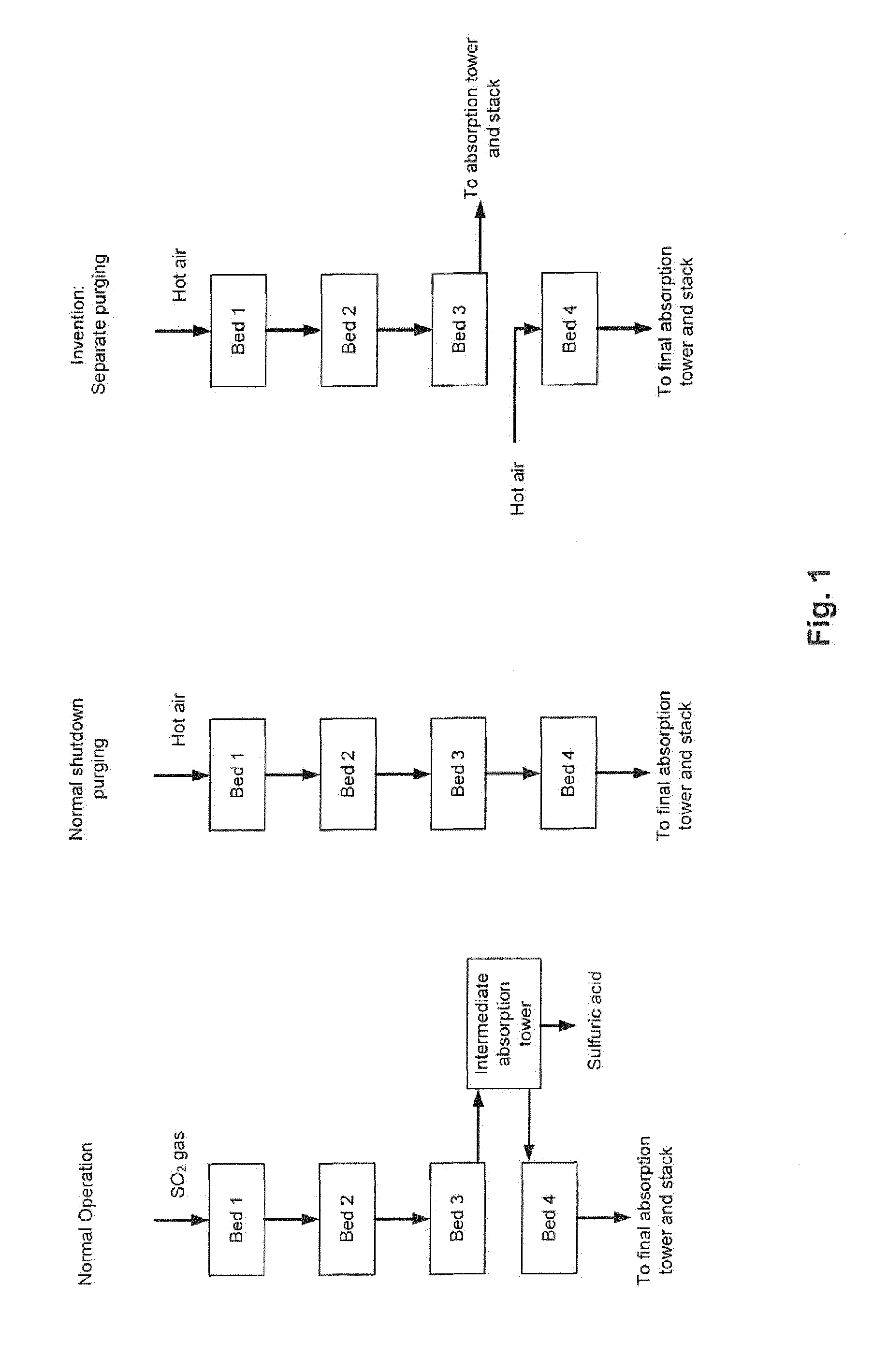
[0020] This separate purging, which constitutes the crux of the present invention, is illustrated in FIG. 1, which also illustrates the normal operation and the normal shut-down purging. All three situations are illustrated for a plant design comprising four catalyst beds (i.e. n=4).
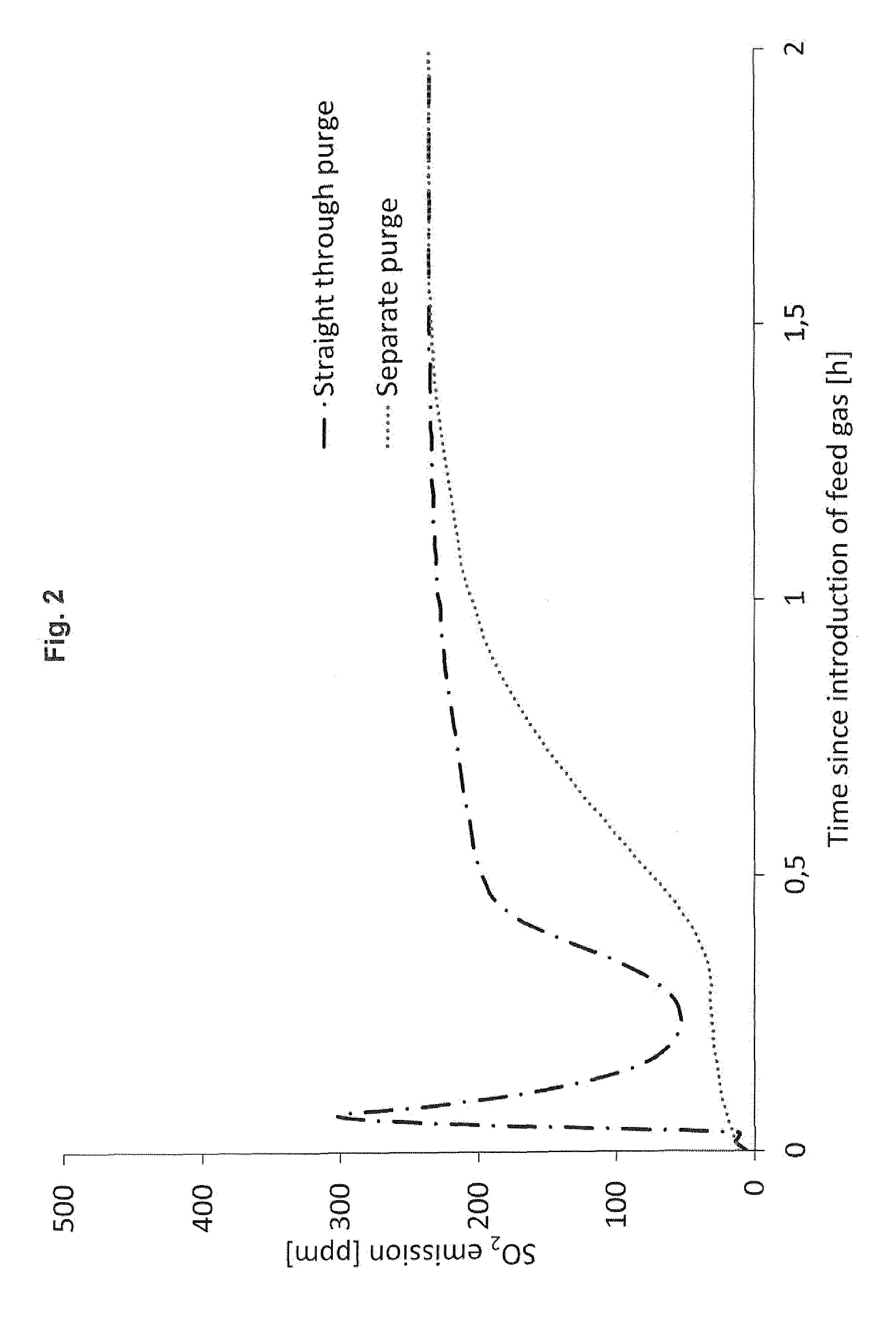
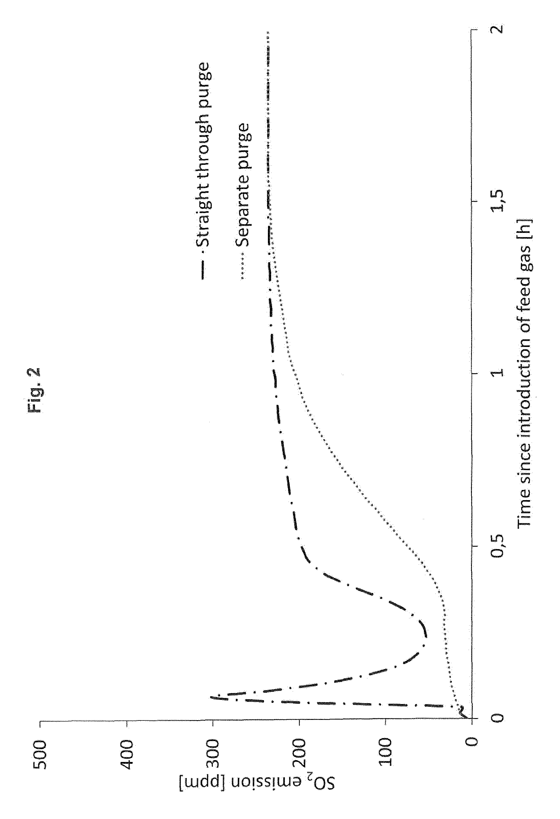
[0021] In FIG. 2, the separate purge according to the invention is compared to the straight-through purge of the prior art.
[0022] Normally, SO.sub.3 is purged from the catalyst during shut-down by passing hot air to the converter inlet and through all catalyst beds connected in series. The heat is primarily supplied by residual heat accumulated in the front-end of the plant (e.g. sulfur burner, boiler(s), ducting etc.). However, due to the above reaction (2), the SO.sub.3 released from the upper beds will accumulate in the final bed. If purging is not long enough, or if the temperatures are too low for reaction (2) to proceed to the left, then the SO.sub.3 desorption will cease. As a consequence, the concentration of free SO.sub.3 in the final bed is high at the next start-up, which will lead to SO.sub.3 emissions as described above.
[0023] In the process and the plant according to the invention, the shut-down procedure is changed. The hot air used for purging the upper catalyst beds is not sent to the final catalyst bed, but rather to an SO.sub.3 absorption tower before going to the stack. The final catalyst bed is purged separately with hot air, and as a result, the final bed desorbs SO.sub.3 and shifts reaction (2) to the left. During the next start-up, the sulfur-deficient final catalyst bed will act as a sulfur oxide filter and absorb both SO.sub.2 and SO.sub.3 due to reaction (2) and the reaction
SO.sub.2+1/2O.sub.2+A<->A.SO.sub.3+heat (3)
where A is a species in the melt which is able to chemically bind SO.sub.3 as mentioned earlier.
[0024] In this way the emissions of SO.sub.2 and SO.sub.3 are reduced during start-up, and the plant can be started up faster without violating SO.sub.2 and SO.sub.3 limits for transient operation.
[0025] The rate of reaction (1) is very low for vanadium-based catalysts at temperatures below 370-400.degree. C. depending on the specific catalyst type and gas composition. Now it has surprisingly been found that the rate of reaction (3) is high, even at low temperatures, for a sulfur-deficient catalyst which can remove SO.sub.2 at temperatures well below 350.degree. C.
[0026] Regarding the catalyst, a preferred catalyst comprises a vanadium(V) compound such as V.sub.2O.sub.5, sulfur in the form of sulfate, pyrosulfate, tri- or tetrasulfate and alkali metals, such as Li, Na, K, Rb or Cs, on a porous carrier. The porous carrier of the catalyst is preferably silicon dioxide (SiO.sub.2) with less than 10 wt %, preferably less than 5 wt %, more preferably less than 2 wt % and most preferably less than 1 wt % of alumina.
[0027] It is preferred that the alkali metal content of the catalyst is 2-25 wt %, more preferably 4-20 wt % and most preferably 8-16 wt %.
[0028] A preferred catalyst contains 1-15 wt %, preferably 2-12 wt % and most preferably 4-10 wt % of a vanadium(V) compound such as V.sub.2O.sub.5.
[0029] Further it is preferred that the catalyst contains 1-25 wt %, more preferably 2-20 wt % and most preferably 3-18 wt % sulfur in the form of sulfate, pyrosulfate, tri- or tetrasulfate. It is even more preferred that the catalyst contains 4-16 wt % sulfur, especially 4-10 wt % sulfur, in the form of sulfate, pyrosulfate, tri- or tetrasulfate.
[0030] It is preferred that the hot gas is air fed to the final bed at a temperature of 0-650.degree. C., preferably 400-600.degree. C.
[0031] The invention is illustrated further in the following example.
EXAMPLE
[0032] By using the method and the plant design according to the invention, the emissions of SO.sub.2 and SO.sub.3 are reduced during start-up, and the plant can be started up faster without violating SO.sub.2 and SO.sub.3 limits for transient operation. This reduction of emissions is illustrated in FIG. 2.
[0033] The basis of the example is a transient model for dynamic operation of an SO.sub.2 converter published by Sorensen et al. (Chemical Engineering Journal 278 (2015), 421-429). The mathematical model is capable of predicting the changes occurring in an SO.sub.2 converter due to changes in the operating conditions, because it can predict the dynamic changes in the temperature of the converter and the sulfur content of the catalyst.
[0034] In this example, a 3+1 double absorption plant is purged with 450.degree. C. for 8 hours before the air supply is turned off. The plant is subsequently assumed to be shut down for a non-specific period of time and the beds re-heated to temperatures of 550.degree. C., 460.degree. C., 420.degree. C. and 380.degree. C., respectively, prior to introduction of the SO.sub.2 feed gas.
[0035] The curves in FIG. 2 show the SO.sub.2 emission in ppm as a function of the time passed (in hours) for both the straight-through purge and the separate purge embodiment. It appears clearly from the curves that the straight-through purge causes a substantial SO.sub.2 emission immediately after introducing the feed gas. Within minutes after the feed gas introduction, the SO.sub.2 emission increases to 300 ppm, whereas the separate purge according to the invention leads to a much lower SO.sub.2 emission, especially during the first half hour following the feed gas introduction. Only after around 1.5 hours from the feed gas introduction, the two curves approach the same SO.sub.2 emission level.
* * * * *
D00001
D00002
D00003
D00004
XML
uspto.report is an independent third-party trademark research tool that is not affiliated, endorsed, or sponsored by the United States Patent and Trademark Office (USPTO) or any other governmental organization. The information provided by uspto.report is based on publicly available data at the time of writing and is intended for informational purposes only.
While we strive to provide accurate and up-to-date information, we do not guarantee the accuracy, completeness, reliability, or suitability of the information displayed on this site. The use of this site is at your own risk. Any reliance you place on such information is therefore strictly at your own risk.
All official trademark data, including owner information, should be verified by visiting the official USPTO website at www.uspto.gov. This site is not intended to replace professional legal advice and should not be used as a substitute for consulting with a legal professional who is knowledgeable about trademark law.