Surface Plate For Finish Polishing, Finish Polishing Device, And Polishing Method
Shimizu; Kenji
U.S. patent application number 16/076940 was filed with the patent office on 2019-02-14 for surface plate for finish polishing, finish polishing device, and polishing method. The applicant listed for this patent is JAPAN AGENCY FOR MARINE-EARTH SCIENCE AND TECHNOLOGY. Invention is credited to Kenji Shimizu.
| Application Number | 20190047111 16/076940 |
| Document ID | / |
| Family ID | 59625150 |
| Filed Date | 2019-02-14 |


| United States Patent Application | 20190047111 |
| Kind Code | A1 |
| Shimizu; Kenji | February 14, 2019 |
SURFACE PLATE FOR FINISH POLISHING, FINISH POLISHING DEVICE, AND POLISHING METHOD
Abstract
Provided is a finish polishing surface plate configured such that a polishing film is mounted thereon. The finish polishing surface plate includes a plate body having a planar surface; and a plurality of island shaped protrusions formed on the surface of the plate body. In the plurality of island shaped protrusions, continuous grooved recesses are formed between the respective island shaped protrusions.
| Inventors: | Shimizu; Kenji; (Yokosuka -shi, JP) | ||||||||||
| Applicant: |
|
||||||||||
|---|---|---|---|---|---|---|---|---|---|---|---|
| Family ID: | 59625150 | ||||||||||
| Appl. No.: | 16/076940 | ||||||||||
| Filed: | February 9, 2017 | ||||||||||
| PCT Filed: | February 9, 2017 | ||||||||||
| PCT NO: | PCT/JP2017/004746 | ||||||||||
| 371 Date: | August 9, 2018 |
| Current U.S. Class: | 1/1 |
| Current CPC Class: | B24B 37/14 20130101; B24B 37/16 20130101; B24B 37/042 20130101; B24B 37/044 20130101 |
| International Class: | B24B 37/16 20060101 B24B037/16; B24B 37/14 20060101 B24B037/14; B24B 37/04 20060101 B24B037/04 |
Foreign Application Data
| Date | Code | Application Number |
|---|---|---|
| Feb 15, 2016 | JP | 2016-026048 |
Claims
1. A finish polishing surface plate configured such that a polishing film is mounted thereon, the plate comprising: a plate body which has a planar surface; and a plurality of island shaped protrusions which is formed on the surface of the plate body, wherein in the plurality of island shaped protrusions, continuous grooved recesses are formed between the respective island shaped protrusions.
2. The finish polishing surface plate according to claim 1, wherein a diameter dimension of the island shaped protrusions is set within a range of 1.5 to 2.5 times a width dimension of the grooved recesses.
3. The finish polishing surface plate according to claim 1, wherein the island shaped protrusions adjacent to each other are arranged such that a separation distance therebetween is equal to the width dimension of the grooved recesses on the whole surface of the plate body.
4. The finish polishing surface plate according to claim 1, wherein each of the island shaped protrusions has a polygonal shape in plan view.
5. The finish polishing surface plate according to claim 1, wherein a diameter dimension of the island shaped protrusions is set within a range of 1/2 to 3/2 with respect to a diameter dimension of a polishing target surface of a polishing sample.
6. The finish polishing surface plate according to claim 1, wherein a polishing target surface of a polishing sample has regions having different hardnesses, and a Mohs hardness difference between a high-hardness region and a low-hardness region in the polishing target surface is 3 or more.
7. A finish polishing device comprising: the finish polishing surface plate according to claim 1; and a rotating device that rotates the finish polishing surface plate with respect to a rotational axis orthogonal to the surface of the plate body.
8. The finish polishing device according to claim 7, wherein the rotating device has a rotating plate that rotates around the rotational axis, and a holding part that holds the finish polishing surface plate to the rotating plate.
9. The finish polishing device according to claim 8, wherein the finish polishing surface plate is formed of stainless steel having magnetism, and wherein the holding part is capable of magnetizing the finish polishing surface plate.
10. A polishing method using the finish polishing device according to claim 1, the method comprising: performing polishing using a planar surface plate and polishing abrasive grains to generate edge sagging in a polishing sample; and performing polishing using the finish polishing device and a polishing film to eliminate the edge sagging to flatten the polishing target surface of the polishing sample.
11. The polishing method according to claim 10, wherein the polishing abrasive grains are alumina paste.
12. The finish polishing surface plate configured such that a polishing film is mounted thereon, wherein a diameter dimension of the island shaped protrusion is set within a range of 8 to 20 mm or 2 to 8 mm, and a diameter dimension of the grooved recesses is 1/2 of the diameter dimension of the island shaped protrusion.
Description
[0001] This application is a 371 National Stage Application of International Application No. PCT/JP2017/004746, filed on Feb. 9, 2017, published as International Publication No. WO 2017/141812, which claims priority to Japanese Patent Application No. 2016-026048, filed Feb. 15, 2016, the content of which is incorporated herein by reference.
TECHNICAL FIELD
[0002] The present invention relates to a surface plate for finish polishing, a finish polishing device, and a polishing method.
BACKGROUND ART
[0003] In the related art, as polishing devices in which a polishing film is provided on a surface plate, there are known a polishing device in which the polishing film is fixed to the surface plate via an elastic body on the surface plate, and a polishing device in which the polishing film is directly fixed to the surface plate. These well-known polishing devices are disclosed, for example, in Patent Document 1. Patent Document 1 discloses a polishing device in which two types of polishing films including a polishing film for rough processing and a polishing film for finish polishing are mounted on a polishing surface plate, and an elastic body is mounted between the polishing target surface plate and the polishing film if necessary.
[0004] In a case where the elastic body is mounted between the polishing target surface plate and the polishing film or in a case where a polishing cloth having loose abrasive grains dispersed thereon is used, an edge sagging may be caused. The edge sagging is a phenomenon in which a soft part of a polishing sample may be excessively polished and excavated, and a circumferential edge of a hard part surrounded by the soft part may also be excessively polished. Particularly in a case where polishing is performed with the loose abrasive grains interposed, the edge sagging is likely to occur.
[0005] If a film of lubricant, such as water, is thick in a case where a fixed abrasive grain film is mounted on a smooth polishing surface plate, there is a concern that the lubricant may be interposed between the fixed abrasive grain film and the polishing sample and polishing may not be performed. Additionally, there is also a concern that the polishing target surface of the polishing sample may be sucked to the fixed abrasive grain film like a suction cup and polishing may not be easy. Moreover, there is also a concern that shavings may enter between the polishing target surface of the polishing sample and the fixed abrasive grain film and may damage the polishing target surface of the polishing sample.
[0006] As a technique of solving these problems, Patent Document 2 discloses a finishing polishing surface plate in which a number of grooves, having a width of several millimeters, parallel to a planar glass plate are formed.
CITATION LIST
Patent Literature
[0007] [Patent Document 1] Japanese Unexamined Patent Application, First Publication No. 2007-185754 [0008] [Patent Document 2] Japanese Patent No. 5317095
SUMMARY OF INVENTION
Technical Problem
[0009] A polishing wrapping film disclosed in the above Patent Document 1 and Patent Document 2 is a film that is sufficient in smoothly polishing materials. On the other hand, in a case where a flat polishing sample is made using the polishing wrapping film, the polishing wrapping film is placed on a hard plate (glass plate) having high planarity, and the sample is manually polished while causing the lubricant, such as water, flow to the polishing wrapping film. In this case, as the degree of the abrasive grains becomes smaller, the sample to be polished and the film are brought into closer contact with each other, and resistance increases. Accordingly, there is a case where the polishing sample may not smoothly slide on the polishing film and may not be cleanly polished. As the polishing target surface of the polishing sample becomes larger, it is noticeable that the polishing sample does not smoothly slide on the polishing film.
[0010] Additionally, there is a case where a lot of scratches may be formed on the polishing target surface of the polishing sample due to shavings. As the polishing target surface of the polishing sample becomes larger, the scratches become conspicuous.
[0011] Moreover, in Patent Document 2, particularly as the polishing target surface of the polishing sample becomes larger for manual polishing, there is a concern that prolonged work is required for mirror-finishing the sample. For that reason, there is a demand to shorten the time required for the mirror finishing.
[0012] Additionally, due to polishing in a certain direction (length), in manual polishing, a skillful technique is required for evenly polishing the sample surface. For this reason, particularly as the polishing target surface of the polishing sample becomes larger, there is a case where a polishing state may change depending on a worker's skill level.
[0013] Additionally, in a case where the above-described edge sagging has occurred and in a case where the polishing target surface of the polishing sample is analyzed by secondary ion mass spectroscopy (SIMS), there is a case where the flatness of an analysis surface (polishing target surface) may be insufficient, and the analysis may not be performed well. For this reason, particularly as the polishing target surface of the polishing sample becomes larger, there is a concern that analysis processing time may increase.
[0014] Additionally, if the polishing sample is small, time relating to flattening processing by polishing is also short. On the other hand, since there is a concern that the time related to flattening processing by polishing may become long if the polishing sample is large, there is demand to shorten this time. Moreover, if the polishing sample becomes large, the flattening processing by polishing will become difficult. As a result, the efficiency and accuracy of the sample making will be dependent on a worker's skill level. For that reason, there is a demand to eliminate the dependability onto the worker's skill level.
[0015] The present invention has been made in view of the above situation to achieve the following objects. [0016] 1. Elimination of edge sagging. [0017] 2. Suppression of uneven polishing or the like in each region resulting from hardness difference. [0018] 3. Suppression of sticking of polishing sample to polishing device. [0019] 4. Suppression of damage to polishing target surface of polishing sample. [0020] 5. Suppression of damage of polishing film. [0021] 6. Adaptation to large polishing sample. [0022] 7. Elimination of dependability on worker's skill level.
Solution to Problem
[0023] A finish polishing surface plate related to a first aspect of the present invention is configured such that a polishing film is mounted thereon. The finish polishing surface plate includes a plate body having a planar surface; and a plurality of island shaped protrusions formed on the surface of the plate body. In the plurality of island shaped protrusions, continuous grooved recesses are formed between the respective island shaped protrusions.
[0024] A diameter dimension of the island shaped protrusions may be set within a range of 1.5 to 2.5 times a width dimension of the grooved recesses.
[0025] The island shaped protrusions adjacent to each other may be arranged such that a separation distance therebetween is equal to the width dimension of the grooved recesses on the whole surface of the plate body.
[0026] Each of the island shaped protrusions may have a polygonal shape in plan view.
[0027] A diameter dimension of the island shaped protrusions may be set within a range of 1/2 to 3/2 with respect to a diameter dimension of a polishing target surface of a polishing sample.
[0028] A polishing target surface of a polishing sample may have a region having different hardnesses, and a Mohs hardness difference between a high-hardness region and a low-hardness region in the polishing target surface may be 3 or more.
[0029] A finish polishing device related to a second aspect of the present invention includes the finish polishing surface plate related to the first aspect; and a rotating device that rotates the finish polishing surface plate with respect to a rotational axis orthogonal to the surface of the plate body.
[0030] The rotating device may have rotating plate that rotates around the rotational axis, and a holding part that holds the finish polishing surface plate to the rotating plate.
[0031] The finish polishing surface plate may be formed of stainless steel having magnetism, and the holding part may be capable of magnetizing the finish polishing surface plate.
[0032] A polishing method related to a third aspect of the present invention includes performing polishing using a planar surface plate and polishing abrasive grains to generate edge sagging in a polishing sample; and performing polishing using the finish polishing device related to the above second aspect and a polishing film to eliminate the edge sagging to flatten the polishing target surface of the polishing sample.
[0033] According to the finish polishing surface plate related to the first aspect, since the continuous grooved recesses are formed between the respective island shaped protrusions in the plurality of island shaped protrusions, it is possible to efficiently exhibit a drainage effect from the grooved recesses extending in multiple directions rather than one direction. For that reason, it is possible to improve the ease of drainage of lubricant, such as water. The polishing target surface of the polishing sample and the polishing film can easily come into contact with each other, and polishing efficiency can be improved. Additionally, since shavings generated from the polishing sample are easily discharged to the outside of a working plane via the grooved recesses of the surface plate, a frequency at which the polishing target surface is damage can be remarkably lowered.
[0034] Additionally, since the island shaped protrusions are split by the grooved recesses, edge parts of the island shaped protrusions corresponding to regions to be subjected to polishing extend in the multiple directions rather than one direction. As a result, even in a case where the polishing target surface has regions having different hardnesses, it is possible to prevent occurrence of sagging.
[0035] Simultaneously, since the island shaped protrusions are split by the grooved recesses extending in the multiple directions rather than one direction, it is possible to prevent a situation where the polishing target surface of the polishing sample and the polishing film may be brought into close contact with each other and polishing may not be performed, when the polishing target surface of the polishing sample and the polishing film perform polishing by moving relative to each other.
[0036] Additionally, since the drainage of the lubricant is easily performed by the grooved recesses, the polishing target surface of the polishing sample and the polishing film can easily come into contact with each other, the polishing efficiency can be performed, and the processing time can be shortened even in a case where the polishing target surface of the polishing sample becomes large.
[0037] Additionally, in the finish polishing surface plate related to the first aspect, since the diameter dimension of the island shaped protrusions is set within a range of 1.5 to 2.5 times the width dimension of the grooved recesses, the drainage of the lubricant, prevention of sticking of the polishing sample, and prevention of the sagging can be effectively realized.
[0038] Additionally, in the finish polishing device related to the first aspect, since the separation distance between the island shaped protrusions adjacent to each other is equal to the width dimension of the grooved recesses on the whole surface of the plate body, the drainage of the lubricant, prevention of sticking of the polishing sample, and prevention of the sagging can be effectively realized.
[0039] Additionally, in the finish polishing surface plate related to the first aspect, since the shapes of the island shaped protrusions in plan view are the polygonal shapes, the drainage of the lubricant, and the island shaped protrusions are split by the grooved recesses extending in the multiple directions rather than one direction, the drainage of the lubrication, prevention of sticking of the polishing sample, and prevention of the sagging can be effectively realized.
[0040] Additionally, in the finish polishing surface plate related to the first aspect, since the diameter dimension of the island shaped protrusions is set within a range of 1/2 to 3/2 with respect to the diameter dimension of the polishing target surface of the polishing sample, the drainage of the lubricant, prevention of sticking of the polishing sample, and prevention of the sagging can be effectively realized.
[0041] Additionally, in the finish polishing device related to the first aspect, even in a case where the polishing target surface of the polishing sample has regions having different hardnesses, and the Mohs hardness difference between the high-hardness region and the low-hardness region in the polishing target surface is 3 or more, the drainage of the lubricant, prevention of sticking of the polishing sample, and prevention of the sagging can be effectively realized.
[0042] Additionally, since the finish polishing device related to the above second aspect includes the finish polishing surface plate related to the first aspect; and the rotating device that rotates the finish polishing surface plate with respect to the rotational axis orthogonal to the surface of the plate body, polishing can be performed by changing a state where the polishing target surface of the polishing sample and the polishing film come into contact with each other. For that reason, ease of drainage of the lubricant can be further improved using rotation, and prevention of sticking of the polishing sample and prevention of the sagging can be effectively realized.
[0043] Additionally, in the finish polishing device related to the first aspect, since the rotating device has the rotating plate that rotates around the rotational axis, and the holding part that holds the finish polishing surface plate to the rotating plate, the drainage of the lubricant, prevention of sticking of the polishing sample, and prevention of the sagging can be effectively realized. Accordingly, it is possible to perform polishing processing without being dependent on a worker's skill level.
[0044] Additionally, in the finish polishing device related to the first aspect, since the finish polishing surface plate is formed of stainless steel having magnetism, and the holding part is capable of magnetizing the finish polishing surface plate, ease of replacement of the polishing film and close contact of the polishing film with the surface plate can be improved.
[0045] Additionally, the polishing method related to the third aspect of the present invention includes performing polishing using a planar surface plate and polishing abrasive grains to generate edge sagging in a polishing sample; and performing polishing using the finish polishing device related to the second aspect and a polishing film to eliminate the edge sagging to flatten the polishing target surface of the polishing sample. Additionally, the polishing abrasive grains may be alumina paste. Accordingly, since the amount (surface area) of the polishing sample to be cut with the polishing film can be made small, it is possible to further shorten working hours required for flattening to quickly perform polishing by the planar surface plate and polishing abrasive grains.
[0046] Therefore, since further gaps can also be formed between the polishing film and the polishing sample, the shavings are not easily brought into contact with the polishing target surface, and can also be easily discharged, thereby reducing a rate at which a sample surface is damaged.
Advantageous Effects of Invention
[0047] According to the above aspects of the present invention, the occurrence of the sagging in the polishing sample can be prevented. Additionally, occurrence of uneven polishing or the like in each region resulting from a hardness difference on the polishing target surface of the polishing sample can be prevented. Additionally, the sticking of the polishing sample to the polishing film can be prevented. Additionally, occurrence of the damage on the polishing target surface resulting from the shavings can be prevented. Additionally, damage of the polishing film by the sticking or other causes can be prevented. Additionally, the possibility of coping with the size of the polishing sample can be realized, and producing the polishing sample without depending on a worker's skill level can be realized.
BRIEF DESCRIPTION OF DRAWINGS
[0048] FIG. 1 is a plan view illustrating a finish polishing surface plate related to a first embodiment of the present invention.
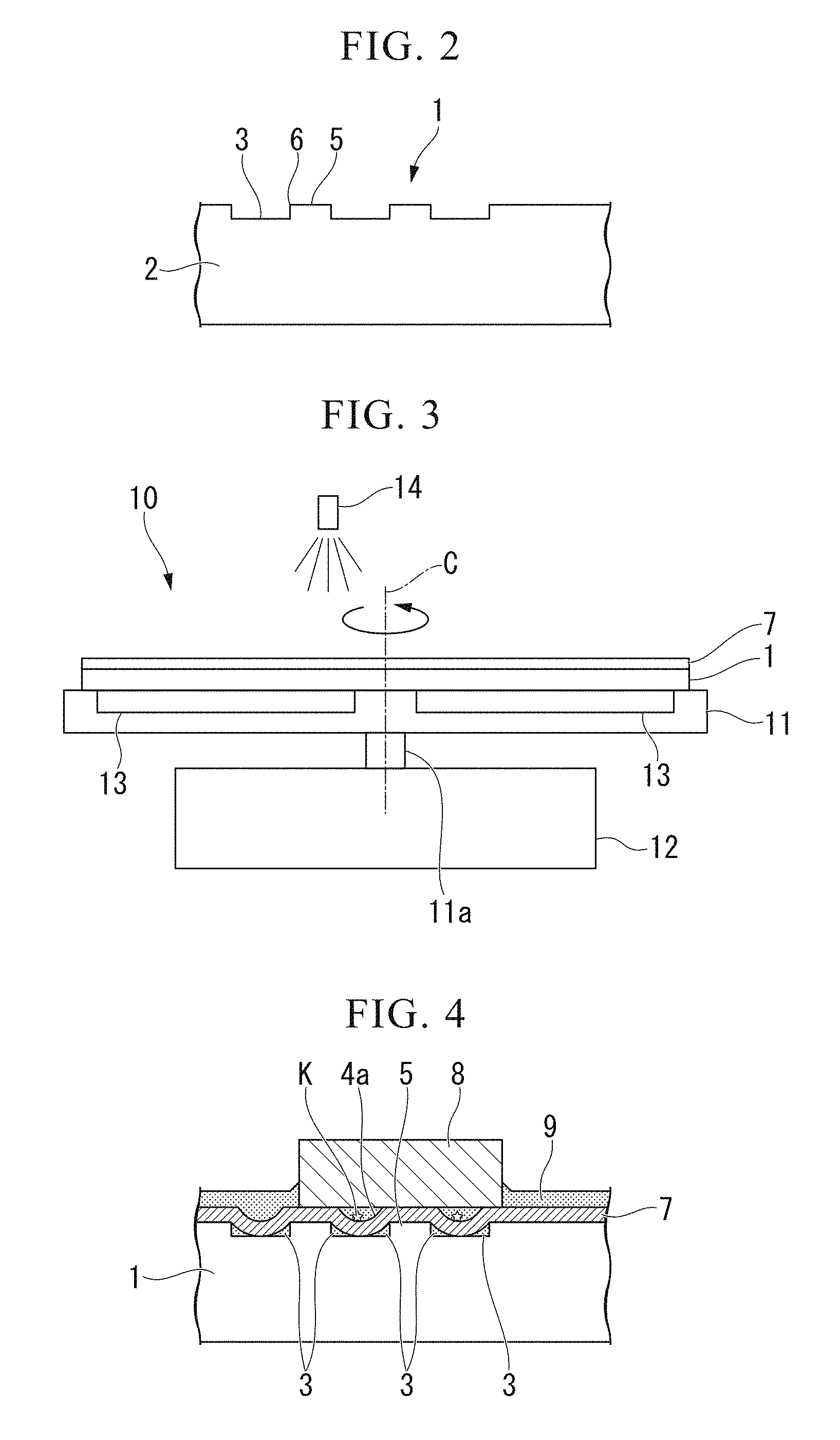
[0049] FIG. 2 is an enlarged sectional view illustrating the finish polishing surface plate related to the first embodiment of the present invention.
[0050] FIG. 3 is a schematic front view illustrating the finish polishing device related to the first embodiment of the present invention.
[0051] FIG. 4 is a view illustrating a state where a polishing film including a fixed abrasive grain film is mounted on the finish polishing device related to the first embodiment of the present invention to polish a polishing sample.
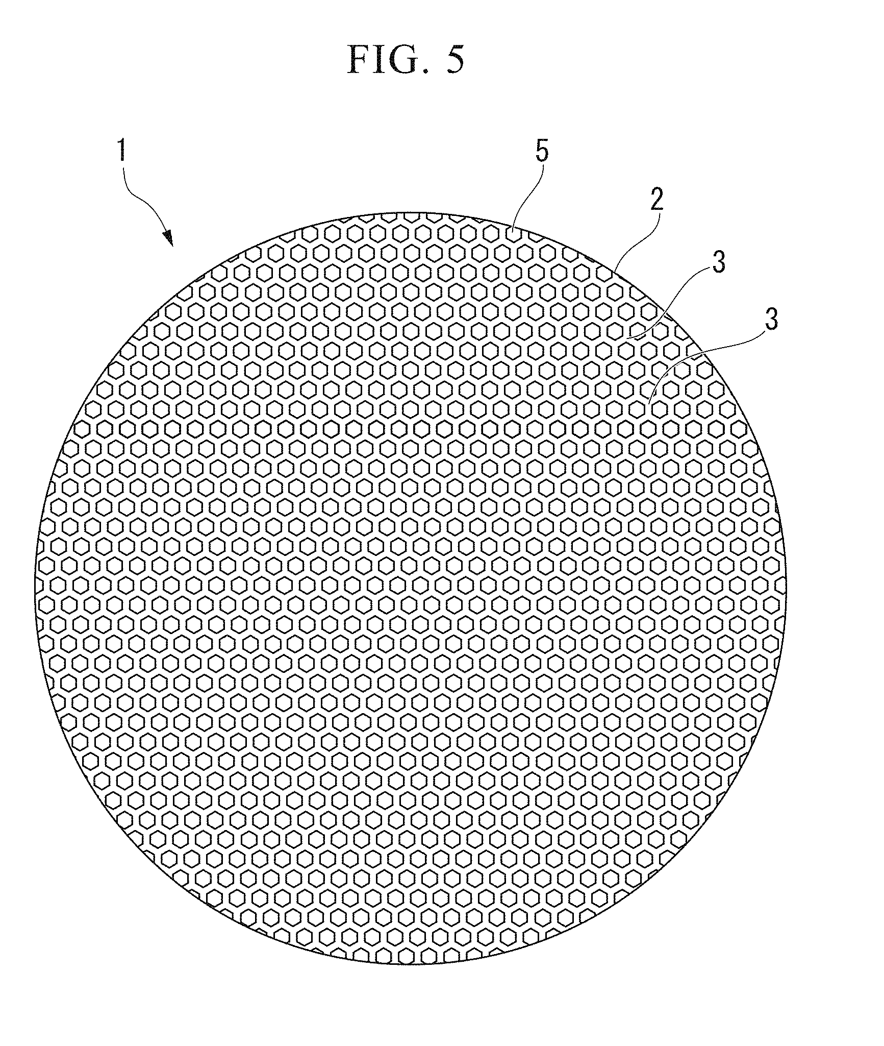
[0052] FIG. 5 is a plan view illustrating a finish polishing surface plate related to a second embodiment of the present invention.
[0053] FIG. 6 is an image illustrating a sample polishing target surface polished by the finish polishing surface plate related to the embodiment of the present invention.
[0054] FIG. 7 is an image illustrating a sample polishing target surface polished by the finish polishing surface plate related to the embodiment of the present invention.
[0055] FIG. 8 is an image illustrating a sample polishing target surface polished by the finish polishing surface plate related to the embodiment of the present invention.
[0056] FIG. 9 is an image illustrating a sample polishing target surface polished by the finish polishing surface plate related to the embodiment of the present invention.
DESCRIPTION OF EMBODIMENTS
[0057] Hereinafter, a finish polishing surface plate and a finish polishing device related to a first embodiment of the present invention will be described with reference to the drawings. The present invention is not to be interpreted as being limited to this, and various changes, modifications, and improvements can be made on the basis of the knowledge of those skilled in the art without departing from the scope of the present present invention.
[0058] FIG. 1 is a plan view of the finish polishing surface plate related to the present embodiment. FIG. 2 is an enlarged sectional view illustrating the finish polishing surface plate related to the present embodiment. FIG. 3 is a schematic front view illustrating the finish polishing device in the present embodiment.
[0059] A finish polishing surface plate 1 related to the present embodiment is used when polishing a composite material with different hardnesses to form a thin sample piece. As shown in FIGS. 1 and 2, for example, a plurality of island shaped protrusion 5, and grooved recesses 3 that are continuously provided between the island shaped protrusions 5 are provided on the surface of a plate body 2.
[0060] In the present embodiment, the plate body 2 has a flat disk shape. As the plate body 2, for example, a metal plate or the like having well-known magnetism can be used. It is preferable that the plate body 2 is formed of a stainless plate having magnetism. The size of the plate body 2 is .PHI.100 to 300 mm and particularly preferably about .PHI.150 mm (.+-.15 mm) or 200 mm (.+-.20 mm). Additionally, the thickness of the plate body 2 is 1.5 to 3 mm and particularly preferably about 2 mm (.+-.0.2 mm). Additionally, SUS 200 series can be applied.
[0061] As shown in FIGS. 1 and 2, the island shaped protrusions 5 have a regular hexagonal shape in plan view, and the individual island shaped protrusions 5 are arranged to be densest in a mutually separated state.
[0062] A diameter dimension T1 of each island shaped protrusion 5 can be set to correspond to the size of a polishing target surface in a polishing sample 8. For example, T1 can be set to a range of 1/2 to 3/2 with respect to the diameter dimension of the sample polishing target surface (polishing target surface) of the polishing sample 8. Specifically, the diameter dimension T1 of the island shaped protrusion 5 can be set to about 12 mm (.+-.1.2 mm) within a range of 8 mm to 20 mm. In addition, the diameter dimension T1 of the island shaped protrusion 5 is a distance between opposed sides of the island shaped protrusion 5.
[0063] Separation distances between adjacent island shaped protrusions 5 (distances between opposed sides of two adjacent island shaped protrusions 5) may be equal to each other. In addition, although the profiles of the island shaped protrusions 5 are not hexagonal shapes in portions that interferes with an edge part of the plate body 2, these portions may be formed such that separation distances between adjacent island shaped protrusions 5 are equal to each other.
[0064] Although the planar profiles of the island shaped protrusions 5 have a regular hexagonal shape in the present embodiment, the planar profiles are not limited to this as long as the island shaped protrusions are arranged on a plane in the closest state. A circular shape, an elliptical shape, or a polygonal shape with a larger number of corners than 6 can also be adopted. In this case, although the width of each grooved recess 3 to be described below becomes uneven depending on locations, the arrangement state of the island shaped protrusion 5 may be maintained in the same manner as in the case of the regular hexagonal shape.
[0065] At the profile position of each island shaped protrusion 5, an end part of the island shaped protrusion 5 is formed in a state where the grooved recess 3 is formed by polishing, that is, in a state where the end part is cut upright such that a side surface of the island shaped protrusion 5 or the grooved recess 3 is equal to a normal direction of a principal surface of the plate body 2.
[0066] As shown in FIGS. 1 and 2, the grooved recess 3 is formed between the two adjacent island shaped protrusions 5 and is provided such that a width dimension T2 of the grooved recess 3 is equal to the separation distance between the island shaped protrusions 5. The widths dimensions T2 of the grooved recesses 3 may be set to be equal to each other on the whole surface of a working plane of the plate body 2 and may be set to be equal to about half of the diameter dimension T1 of the island shaped protrusion 5. Specifically, the width dimension T2 of each grooved recess 3 can be about 6 mm (.+-.0.6 mm) within a range of 4 mm to 10 mm.
[0067] Additionally, the grooved recess 3 is engraved such that the depth dimension from a top part of the island shaped protrusion 5 is within a range of 50 to 300 .mu.m, preferably about 100 to 200 .mu.m (.+-.10 .mu.m). The grooved recess 3 extends between the island shaped protrusion 5 and island shaped protrusion 5 adjacent to each other, and all the grooved recesses 3 are brought into a continuous state on the surface of the plate body 2.
[0068] The grooved recesses 3 can be formed on the surface of the plate body 2 made of metal by well-known methods, such as etching, polishing, and cutting.
[0069] A corner part 6 of a boundary line between each grooved recess 3 and each island shaped protrusion 5 can also be formed by rounding off a corner to the same extent as a curvature radius that is half of the depth of the grooved recess 3.
[0070] Although a polishing film 7 mounted on the finish polishing surface plate 1 in the present embodiment is not particularly described, for example, a well-known fixed abrasive grain film for finishing application having an abrasive grain diameter of about 0.3 .mu.m to 3 .mu.m is used.
[0071] The present embodiment can also be applied to the polishing sample 8 in which a polishing target surface has regions having different hardnesses, and a Mohs hardness difference between a high-hardness region and a low-hardness region in this polishing target surface is 3 or more. If there is a hardness difference on the polishing target surface, sagging is likely to occur. However, in the finish polishing surface plate 1 of the present embodiment, polishing can be suitably performed even in such a polishing sample.
[0072] Additionally, the high-hardness region has a Mohs hardness of about 4 to 8 and can include glass, a mineral, metal, or the like, and the low-hardness region can include a mineral or the like having a lower viscosity than resin. The low-hardness region has a Mohs hardness of about 1 to 3 and can include indium.
[0073] The polishing sample includes, for example, a sample in which a plurality of polishing samples, such as rock, are embedded on a surface of a resinous cylindrical base material having a diameter dimension of about 25 mm.
[0074] As shown in FIG. 3, the finish polishing device 10 in the present embodiment has, as a rotating device that rotates the finish polishing surface plate 1 with a rotational axis C orthogonal to the principal surface (horizontal plane) used as the working plane at the time of polishing as a center, a rotating plate 11 that rotates around the rotational axis C, and a driving source 12, such as a motor, which rotates the rotating plate 11. Additionally, the finish polishing device 10 has, as a holding part that holds the finish polishing surface plate 1 to the rotating plate 11, a magnetizing part 13 that is capable of magnetizing the finish polishing surface plate 1 and is provided for fixing the finish polishing surface plate 1 to the rotating plate 11. Moreover, the finish polishing surface plate 1 has a supply part 14 that can supply lubricant 9, such as water, from above the rotating plate 11 to the working plane.
[0075] As shown in FIG. 3, the rotating plate 11 is a disk that has a diameter approximately equal to the finish polishing surface plate 1 or is larger than the finish polishing surface plate 1 and has an upper surface formed as a flat surface in which the magnetizing part 13 is embedded. The rotating plate 11 is connected to the driving source 12 via a rotating mechanism 11a, and the rotating mechanism 11a is erected at a center position of a lower surface of the rotating plate 11.
[0076] As shown in FIG. 3, the magnetizing part 13 can be electromagnet that is flush with an upper surface of the rotating plate 11 and is capable of switching ON/OFF of magnetization. Additionally, the magnetizing part 13 may be an anisotropic rubber magnet sheet which is provided with a uniform thickness on the entire surface of the rotating plate 11 and in which an upper surface is a flat surface.
[0077] As shown in FIG. 4, the finish polishing device 10 places the finish polishing surface plate 1 mounted with the polishing film 7 on the rotating plate 11 to rotate the rotating plate 11 by the driving source 12. Along with this, polishing processing is performed by supplying the lubricant 9 from the supply part 14 to an upper surface of the polishing film 7 to push the polishing sample 8 against the polishing film 7. Accordingly, excessive lubricant 9 is discharged from any continuous grooved recesses 3 on the entire working plane of the plate body 2, the polishing film 7 is sunken along the shapes of the grooved recesses 3 in the portions of the grooved recesses 3 of the finish polishing surface plate 1, and arcuate recesses 4a having a shape corresponding to the shape of each grooved recess 3 is formed in the surface of the polishing film 7.
[0078] In this way, for example, excessive lubricant 9, such as water, on the working plane of the plate body 2 is discharged from the working plane of the plate body 2 by the grooved recesses 3 and the arcuate recesses 4a formed in the surface of the polishing film 7. Accordingly, the lubricant 9 is not substantially interposed between the polishing target surface of the polishing sample 8 and the polishing film 7 immediately above the island shaped protrusions 5. Accordingly, the polishing target surface of the polishing sample 8 and the polishing film 7 can easily come into contact with each other above the island shaped protrusions 5, and polishing efficiency can be improved.
[0079] Additionally, since the contact area between the polishing target surface of the polishing sample 8 and the polishing film 7 is limited by the formation of the arcuate recesses 4a. Therefore, suction of the polishing target surface of the polishing sample 8 to the polishing film 7 is suppressed. Therefore, an acting force required for the polishing can be reduced, and polishing processing time can be shortened. Moreover, since shavings K generated from the polishing sample 8 accumulates within the arcuate recesses 4a of the polishing film or are discharged to the outside via the arcuate recesses 4a, the frequency at which the shavings K damages the polishing target surface decreases remarkably.
[0080] Even in a case where the polishing sample 8 made of a composite material having a hardness difference on the polishing target surface is polished, it is possible to prevent sagging or prevent partial variation of a polishing state to realize polishing having planarity and flatness.
[0081] According to the present embodiment, even if the operation skill level is low, it is possible to easily produce a polishing sample 8 having high planarity and flatness in a short time. Therefore, the possibility that the polishing sample 8 itself is damaged can be reduced, and the present embodiment can also be applied to a valuable sample without alternatives, such as a single article.
[0082] Hereinafter, a finish polishing surface plate related to a second embodiment of the present invention will be described with reference to a drawing.
[0083] FIG. 5 is a plan view illustrating a finish polishing surface plate related to the present embodiment.
[0084] The present embodiment is different from the above-described first embodiment in terms of the dimensions of the island shaped protrusions 5 and the grooved recesses 3, and corresponding constituent elements other than this will be designated by the same reference signs and the description thereof will be omitted.
[0085] In the present embodiment, the width T2 of each grooved recess 3 is made smaller than the diameter T1 of each island shaped protrusion 5, and the diameter T1 of the island shaped protrusion 5 can be set to about 4 mm (.+-.4 mm) within a range of 2 to 8 mm.
[0086] The width T2 of the grooved recess 3 is provided so as to be equal to a separation distance between two adjacent island shaped protrusions 5. The widths T2 of the grooved recesses 3 are equal to each other on the whole surface of the working plane of the plate body 2. Specifically, the width T2 of each grooved recess 3 can be set to about 2 mm (.+-.0.2 mm) within a range of 1 to 4 mm.
[0087] The present embodiment can also be applied to the polishing sample 8 in which a polishing target surface has regions having different hardnesses and a Mohs hardness difference between a high-hardness region and a low-hardness region in this polishing sample surface is 3 or more. If there is a hardness difference on the polishing target surface, sagging is likely to occur. However, in the finish polishing surface plate 1 of the present embodiment, polishing can be suitably performed even in such a polishing sample.
[0088] The present embodiment can also be applied to, for example, a polishing sample in which a plurality of polishing samples, such as rock, are embedded on a surface of a resinous cylindrical base material having a diameter of about 5 to 10 mm.
[0089] In the present embodiment, polishing can be performed so as to correspond to a polishing sample 8 smaller than the polishing sample 8 in the first embodiment by setting the width T2 of the grooved recess 3 and the diameter T1 of the island shaped protrusion 5 as described above.
[0090] Additionally, in the present embodiment, first, a first polishing step is performed by supplying alumina paste to a surface plate without the ordinary grooved recesses 3, and then, a second polishing step is performed using the finish polishing surface plate 1 and the polishing film 7 of the present embodiment.
[0091] In the first polishing step, the processing of forming a polishing target surface having area and flatness sufficient to perform finish polishing on the polishing sample 8 is performed. On the other hand, in a case where the high-hardness region and the low-hardness region having different hardnesses on the polishing target surface are included because the surface plate having no grooved recesses 3 and island shaped protrusions 5 are included on the working plane, there is a case where the sagging may occur. Additionally, there is a case where the low-hardness region may be excessively polished.
[0092] However, in the present embodiment, by performing the second polishing step after the first polishing step, the amount (surface area) of the polishing sample to be cut with the polishing film can be made small by the first polishing step (first step), and flattening can be made by the second polishing step (second step). Accordingly, it is possible to further shorten working hours to quickly perform polishing.
[0093] Additionally, gaps resulting from the further arcuate recesses can also be formed between the polishing film 7 and the polishing sample 8. Therefore, the shavings K are not easily brought into contact with the polishing target surface and can also be easily discharged, thereby reducing a rate at which a sample surface is damaged.
Examples
[0094] Hereinafter, examples related to the present invention will be described.
[0095] FIG. 6 is an image illustrating a polishing sample obtained by performing the first step in the second embodiment, using a surface plate having no grooved recesses 3.
[0096] Here, polishing processing was performed, using 0.3 .mu.m alumina paste as loose abrasive grains. As shown in FIG. 6, it can be seen that remarkable edge sagging occurs due to a difference in material hardness.
[0097] In addition, in FIG. 6, the hardnesses in the polishing sample are hardnesses: clay mineral (black portion)<volcanic glass (light grey color)<pyrogenetic mineral (white polygonal portion).
[0098] FIG. 7 shows an image illustrating a polishing sample obtained by performing the second step in the second embodiment on the polishing sample shown in FIG. 6, using the finish polishing surface plate 1.
[0099] Here, after polishing was performed for 1 minute in a state where the rotating plate 11 was rotated at 300 rpm using one having an abrasive grain diameter of 3 .mu.m as a polishing film (wrapping film), finish polishing was performed for 2 minutes in a state where the rotating plate 11 was rotated at 300 rpm using one having an abrasive grain diameter of 0.5 .mu.m as a polishing film (wrapping film).
[0100] As shown in FIG. 7, it can be seen that, even if there is a difference in material hardness, sagging does not occur and the sample is flattened.
[0101] FIG. 8 is an image illustrating a polishing sample obtained by performing the first step in the second embodiment, using a surface plate having no grooved recesses 3.
[0102] Here, polishing processing was performed, using 0.3 .mu.m alumina paste as loose abrasive grains. As shown in FIG. 8, it can be seen that remarkable edge sagging occurs due to a difference in material hardness.
[0103] In addition, in FIG. 8, the hardnesses in the polishing sample are hardnesses: clay mineral (black portion)<volcanic glass (light grey color)<pyrogenetic mineral (white polygonal portion).
[0104] FIG. 9 shows an image illustrating a polishing sample obtained by performing the second step on the polishing sample shown in FIG. 8, using the finish polishing surface plate 1 in the above-described second embodiment.
[0105] Here, polishing was performed for 3 minutes in a state where the rotating plate 11 was rotated at 300 rpm, using one having an abrasive grain diameter of 0.5 .mu.m as a polishing film (wrapping film).
[0106] As shown in FIG. 9, it can be seen that, even if there is a difference in material hardness, sagging does not occur and the sample is flattened.
[0107] In addition, those including a pyroxene (Mohs hardness 6.5 to 7) olivines (Mohs hardness 7) spinel (Mohs hardness 8) indium metal (Mohs hardness 1.2) kaolinite; or clay (Mohs hardness 1-2) iron nickel alloy (Mohs hardness 4) can be included as the polishing sample 8.
[0108] From these results, it can be seen that sufficient planarizing and flattening can be realized for a polishing sample subjected to the second step using the finish polishing surface plate 1 in the embodiment.
[0109] Accordingly, it is possible for the polishing sample 8 flattened in the present invention to sufficiently satisfy smoothness required for application to SIMS (secondary ion mass spectroscopy). Specifically, a state where a sample surface can be suitably observed using an objective lens (Nikon L Plan 2.5.times.0.075 EPI) having a relatively shallow depth of focus with reflected light of a polarization microscope that is a criterion for determining whether or not analysis performed by the SIMS is possible can be satisfied.
INDUSTRIAL APPLICABILITY
[0110] The present invention makes it possible to quickly and smoothly polish a composite material having remarkably different hardnesses, and can be widely utilized in individual fields involved in processing of hard-to-work materials, including the materials science field.
REFERENCE SIGNS LIST
[0111] 1: FINISH POLISHING SURFACE PLATE [0112] 2: PLATE [0113] 3: GROOVED RECESS [0114] 4A: ARCUATE RECESSES [0115] 5: ISLAND SHAPED PROTRUSION [0116] 6: CORNER PART [0117] 7: POLISHING FILM [0118] 8: POLISHING SAMPLE [0119] 9: LUBRICANT [0120] 10: FINISH POLISHING DEVICE [0121] 11: ROTATING PLATE [0122] 11A: ROTATING MECHANISM [0123] 12: DRIVING SOURCE [0124] 12, 13: MAGNETIZING PART (ANISOTROPIC RUBBER MAGNET SHEET) [0125] K: SHAVINGS
* * * * *
D00000
D00001
D00002
D00003
D00004
D00005
D00006
D00007
XML
uspto.report is an independent third-party trademark research tool that is not affiliated, endorsed, or sponsored by the United States Patent and Trademark Office (USPTO) or any other governmental organization. The information provided by uspto.report is based on publicly available data at the time of writing and is intended for informational purposes only.
While we strive to provide accurate and up-to-date information, we do not guarantee the accuracy, completeness, reliability, or suitability of the information displayed on this site. The use of this site is at your own risk. Any reliance you place on such information is therefore strictly at your own risk.
All official trademark data, including owner information, should be verified by visiting the official USPTO website at www.uspto.gov. This site is not intended to replace professional legal advice and should not be used as a substitute for consulting with a legal professional who is knowledgeable about trademark law.