Lacrosse Head With Ascending Scoop
Brown; Austin Scott ; et al.
U.S. patent application number 16/059506 was filed with the patent office on 2019-02-14 for lacrosse head with ascending scoop. The applicant listed for this patent is Wm. T. Burnett IP, LLC. Invention is credited to Austin Scott Brown, John William Coe.
| Application Number | 20190046852 16/059506 |
| Document ID | / |
| Family ID | 65273956 |
| Filed Date | 2019-02-14 |


View All Diagrams
| United States Patent Application | 20190046852 |
| Kind Code | A1 |
| Brown; Austin Scott ; et al. | February 14, 2019 |
LACROSSE HEAD WITH ASCENDING SCOOP
Abstract
Embodiments provide a lacrosse head having a juncture configured to receive a handle, with a majority length of the handle defining a horizontal centerline, a stop member adjacent to the juncture, a first and second sidewall each extending from the stop member in a forward direction, and a transverse wall connecting the first and second sidewall opposite to the stop member and defining a terminal contact point at which a ball traveling in a forward direction generally along a bisecting line of the head may last contact and release from the head during a throwing motion. When viewed from a side view, a lower sidewall rail of the first sidewall may descend to a lowest point that is at least 1.75 inches below the horizontal centerline, and the terminal contact point may be at least 2.25 inches higher than the lowest point of the lower sidewall rail.
| Inventors: | Brown; Austin Scott; (Glen Rock, PA) ; Coe; John William; (Millersville, MD) | ||||||||||
| Applicant: |
|
||||||||||
|---|---|---|---|---|---|---|---|---|---|---|---|
| Family ID: | 65273956 | ||||||||||
| Appl. No.: | 16/059506 | ||||||||||
| Filed: | August 9, 2018 |
Related U.S. Patent Documents
| Application Number | Filing Date | Patent Number | ||
|---|---|---|---|---|
| 62543450 | Aug 10, 2017 | |||
| Current U.S. Class: | 1/1 |
| Current CPC Class: | A63B 60/08 20151001; A63B 60/16 20151001; A63B 59/20 20151001; A63B 2102/14 20151001 |
| International Class: | A63B 60/16 20060101 A63B060/16; A63B 59/20 20060101 A63B059/20 |
Claims
1. A lacrosse head comprising: a juncture configured to receive a handle, a majority length of the handle defining a horizontal centerline; a stop member adjacent to the juncture; a first sidewall extending from the stop member in a forward direction; a second sidewall extending from the stop member in the forward direction; and a transverse wall connecting the first sidewall and the second sidewall opposite to the stop member, wherein when viewed from a front view, the lacrosse head defines a bisecting line, wherein the transverse wall defines a terminal contact point at which a ball traveling in a forward direction generally along the bisecting line is able to last contact and release from the lacrosse head during a throwing motion, wherein the first sidewall has an upper sidewall rail and a lower sidewall rail, wherein when viewed from a side view: the lower sidewall rail descends to a lowest point that is at least 1.75 inches below the horizontal centerline, and the terminal contact point of the transverse wall is at least 2.25 inches higher in a vertical direction than the lowest point of the lower sidewall rail.
2. The lacrosse head of claim 1, wherein the terminal contact point of the transverse wall is disposed approximately on the bisecting line.
3. The lacrosse head of claim 1, wherein the terminal contact point of the transverse wall comprises two points opposite each other across the bisecting line and equidistant from the bisecting line.
4. The lacrosse head of claim 1, wherein the terminal contact point of the transverse wall is at least 5 mm higher in a vertical direction than the horizontal centerline.
5. The lacrosse head of claim 1, wherein a line extending between the lowest point of the lower sidewall rail and the terminal contact point of the transverse wall is at an angle with respect to the horizontal centerline, and wherein the angle is within a range of about 18 degrees to about 30 degrees.
6. The lacrosse head of claim 5, wherein the angle is within a range of about 20 degrees to about 25 degrees.
7. The lacrosse head of claim 6, wherein the angle is about 21 degrees.
8. The lacrosse head of claim 5, wherein the terminal contact point is disposed at a distance of about 4 inches to about 7 inches in a horizontal direction from the lowest point.
9. The lacrosse head of claim 1, wherein a transition region between the transverse wall and the upper sidewall rail of the first sidewall defines a highest point of the lacrosse head above the terminal contact point of the transverse wall, disposed horizontally between the lowest point and the terminal contact point.
10. The lacrosse head of claim 9, wherein a line extending between the lowest point of the lower sidewall rail and the highest point is at an angle with respect to the horizontal centerline, and wherein the angle is within a range of about 25 degrees to about 30 degrees.
11. The lacrosse head of claim 10, wherein the highest point is about 2.39 inches higher in a vertical direction than the lowest point of the lower sidewall rail.
12. The lacrosse head of claim 1, wherein the upper sidewall rail descends to a lowest point at or below the horizontal centerline.
13. The lacrosse head of claim 12, wherein the lowest point of the upper sidewall rail is disposed approximately vertically above the lowest point of the lower sidewall rail.
14. The lacrosse head of claim 1, wherein the lowest point of the lower sidewall rail is approximately 1.9 inches below the horizontal centerline.
15. The lacrosse head of claim 1, wherein the lowest point is disposed within a region approximately 1/3 approximately 2/3 a distance from an inside face of the stop member to a distal end of the transverse wall.
16. The lacrosse head of claim 15, wherein the lowest point is disposed at approximately the distance from the inside face of the stop member to the distal end of the transverse wall.
17. The lacrosse head of claim 1, wherein the lacrosse head defines a distance of at least 10 inches from an inside face of the stop member to a distal end of the transverse wall.
18. The lacrosse head of claim 1, further comprising a handle attached to the juncture.
19. The lacrosse head of claim 1, wherein the terminal contact point comprises a highest point and/or forwardmost point of the transverse wall.
20. A lacrosse stick comprising: a handle, a majority length of the handle defining a horizontal centerline; and a head including a juncture adjoining the handle; a stop member adjoining the juncture; a first sidewall extending from the stop member in a forward direction; a second sidewall extending from the stop member in the forward direction; a transverse wall connecting the first sidewall and the second sidewall opposite to the stop member, wherein when viewed from a front view, the head defines a bisecting line, wherein the transverse wall defines a terminal contact point at which a ball traveling in a forward direction generally along the bisecting line is able to last contact and release from the head during a throwing motion, wherein the first sidewall has an upper sidewall rail and a lower sidewall rail, wherein when viewed from a side view: the lower sidewall rail descends to a lowest point that is at least 1.75 inches below the horizontal centerline, and the terminal contact point of the transverse wall is at least 2.25 inches higher in a vertical direction than the lowest point of the lower sidewall rail.
21. The lacrosse stick of claim 20, wherein a full length of the handle is straight.
22. The lacrosse stick of claim 20, wherein an end portion of the handle is bent at an angle 1-10 degrees from the horizontal centerline of the majority length of the handle, and wherein the end portion of the handle adjoins the juncture of the head.
23. The lacrosse stick of claim 20, wherein the terminal contact point of the transverse wall is at least 5 mm higher in a vertical direction than the horizontal centerline.
24. The lacrosse stick of claim 20, wherein a line extending between the lowest point of the lower sidewall rail and the terminal contact point of the transverse wall is at an angle with respect to the horizontal centerline, and wherein the angle is within a range of about 18 degrees to about 30 degrees.
25. A lacrosse head comprising: a juncture configured to receive a handle, a majority length of the handle defining a horizontal centerline; a stop member adjoining the juncture; a first sidewall extending from the stop member in a forward direction; a second sidewall extending from the stop member in the forward direction; and a transverse wall connecting the first sidewall and the second sidewall opposite to the stop member, wherein when viewed from a front view, the lacrosse head defines a bisecting line, wherein the transverse wall defines a terminal contact point at which a ball traveling in a forward direction generally along the bisecting line is able to last contact and release from the lacrosse head during a throwing motion, wherein the first sidewall has an upper sidewall rail and a lower sidewall rail, wherein the lacrosse head defines a distance of at least 10 inches from an inside face of the stop member to a distal end of the transverse wall, and wherein when viewed from a side view: the lower sidewall rail descends to a lowest point that is at least 1.75 inches below the horizontal centerline, a line extending between the lowest point of the lower sidewall rail and the terminal contact point of the transverse wall is at an angle with respect to the horizontal centerline, and wherein the angle is within a range of about 18 degrees to about 30 degrees.
26. The lacrosse head of claim 25, wherein the angle is within a range of about 20 degrees to about 25 degrees.
27. The lacrosse head of claim 26, wherein the angle is about 21 degrees.
28. The lacrosse head of claim 25, wherein the terminal contact point of the transverse wall is at least 2.25 inches higher in a vertical direction than the lowest point of the lower sidewall rail.
29. The lacrosse head of claim 25, wherein the terminal contact point of the transverse wall is at least 5 mm higher in a vertical direction than the horizontal centerline.
Description
[0001] This application claims the benefit of U.S. Provisional Application No. 62/543,450, filed Aug. 10, 2017, which is herein incorporated by reference in its entirety.
BACKGROUND
Field
[0002] The present embodiments relate generally to lacrosse equipment, and more particularly, to a lacrosse head having a forward portion that is significantly upwardly canted with respect to a lowest point of the sidewalls, so as to provide enhanced hold and shot speed.
Background
[0003] Lacrosse players prefer lacrosse sticks that maximize ball control and optimize hold of the ball through a throwing motion to increase shot speed.
SUMMARY
[0004] Embodiments provide a lacrosse head having a juncture, a stop member, a first sidewall, a second sidewall, and a transverse wall. The juncture may be configured to receive a handle, with a majority length of the handle defining a horizontal centerline. The stop member may be adjacent to the juncture, on a side of the juncture opposite to the handle. The first sidewall may extend from the stop member in a forward direction. The second sidewall may extend from the stop member in the forward direction. The transverse wall may connect the first sidewall and the second sidewall opposite to the stop member. When viewed from a front view, the lacrosse head may define a bisecting line. The transverse wall may define a terminal contact point at which a ball traveling in a forward direction generally along the bisecting line may last contact and release from the lacrosse head during a throwing motion. The first sidewall may have an upper sidewall rail and a lower sidewall rail. When viewed from a side view, the lower sidewall rail may descend to a lowest point that is at least 1.75 inches below the horizontal centerline, and the terminal contact point of the transverse wall may be at least 2.25 inches higher in a vertical direction than the lowest point of the lower sidewall rail.
[0005] As used herein, the term "point" refers generally to an elevational position and not necessarily to a single point, and may include one or more points.
[0006] As used herein, the term "hold" refers generally to the length of an arc between the start point and the release point of a ball during a lacrosse stick throwing motion, wherein the arc is the path along which the ball travels.
[0007] As used herein, the term "sidewall rail" refers generally to the edge or surface of a sidewall running along the upper or lower portion of the sidewall. In this respect, a sidewall rail does not have to be a bar-like member as illustrated in open-sidewall embodiments described herein, and could instead be an integral member of a closed sidewall configuration, in which the upper edge of the closed sidewall can be considered an upper sidewall rail and the lower edge of the closed sidewall can be considered a lower sidewall rail. In addition, a sidewall rail could also be both bar-like and integral in a partially open sidewall configuration, for example, where the openings do not extend the full length of the sidewall, or in areas where a sidewall typically decreases in height and assumes a solid construction through the height, such as near the stop member or the transverse wall. Accordingly, notwithstanding the particular embodiments illustrated herein, the term "sidewall rail" should be broadly interpreted to cover any upper or lower edge or surface portion of a sidewall.
BRIEF DESCRIPTION OF THE DRAWINGS
[0008] The embodiments can be better understood with reference to the following drawings and description. The components in the figures are not necessarily to scale, emphasis instead being placed upon illustrating the principles of the embodiments. Moreover, in the figures, like reference numerals designate corresponding parts throughout the different views.
[0009] FIG. 1 is a schematic diagram of a front view of a lacrosse head according to an embodiment;
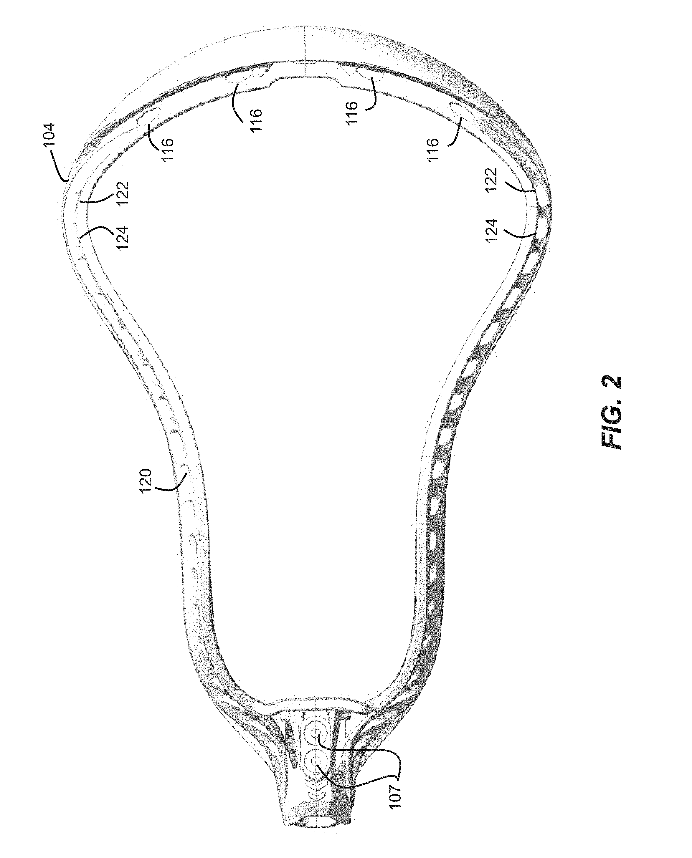
[0010] FIG. 2 is a schematic diagram of a rear view of the lacrosse head of FIG. 1;
[0011] FIG. 3 is a schematic diagram of a right side view of the lacrosse head of FIG. 1, illustrating an upwardly canted forward portion;
[0012] FIGS. 4 and 5 are schematic diagrams of a left side view of the lacrosse head of FIG. 1, which is a mirror opposite of the right side view of FIG. 3;
[0013] FIG. 6 is a schematic diagram of a top view of the lacrosse head of FIG. 1;
[0014] FIG. 7 is a schematic diagram of a bottom view of the lacrosse head of FIG. 1;
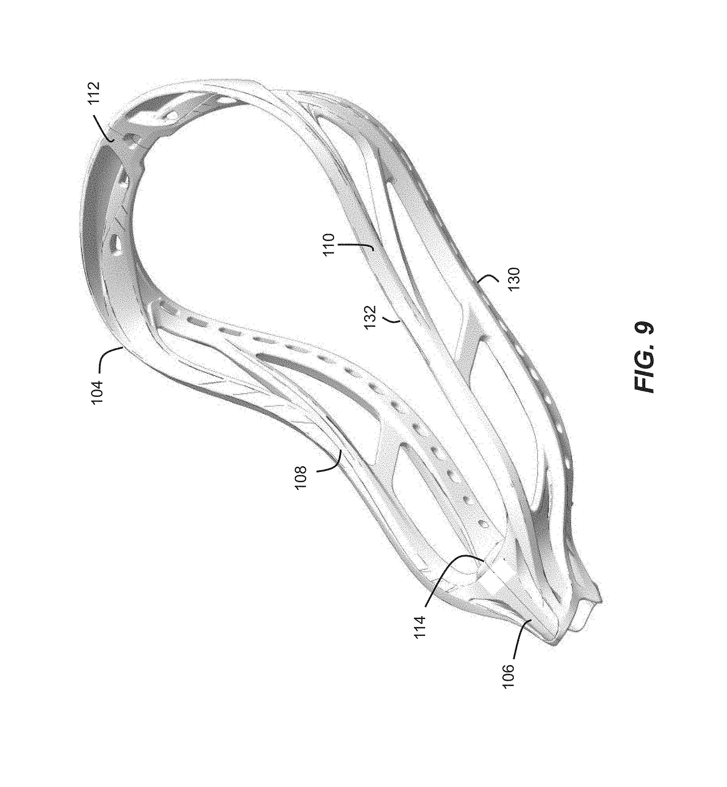
[0015] FIGS. 8 and 9 are schematic diagrams of perspective views of the lacrosse head of FIG. 1;
[0016] FIG. 10 is a schematic diagram of a lacrosse stick handle having a bent end portion, according to an embodiment;
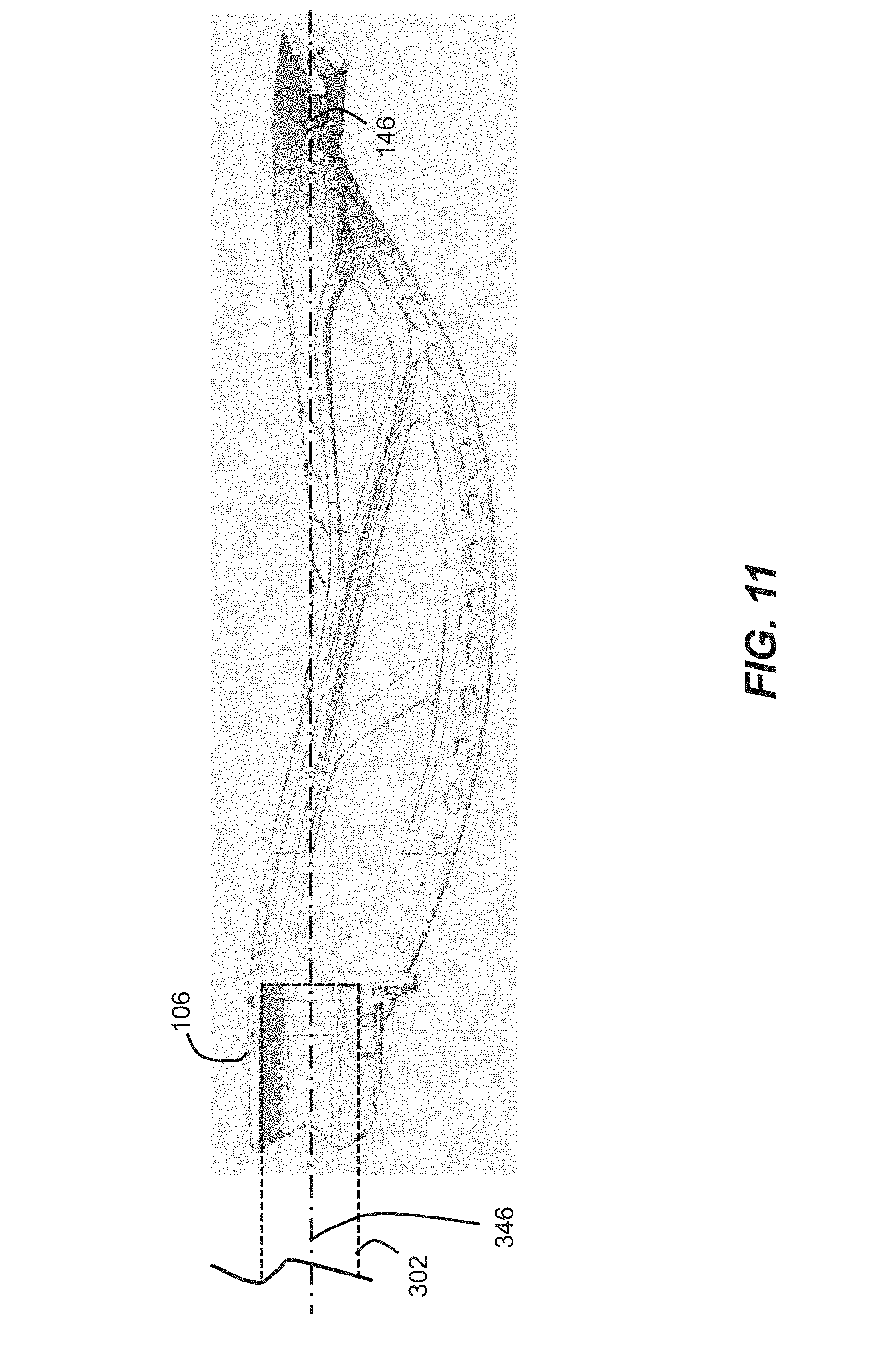
[0017] FIG. 11 is a schematic diagram of a cross-sectional view of an embodiment of a straight head-handle configuration, showing a centerline for purposes of the present embodiments;
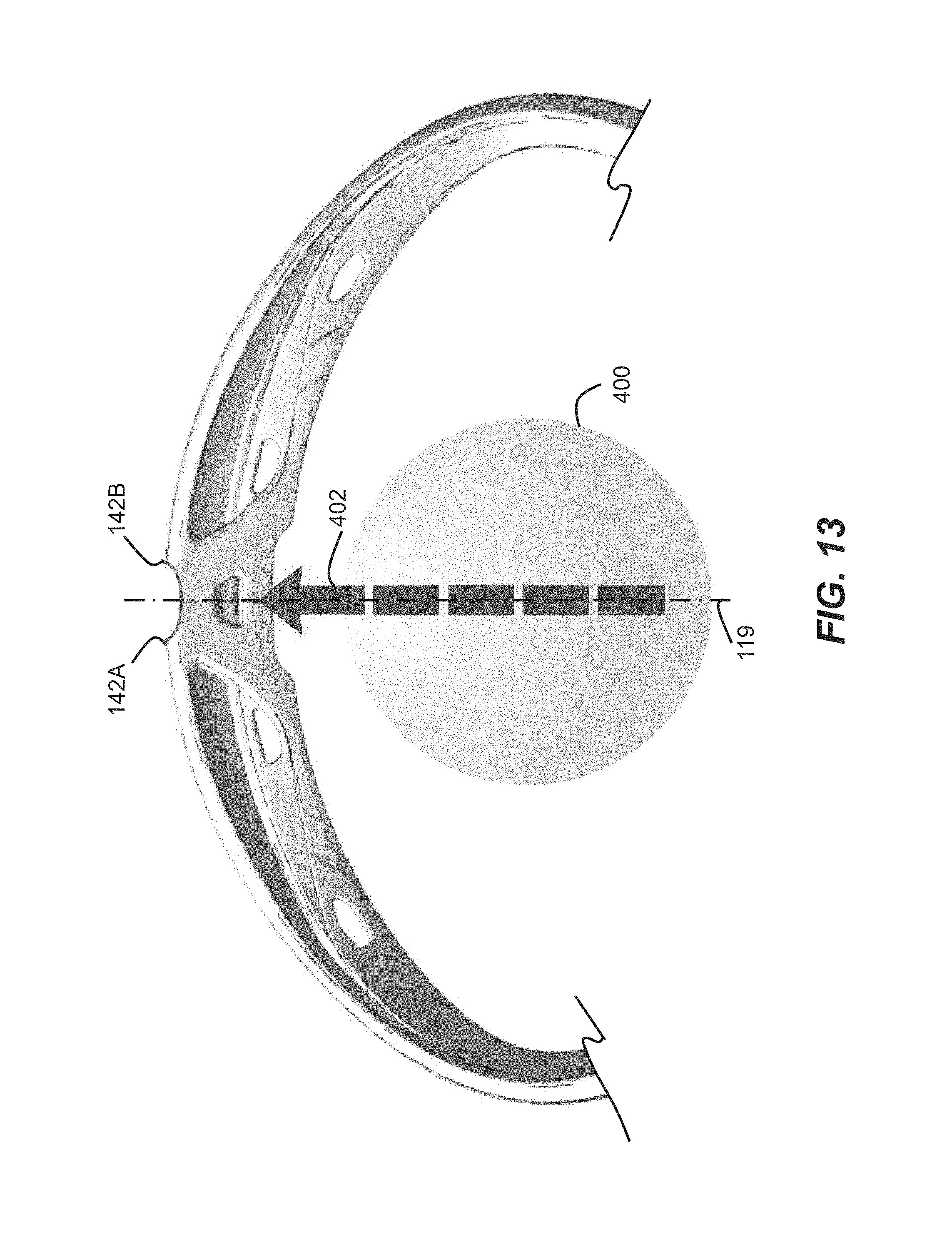
[0018] FIGS. 12 and 13 are schematic diagrams of a partial top view and a partial front view, respectively, of a lacrosse head, showing a transverse wall according to an alternative embodiment;
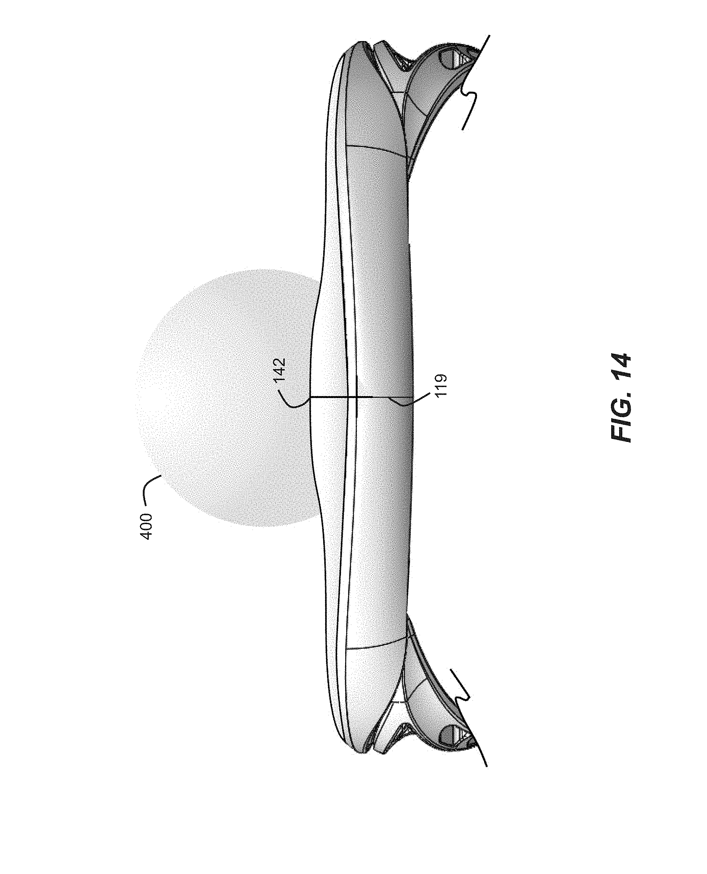
[0019] FIGS. 14 and 15 are schematic diagrams of a partial top view and a partial front view, respectively, of a lacrosse head, showing a transverse wall according to another alternative embodiment; and
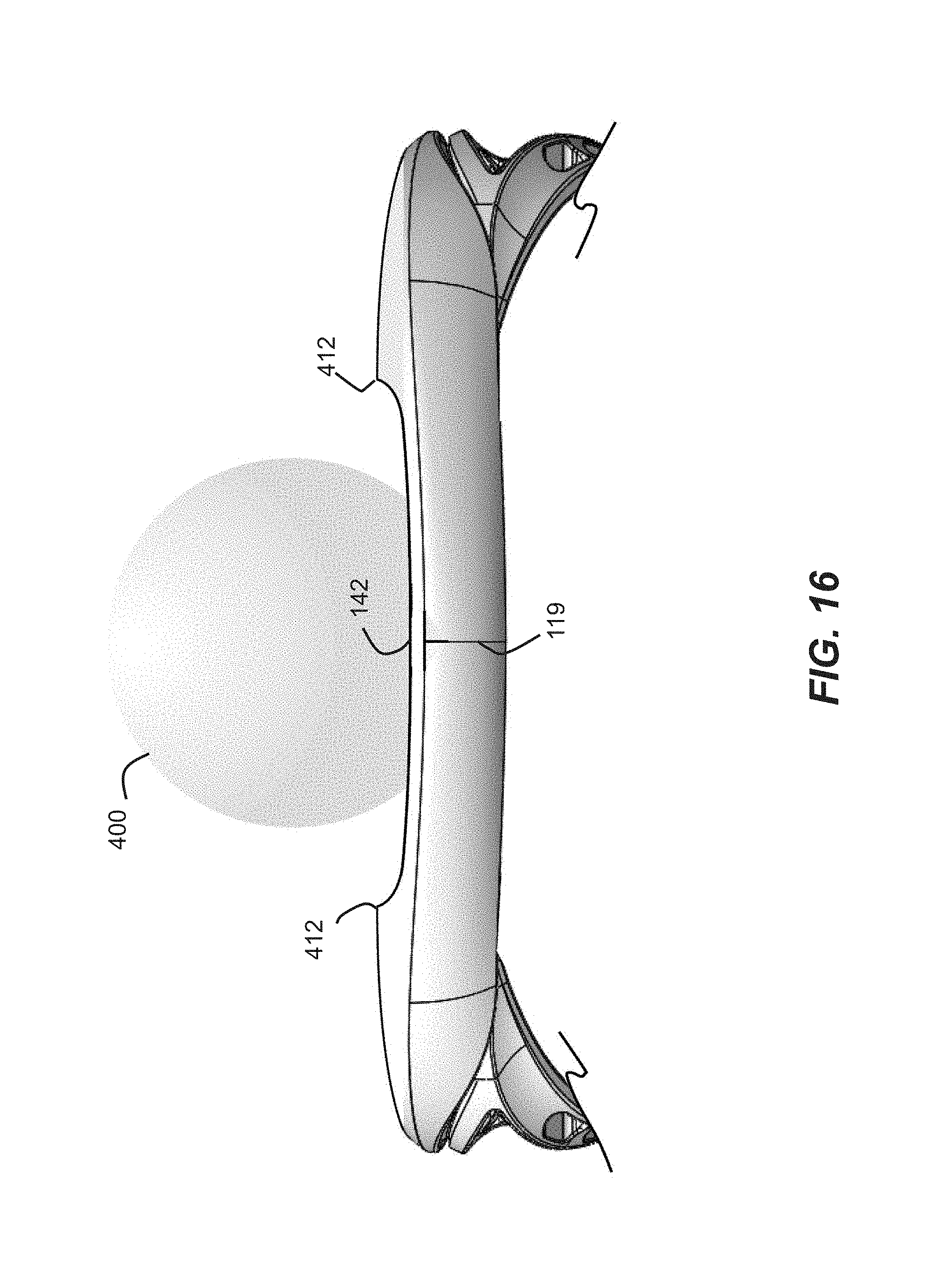
[0020] FIG. 16 is a schematic diagram of a partial top view of a lacrosse head, showing a transverse wall according to another alternative embodiment.
DETAILED DESCRIPTION
[0021] Embodiments provide a lacrosse head having a forward portion that is upwardly canted with respect to a lowest point of a sidewall of the head, which may provide enhanced hold and shot speed. In particular, the lacrosse head may have a lower sidewall rail that descends to a lowest point considerably below a horizontal centerline of the head, and a forward portion that ascends to a highest point significantly spaced higher in a vertical direction from the lowest point of the lower sidewall rail and/or from the horizontal centerline. That significant spacing may enhance the hold of the lacrosse head during maneuvering of a lacrosse stick and especially during shooting, when the lacrosse head may provide a controlled hold on the ball through a swinging motion, which may favorably time the release of the ball to increase shot speed.
[0022] FIGS. 1-9 illustrate an embodiment of a lacrosse stick 100, including a handle 102 shown in dotted lines in FIG. 1 and a double-wall synthetic head 104. As used herein, "stick" refers to the stick as a whole, including the head and the handle. Head 104 may have a generally V-shaped frame having a juncture 106, sidewalls 108 and 110, a transverse wall (or "scoop") 112 joining the sidewalls at their ends opposite juncture 106, and a stop member (or "ball stop") 114 adjoining juncture 106 and joining sidewalls 108 and 110 at their ends nearest juncture 106. The frame may be considered to extend from a rearward end at the juncture 106 to a forward end at the transverse wall 112. As shown, handle 102 may fit into and through juncture 106, may abut stop member 114, and may define (by a majority length of the handle, as discussed below) a horizontal centerline of the handle 102 and head 104 as shown, for example, in the side elevational view of FIG. 3, as well as a bisecting line 119 as shown, for example, in the front view of FIG. 1 (bisecting the head 104 longitudinally into two halves). Screws or other fasteners may be placed through openings 107, securing handle 102 to head 104. Features of lacrosse sticks are shown generally in Tucker et al., U.S. Pat. No. 3,507,495, Crawford et al., U.S. Pat. No. 4,034,984, and Tucker et al., U.S. Pat. No. 5,566,947, which are all incorporated by reference herein.
[0023] In embodiments, lacrosse stick head 104 may have a "traditional" pocket configuration or a "mesh" pocket configuration. The traditional pocket may include thongs made of leather or synthetic material strung from forward thong holes 116 in transverse wall 112 to rearward thong holes 118 in stop member 114. To complete the pocket web, the thongs may have nylon strings threaded around the thongs and string laced through string holes in sidewalls 108 and 110, forming any number of diamonds or other shapes (crosslacing).
[0024] In traditional pockets, thongs (not shown in FIGS. 1-9) made of leather or synthetic material may extend from forward thong holes 116 in transverse wall 112 to rearward thong holes 118 in stop member 114 (see, e.g., FIGS. 6-7). As one embodiment, FIGS. 1, 2, 6, and 7 show four pairs (116, 118) of thong holes that may accept four thongs. Other numbers of pairs may be used. To complete the pocket web, nylon strings may be threaded around the thongs and string may be laced through string holes 120 in sidewalls 108 and 110, forming any number of diamonds or other shapes (crosslacing). In embodiments, one or more throwing or shooting strings may extend transversely between the forward portions of sidewalls 108 and 110, attaching to throwing string holes 124 and a string laced through string holes 122. In embodiments, a thong may not be attached directly to a thong hole, and instead may be connected to a separate material that attaches the thong to the lacrosse head frame and that is easier to adjust through the thong hole. In addition, in some embodiments, a top string (e.g., nylon string) may be strung along the thong holes of the scoop, and the thongs may be attached to the top string.
[0025] A mesh pocket configuration may use a mesh knitted as a continuous piece of material. This continuous piece of material may attach to the lacrosse head as a single unit. The mesh may be attached to the lacrosse head using transverse lacing, which may reinforce the web of the mesh that is adjacent to the lacrosse head.
[0026] Embodiments may include provisions for improving the performance of a men's lacrosse stick, within the context of rules governing the configuration of a men's lacrosse head. In particular, certain rules for men's lacrosse (e.g., NCAA Men's Lacrosse 2017 and 2018 Rules, Rule 1, Sections 18-19) require that the lacrosse head sidewall be no more than 2 inches deep (e.g., in the vertical direction in FIG. 3) and that the lacrosse stick be relatively straight from the butt end to the end of the head, such that when the lacrosse stick is laid flat on a tabletop on the side opposite the netting so that a substantial portion of the lacrosse stick rests on the table, with the butt-end placed off of the table, the distance from the tabletop to the bottom edge of the head at no point exceeds 2-3/4 inches (often referred to as the "tabletop test"). In addition, certain rules for men's lacrosse (e.g., NCAA Men's Lacrosse 2017 and 2018 Rules, Rule 1, Section 17) require that the length of a lacrosse head be a minimum of 10 inches from the outside edge (or distal end) of the head (i.e., scoop tip) to the beginning of the throat of the head (or inside face of the stop member), regardless of whether a ball stop is used. Other rules for men's lacrosse (e.g., NCAA Lacrosse 2017 and 2018 Rules, Appendix IV) specify that a lacrosse ball may measure between 73/4 and 8 inches in circumference, which corresponds to a diameter within a range of 2.47 to 2.55 inches. Within one or more of those restrictions, embodiments provide a favorable relative geometry between a lowest point of a sidewall of the head and a highest point of a forward portion of the head, which enhances hold and control of a ball through a swinging motion, and facilitates higher shot speeds without sacrificing throwing accuracy.
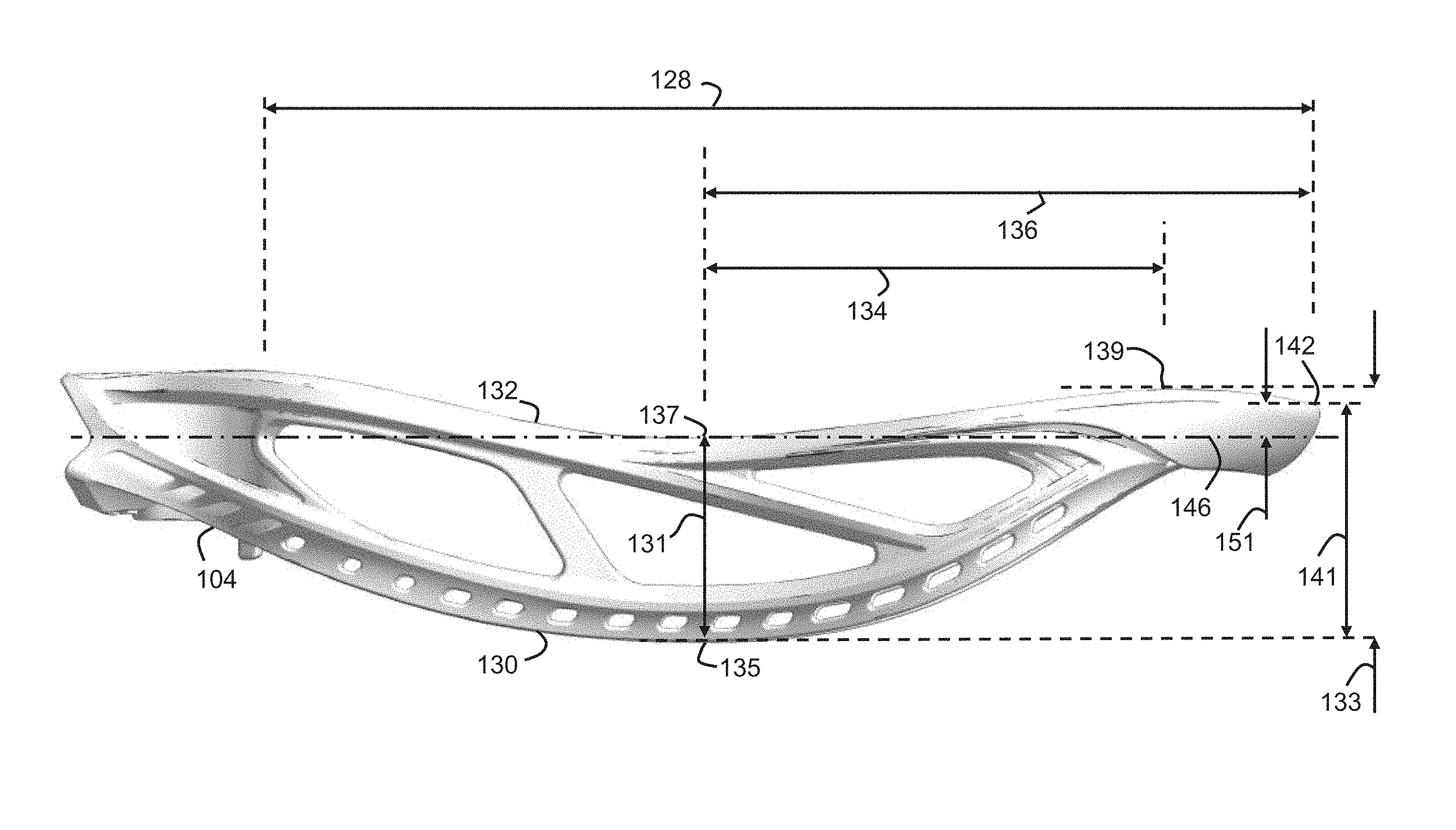
[0027] Referring to the side view of FIG. 3, to provide a beneficial "hold" to a lacrosse head 104, embodiments may incorporate a significant upwardly canted geometry between a lower sidewall rail and a forward portion of a head 104. In embodiments, lacrosse head 104 may have a lower sidewall rail 130 that at its lowest point 135 is a distance 131 below a horizontal centerline 146 of the juncture 106 of the head 104. In embodiments, distance 131 may be, for example, at least about 1.75 inches. In one implementation, as shown in FIG. 3, an upper sidewall rail 132 may descend to a lowest point 137 that is disposed approximately on the horizontal centerline 146 and approximately vertically above the lowest point 135 of the lower sidewall rail 130, with the distance 131 being approximately at the rule-limited 2 inches, e.g., at approximately 1.9 inches below the lowest point 137 of the upper sidewall rail 132 and the horizontal centerline 146. Positioning the lowest point 137 on or below the horizontal centerline 146 may allow embodiments to achieve a maximum downward offset of the sidewalls with respect to the horizontal centerline 146 and a maximum height of the sidewalls, while still complying with the tabletop test.
[0028] In embodiments, the lowest point 135 of the lower sidewall rail 130 and the lowest point 137 of the upper sidewall rail 132 may be disposed at a mid-portion of the head, for example, within a region approximately 1/3 to 2/3 of the distance from the inside (i.e., pocket side) of the stop member 114 to the outside of the transverse wall 112. For example, in one embodiment, the lowest points 135, 137 may be disposed at approximately of the distance from the inside of the stop member 114 to the outside of transverse wall 112. In one particular implementation, with a lacrosse head defining a distance 128 of at least 10 inches (e.g., about 10.1 inches (257 mm)) from the inside face of the stop member 114 to the distal end of the transverse wall 112, the lowest points 135, 137 may be disposed within a region about 3 inches (76 mm) to about 6 inches (152 mm) from the inside of the stop member 114, e.g., with the lowest point 135 at about 4.3 inches (109 mm) from the inside of the stop member 114 and the lowest point 137 at about 4.2 inches (106 mm) from the inside of the stop member 114. In embodiments, distances measured from the inside of a stop member are measured from the stop member itself, as a part of the lacrosse head, and not from any add-on piece (e.g., ball stop or pad) applied to the stop member.
[0029] In alternative embodiments, a lower sidewall rail may extend in the forward direction at a constant maximum distance below the horizontal centerline or may reach the maximum distance at more than one instance, in which case the lowest point may be considered the forwardmost location of the lower sidewall rail at which the maximum distance is reached before ascending toward the highest point of the forward portion of the head. Thus, for example, if there are multiple points at which the lower sidewall rail reaches the maximum distance below the horizontal centerline (e.g., with a wavy lower sidewall rail), then the point that is closest to the highest point of the forward portion of the head may be considered the lowest point.
[0030] Similarly, an upper sidewall rail may extend in the forward direction at a constant lowest elevation or may reach a lowest elevation at more than one instance, in which case the lowest point may be considered the forwardmost location of the upper sidewall rail at which the lowest elevation is reached before ascending toward the highest point of the forward portion of the head. Thus, for example, if there are multiple low points of an upper sidewall rail (e.g., with a wavy upper sidewall rail), then the low point that is closest to the highest point of the forward portion of the head may be considered the lowest point.
[0031] To provide the helpful upwardly canted geometry, embodiments may upwardly cant a forward portion of the head, relative to the lowest point in the sidewalls of the head, which may be in a mid-portion of the head. A forward portion may be considered any portion forward of a point halfway between the inside of the stop member 114 and the distal end of the transverse wall 112 (see, e.g., distance 128 in FIG. 3, which may be at least 10 inches, for example). The upward cant in the forward portion of the head may ascend to a highest point at, for example, any location along the forward end of the sidewalls, the shoulders of the head (at the transitions between the sidewalls and transverse wall), or the transverse wall. For example, as shown in FIG. 3, a forward portion of head 104 may ascend to a highest point 139, which is disposed at a shoulder of the head 104 and is a distance 133 higher in a vertical direction than the lowest point 135 of the lower sidewall rail 130. In one implementation, highest point 139 may be a distance 133 of at least about 2.25 inches higher in a vertical direction than the lowest point 135, e.g., at approximately 2.39 inches in a vertical direction above the lowest point 135, and may be a horizontal distance 134 forward of the lowest point 135 of between about 4 inches to about 5 inches, e.g., at approximately 4.5 inches. In embodiments, horizontal distance 134 may be between about 3 inches to about 6 inches.
[0032] In addition, transverse wall 112 may define a terminal contact point at which a ball traveling in a forward direction generally along bisecting line 119 may last contact and release from the head during a throwing motion of the lacrosse stick. Terminal contact point 142 may be disposed at a highest and/or forwardmost point of lacrosse head 100. Terminal contact point 142 may be disposed at a height even with, or below, the highest point 139, to provide a desired scoop angle that facilitates retrieving ground balls into the head at higher angles of the stick relative to the ground, while also providing a beneficial hold and an optimal release to increase ball velocity during a throw. In embodiments, for example, terminal contact point 142 may be a distance 141 in a vertical direction above the lowest point 135 of at least about 2.25 inches, e.g., about 2.26 inches, and may be a horizontal distance 136 forward of the lowest point 135 of between about 4 inches to about 7 inches, e.g., at approximately 5.84 inches. In addition, in embodiments, the position of the terminal contact point 142 relative to the horizontal centerline 146 may contribute to the beneficial hold and optimal release, with desired performance characteristics obtained at a distance 151 of at least about 5 mm above horizontal centerline 146, for example.
[0033] In embodiments, the terminal contact point 142 may be disposed generally along the bisecting line 119 (see FIG. 1), or may be one or more points each disposed offset from bisecting line 119 (e.g., above and below line 119 in FIG. 1) so long as a ball traveling in a forward direction generally along the bisecting line 119 may last contact and release off of the terminal contact point or points. For example, as shown in the partial top view of FIG. 12 and the partial front view of FIG. 13, terminal contact point 142 may include two points 142A, 142B opposite each other across bisecting line 119 (e.g., to the left and right of line 119 in FIGS. 12 and 13) and equidistant from line 119, and each positioned at a highest elevation and forwardmost position at which a ball 400 may last contact and release from the head in a direction generally along the bisecting line 119 during a throwing motion of the lacrosse stick, as represented by arrow 402.
[0034] In other embodiments, a terminal contact point 142 may not necessarily be both a highest point and a forwardmost point. For example, as shown in the partial top view of FIG. 14 and the partial front view of FIG. 15, terminal contact point 142 may be a highest point (see FIG. 14) but not a forwardmost point in view of the projecting portions 410 of the transverse wall 112 (see FIG. 15). In this configuration, as represented by the arrow 402, a ball 400 moving in a direction generally along the bisecting line 119 may last contact the terminal contact point 142, and not the projecting portions 410, which are beyond the width of the contacting surface of the ball 400. Other embodiments may provide a terminal contact point that is forwardmost, but not highest, such as the configuration shown in FIG. 16, where the terminal contact point 142 is forwardmost but is lower than points 412.
[0035] In embodiments, the transverse wall 112 may define the highest point of a forward portion of a head. For example, referring to the front view of FIG. 1, the transverse wall 112 may define the highest point at two locations equidistant from bisecting line 119, as mirror opposites across line 119. The two locations may be near the shoulder of the head 104, at the transition regions to the sidewalls 108, 110. For example, a transition region between the transverse wall 112 and the upper sidewall rails 132 of the sidewalls 108, 110 may define the highest point. In other embodiments, a highest point of transverse wall 112 may be at a single location disposed approximately on the bisecting line 119 of head 104.
[0036] The geometric relationships between the highest point 139 of the forward portion of the head and the lowest point 135 of the sidewalls of the head, and/or between the terminal contact point 142 of the transverse wall 122 and the lowest point 135 of the sidewalls of the head, may lead to surprising benefits, for example, related to providing a lacrosse stick with optimal hold and control during shooting, affording players increased shot speed, all while complying with applicable rules governing men's lacrosse head construction. Testing of the embodiment shown in FIGS. 1-9 by varyingly-skilled lacrosse players and by a lacrosse swing rig machine, has demonstrated increased shot speed of up to 10% (with a mean increase of about 4-5%), over conventional lacrosse heads. Generally, shot speed may be increased approximately 5 mph. The lacrosse head frame geometry provides an optimized hold of the ball through the throwing motion, while avoiding a prolonged hold that precludes the ball from rolling toward the scoop and causes an uncontrolled downward release of the ball from the pocket, sometimes referred to as "whip." The present embodiments allow a ball to travel farther up the pocket and off the scoop, in a controlled fashion, thereby increasing power on shots and passes.
[0037] As used herein, the "centerline" refers to the centerline of the majority of a handle. In the case of a straight handle, the centerline coincides with the center longitudinal axis of the straight handle. In instances of handles having angled end portions inserted into lacrosse head frames, or in instances of angled throat sections of lacrosse heads, the centerline would be defined by the remaining majority length of the handle that extends away from the angled end portion or angled throat, and that is held by a player. For example, referring to FIG. 10, if a handle 302 bends within the last few inches (e.g., 3 inches) of the end of the handle 302, which in this example is bent at a 10 degree angle, then that bent end portion 303 is to be ignored for purposes of the centerline. Thus, in the example of FIG. 10, the horizontal line 346, which corresponds to the majority length 305 of the handle 302, is the centerline for purposes of the present embodiments. The line 347 is the center longitudinal axis of the bent end portion 303, and is not the centerline for purposes of the present embodiments.
[0038] In embodiments, the increased vertical distance between the lowest point of the sidewall of the head and the highest point of the forward portion of the head, and/or between the lowest point of the sidewall and the terminal contact point, especially when compared to conventional lacrosse head geometries, may allow for an increased slope of the pocket (when viewed from the side) in the forward portion of the head, which may enhance the "hold" of the ball within the pocket, as well as feel, control, and accuracy in handling the ball in the pocket and releasing the ball from the pocket during a throw. For example, as shown in FIG. 4, the upwardly canted geometry may provide an increased angle 143 as graphically represented by the arrow 147 extending between the lowest point 135 of the lower sidewall rail 130 and the terminal contact point 142 of the transverse wall 112. In embodiments, on a head 104 defining a distance 128 of at least 10 inches, angle 143 may be within a range of about 18 degrees to about 30 degrees, and preferably within a range of about 20 degrees to about 25 degrees. In one implementation, angle 143 may be about 21.4 degrees. When a pocket (not shown) is strung to the head, the upwardly canted geometry of the angle 143 may provide an optimal hold on a ball during a throwing motion, to increase shot speed. Due to the optimal hold, a player may start the shooting motion from farther back and still achieve the same release point, and since the player has more time to transfer energy to the ball, the ball may release with a higher velocity. The physics provided by this configuration may be considered similar to the increased energy applied to a golf ball by a wider and/or longer golf club swing. In addition, the upwardly canted geometry, including the increased angle 143 and a more forwardly positioned lowest point 135, may allow deeper portions of a pocket to be positioned more forward in a lacrosse head, which may provide desired hold and control according to player preferences.
[0039] In embodiments, the upwardly canted geometry of the forward portion of the head may be characterized by the relative positions of the lowest point 135 of the lower sidewall rail 130 and the highest point 139 of the forward portion of the head (rather than the terminal contact point 142 of the transverse wall 112). For example, as shown in FIG. 5, the upwardly canted geometry may provide an increased angle 148 as graphically represented by the arrow 149 extending between the lowest point 135 of the lower sidewall rail 130 and the highest point 139. In embodiments, on a head 104 defining a distance 128 of at least 10 inches, angle 148 may be within a range of about 25 degrees to about 30 degrees. In one implementation, angle 148 may be about 28 degrees. When a pocket (not shown) is strung to the head, the upwardly canted geometry of the angle 148 may also provide an optimal hold on a ball during a throwing motion, to increase shot speed. Due to the optimal hold, a player may start the shooting motion from farther back and still achieve the same release point, and since the player has more time to transfer energy to the ball, the ball may release with a higher velocity. Again, the physics provided by this configuration may be considered similar to the increased energy applied to a golf ball by a wider and/or longer golf club swing.
[0040] In further embodiments, the upwardly canted geometry may be characterized by both the angle 143 and the angle 148 together, to provide desired hold and throwing characteristics.
[0041] The lacrosse head embodiments of FIGS. 1-9 are configured to receive a straight handle, and are described herein under the assumption that such a straight handle is received in the lacrosse head. An example of this straight head-handle configuration is shown in the cross-sectional view of FIG. 11, with the horizontal centerline 146 coinciding with the entire centerline 346 of the straight handle 302. In alternative embodiments, a lacrosse head may be configured to receive a bent handle, in which case the same geometric and angular relationships described herein in the context of a straight handle would also apply to the lacrosse head that is configured to receive a bent handle and receives a bent handle. For example, the socket of the juncture 106 could be configured to receive a handle with an end portion bent at an angle of between about 1-10 degrees, with the horizontal centerline 146 corresponding to the centerline of the majority length of the handle. The bent handle configuration may provide the same benefits as a straight head-handle configuration, for example, in terms of the upward cant of the forward portion of the head with respect to the lowest point of the sidewalls of the head, which facilitates optimized hold and increased shot speed. Thus, in embodiments, a lacrosse stick having the features described herein may include configurations having a downwardly canted handle, examples of which are described in U.S. Pat. No. 7,488,266, issued Feb. 10, 2009, which is herein incorporated by reference in its entirety.
[0042] Examples of suitable materials for a lacrosse head according to the present embodiments include nylon, composite materials, elastomers, metal, urethane, polycarbonate, polyethylene, polypropylene, polyketone, polybutylene terephalate, acetals (e.g., Delrin.TM. by DuPont), acrylonitrile-butadiene-styrene (ABS), acrylic, acrylic-styrene-acrylonitrile (ASA), alcryn (partially crosslinked halogenated polyolefin alloy), styrene-butadiene-styrene, styrene-ethylene-butylene styrene, thermoplastic olefinic (TPO), thermoplastic vulcanizate (TPV), ethylene-propylene rubber (EPDM), and polyvinyl chloride (PVC). Examples of suitable materials for a handle according to the present embodiments include wood, metal (e.g., aluminum, titanium, scandium, CU31, C405, and C555), plastic, and composites.
[0043] For purposes of convenience various directional adjectives are used in describing the embodiments. For example, the description may refer to the top, bottom, and side portions or surfaces of a component. It may be appreciated that these are only intended to be relative terms and, for example, the top and bottom portions may not always be aligned with vertical up and down directions depending on the orientation of a component or lacrosse stick.
[0044] It should also be noted that relative terms such as "upper," "lower," "top," and "bottom," are used herein to describe the embodiments as depicted in the accompanying figures and are not intended to be limiting. Unless the context of the usage dictates otherwise, when used in reference to a lacrosse stick or head as a whole, the term "front" refers to the side of the lacrosse stick through which a ball is caught and the terms "back" and "rear" refer to the side of the lacrosse stick that is opposite to the "front" and is where the pocket is disposed. It should also be noted that figures provided herein generally depict the illustrated lacrosse head with the pocket side of the head (i.e., the rear) facing downward. It will be apparent to skilled practitioners that the orientation of a lacrosse stick varies dramatically during play and the relative positions of the elements of the present embodiments will similarly vary from those depicted.
[0045] The foregoing disclosure of the preferred embodiments has been presented for purposes of illustration and description. It is not intended to be exhaustive or to limit the embodiments to the precise forms disclosed. Many variations and modifications of the embodiments described herein will be apparent to one of ordinary skill in the art in light of the above disclosure.
[0046] While various embodiments have been described, the description is intended to be exemplary, rather than limiting, and it will be apparent to those of ordinary skill in the art that many more embodiments and implementations are possible that are within the scope of the embodiments. Any feature of any embodiment may be used in combination with or substituted for any other feature or element in any other embodiment unless specifically restricted. Accordingly, the embodiments are not to be restricted except in light of the attached claims and their equivalents. Also, various modifications and changes may be made within the scope of the attached claims.
[0047] Further, in describing representative embodiments, the specification may have presented a method and/or process as a particular sequence of steps. However, to the extent that the method or process does not rely on the particular order of steps set forth herein, the method or process should not be limited to the particular sequence of steps described. As one of ordinary skill in the art would appreciate, other sequences of steps may be possible. Therefore, the particular order of the steps set forth in the specification should not be construed as limitations on the claims. In addition, the claims directed to the method and/or process should not be limited to the performance of their steps in the order written, and one skilled in the art can readily appreciate that the sequences may be varied and still remain within the spirit and scope of the present embodiments.
* * * * *
D00000
D00001
D00002
D00003
D00004
D00005
D00006
D00007
D00008
D00009
D00010
D00011
D00012

D00013
D00014
D00015

D00016
XML
uspto.report is an independent third-party trademark research tool that is not affiliated, endorsed, or sponsored by the United States Patent and Trademark Office (USPTO) or any other governmental organization. The information provided by uspto.report is based on publicly available data at the time of writing and is intended for informational purposes only.
While we strive to provide accurate and up-to-date information, we do not guarantee the accuracy, completeness, reliability, or suitability of the information displayed on this site. The use of this site is at your own risk. Any reliance you place on such information is therefore strictly at your own risk.
All official trademark data, including owner information, should be verified by visiting the official USPTO website at www.uspto.gov. This site is not intended to replace professional legal advice and should not be used as a substitute for consulting with a legal professional who is knowledgeable about trademark law.