Adjustable And Removable Canopy For A Lounge Or Chair
Autore; Gregory J. ; et al.
U.S. patent application number 16/059749 was filed with the patent office on 2019-02-14 for adjustable and removable canopy for a lounge or chair. This patent application is currently assigned to Aqua-Leisure Industries, Inc.. The applicant listed for this patent is Aqua-Leisure Industries, Inc.. Invention is credited to Gregory J. Autore, Scott R. de Grasse.
| Application Number | 20190045935 16/059749 |
| Document ID | / |
| Family ID | 65274395 |
| Filed Date | 2019-02-14 |


| United States Patent Application | 20190045935 |
| Kind Code | A1 |
| Autore; Gregory J. ; et al. | February 14, 2019 |
ADJUSTABLE AND REMOVABLE CANOPY FOR A LOUNGE OR CHAIR
Abstract
An adjustable and removable canopy may be affixed to a chair, lounge, recliner, or the like. The canopy comprises two flexible, aligned rods having a fabric panel extending between them. The rods attached to the lounge or chair so as to form an arc across and over the user of the lounge or chair. Adjustment straps extend from the rods to the lounge or chair. A plurality of connectors located on the adjustment straps allow the shortening or lengthening of the straps so that the position of the canopy relative to the user may be selectively adjusted.
| Inventors: | Autore; Gregory J.; (Spring Valley, OH) ; de Grasse; Scott R.; (Marshfield, MA) | ||||||||||
| Applicant: |
|
||||||||||
|---|---|---|---|---|---|---|---|---|---|---|---|
| Assignee: | Aqua-Leisure Industries,
Inc. Avon MA |
||||||||||
| Family ID: | 65274395 | ||||||||||
| Appl. No.: | 16/059749 | ||||||||||
| Filed: | August 9, 2018 |
Related U.S. Patent Documents
| Application Number | Filing Date | Patent Number | ||
|---|---|---|---|---|
| 62542867 | Aug 9, 2017 | |||
| Current U.S. Class: | 1/1 |
| Current CPC Class: | A47C 7/66 20130101; A47C 15/006 20130101; A47C 1/14 20130101; A47C 1/143 20130101 |
| International Class: | A47C 7/66 20060101 A47C007/66; A47C 1/14 20060101 A47C001/14; A47C 15/00 20060101 A47C015/00 |
Claims
1. A canopy for a lounge or chair comprising: a pair of spaced apart, aligned, flexible rods; a panel of material attached to each of the rods and extending therebetween along substantially the entire length of the rods; first attachment means for attaching each of the rods to the lounge or chair at each end of the rod to form an arc over the lounge or chair; a first adjustment strap connected to and extending from a location adjacent a first one of the rods for attachment to the lounge or chair; a second adjustment strap connected to and extending from a location adjacent to the second one of the rods for attachment to the lounge or chair; second attachment means for securing an end of each strap to the lounge or chair. said first and second adjustment straps being configured to allow the selective adjustment of the position of canopy relative to the lounge or chair by adjusting the length of the strap connecting the canopy to the lounge or chair.
2. The canopy of claim 1, wherein the panel material and the adjustment straps are removably attached to the lounge or chair.
3. The canopy of claim 2, wherein said second attachment means comprises a loop of material extending from the lounge or chair.
4. The canopy of claim 3, wherein the adjustment strap comprises means to selectively shorten or increase the length of the strap between the canopy and the lounge or chair so as to permit the selection of the position of the canopy.
Description
RELATED APPLICATION
[0001] This application claims priority under 35 U.S.C. Section 119(e) to U.S. Provisional Application Ser. No. 62/542,867 entitled "ADJUSTABLE AND REMOVABLE CANOPY," filed on Aug. 9, 2017, which is hereby incorporated by reference in its entirety for all purposes.
FIELD OF THE INVENTION
[0002] This invention relates to canopies for providing shade to a person sitting or reclining on a lounge or chair, and particularly to canopies that are adjustable and removable from the lounge or chair.
SUMMARY OF THE INVENTION
[0003] While many individuals enjoy sunbathing or sunning while sitting in a chair or lying on a lounge or recliner, they often desire to have some shade, at least over the face and neck or the upper part of the body. Sometimes a person wants to read a book without the annoyance of glare from the sun, or simply desires to avoid the direct rays of the sun for health reasons.
[0004] The instant invention provides a canopy or shade that may be readily attached to and removed from a chair, lounge, recliner, or the like. The position of the canopy relative to the user may be easily adjusted to provide the desired protection from the sun. If the user desires full sun, the canopy may readily be removed.
DESCRIPTION OF THE DRAWINGS
[0005] Non-limiting embodiments of the present invention will be described by way of example with reference to the accompanying figures, which are schematic and are not intended to be drawn to scale. In the figures, each identical or nearly identical component illustrated is typically represented by a single numeral. For purposes of clarity, not every component is labeled in every figure, nor is every component of each embodiment of the invention shown where illustration is not necessary to allow those of ordinary skill in the art to understand the invention. In the figures:
[0006] FIG. 1 is a perspective view of a canopy according to the instant invention, attached to a floating lounge.
[0007] FIG. 2 depicts the canopy removed from the lounge and in a flattened position.
[0008] FIG. 3 is an illustration of the canopy adjusted to three different positions.
[0009] FIG. 4 depicts an adjustment strap attached to the side of the lounge and to the canopy, and the two rods attached to the same side of the lounge.
[0010] FIG. 5 is a close-up view of the adjustment strap extending from the front of the canopy to the side of the lounge.
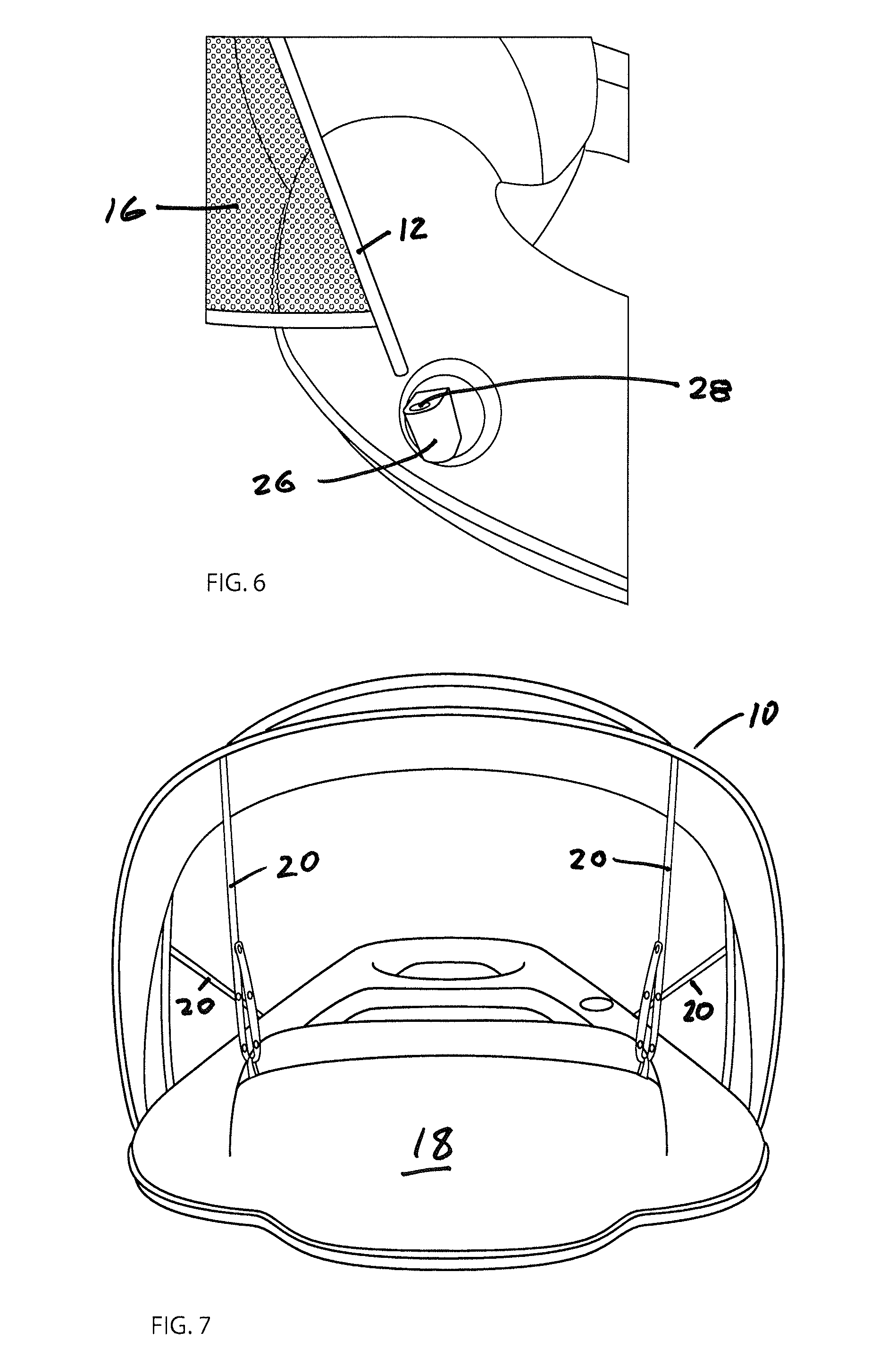
[0011] FIG. 6 is a close-up view of the attachment mechanism affixed to the lounge for receiving the end of one of the rods forming the canopy.
[0012] FIG. 7 is a view of the canopy from the head of the lounge, showing the adjustment straps attached at one end to the lounge and at the other end to the canopy.
DETAILED DESCRIPTION OF THE INVENTION
[0013] As shown in FIG. 1, in one aspect, the canopy 10 of the instant invention is comprised of two fiberglass or plastic rods 12 and 14 that are spaced apart, with a fabric panel 16 attached and extending between the rods to form a canopy. The rods are removably attachable to the lounge 18 and are of such a length that, when so attached, they bend to form a curved or arced canopy over the user. In one aspect of the invention, adjustment straps 20 are affixed to the front and rear of the canopy and are removably attachable to the lounge (see FIGS. 3 and 4) to allow positioning and securement of the canopy at the desired angle relative to the sun, as explained more fully below.
[0014] FIG. 2 depicts the canopy removed from the lounge. As previously stated, fabric panel 16 extends between rods 12 and 14. Adjustment straps 20 are attached to and extend from the canopy. The fabric panel may be comprised of sections of different materials: for example, it may include a section of mesh material 16A at each end with opaque fabric material 16B comprising the remainder.
[0015] FIG. 3 illustrates three possible positions for the canopy 10 in this particular aspect of the invention. Each of two adjustment straps 20 is affixed to or secured on the front edge of the canopy 10 and may be removably attached to each side of the lounge 18 as described below. Each of two adjustment straps 20 affixed to the rear edge of the canopy may similarly be removably attached to the lounge. (See FIG. 7). It will be recognized that other known attachment means, such as clips, buttons, or hook-and-loop fasteners, may be employed to attach the adjustment straps to the lounge Likewise, although the adjustment straps 20 are here shown as affixed to the canopy as by sewing, they could be removably attached to the canopy by various attachment means, such as clips, buttons, or hook-and-loop fasteners.
[0016] FIG. 4 depicts one of the adjustment straps 20 extending from the front of the canopy 10 to a side of the lounge. In this embodiment, the strap 20 may be connected via a fabric loop 22 extending from the lounge, As shown in FIG.5, strap 20 has two sets of snap connectors 24 along its length: on one side, three male connectors and on the other, three female connectors. After threading the end of strap 20 though loop 22, one may adjust the span of strap 20 (between the canopy and the lounge) by selecting the appropriate opposed connectors to snap together.
[0017] By shortening or lengthening the span of the adjustment straps 20, the position and angle of the canopy relative to the user may be selectively altered. In this particular aspect of the invention, three possible positions are illustrated in FIG. 3, but more or fewer positions could be accommodated by including the desired number of connecting paired snap connectors on the front and rear adjustment straps.
[0018] FIG. 6 shows the end of one of the rods 12 or 14 positioned for receipt by a connector 26 welded to lounge 18. Connector 26 includes a slot or aperture 28 into which the end of the rod may be inserted. The outward tension on the rods 12 and 14, once inserted in connectors 26 will serve to maintain the ends of the rods within the connectors until such time as removal of the canopy is desired. Of course, the rods could be removably attached to the canopy by various other attachment means, such as clips, loops, or hook-and-loop fasteners.
[0019] Finally, FIG. 7 depicts canopy 10 as seen from the headrest end of the lounge 18. Adjustment straps 20 removably and adjustably attach canopy 10 to the lounge using the same loop and snap arrangement as described above.
[0020] Although the instant invention has been described and illustrated herein as applied to a lounge, it is equally applicable to a chair, a recliner, and like devices. Those of ordinary skill in the art will readily comprehend how to attach the canopy to the arms and back of a chair, or the sides and headrest end of a recliner, in accordance with the instant invention.
[0021] A variety of other means and/or structures for performing the functions and/or obtaining the results and/or one of more of the advantages described herein, and each of such variations and/or modifications is deemed to be within the scope of the present invention. More generally, those skilled in the art will readily appreciate that all parameters, dimensions, materials, and configurations described herein are meant to be exemplary and the actual parameters, dimensions, materials and/or configurations will depend upon the specific application or applications for which the teachings of the present invention is/are used.
[0022] Those skilled in the art will recognize or be able to ascertain, using no more than routine experimentation, many equivalents to the specific embodiments of the invention described herein. It is therefore to be understood that the foregoing embodiments are presented by way of example only and that, with the scope of the appended claims and equivalents thereto, the invention may be practiced otherwise than as specifically described and claimed. The present invention is directed to each individual feature, system, article, material, and/or method described herein. In addition, any combination of two or more such features, systems, articles, materials, and/or methods, if such features, systems, articles, materials, and/or methods are not mutually inconsistent, is included within the scope of the present invention.
* * * * *
D00000
D00001
D00002
D00003
D00004
XML
uspto.report is an independent third-party trademark research tool that is not affiliated, endorsed, or sponsored by the United States Patent and Trademark Office (USPTO) or any other governmental organization. The information provided by uspto.report is based on publicly available data at the time of writing and is intended for informational purposes only.
While we strive to provide accurate and up-to-date information, we do not guarantee the accuracy, completeness, reliability, or suitability of the information displayed on this site. The use of this site is at your own risk. Any reliance you place on such information is therefore strictly at your own risk.
All official trademark data, including owner information, should be verified by visiting the official USPTO website at www.uspto.gov. This site is not intended to replace professional legal advice and should not be used as a substitute for consulting with a legal professional who is knowledgeable about trademark law.