Hair Styling Device for Curling or Waving Hair and Method for Operating Such a Hair-Styling Device
Kock; Marwin
U.S. patent application number 16/073978 was filed with the patent office on 2019-02-14 for hair styling device for curling or waving hair and method for operating such a hair-styling device. The applicant listed for this patent is WIK Far East Ltd.. Invention is credited to Marwin Kock.
| Application Number | 20190045901 16/073978 |
| Document ID | / |
| Family ID | 55753394 |
| Filed Date | 2019-02-14 |


| United States Patent Application | 20190045901 |
| Kind Code | A1 |
| Kock; Marwin | February 14, 2019 |
Hair Styling Device for Curling or Waving Hair and Method for Operating Such a Hair-Styling Device
Abstract
A hair-styling device serves to curl or wave hair. Said hair-styling device comprises two styling bodies 5, 5.1, which interact with each other to style the hair and can be rotated about the longitudinal axis of the styling bodies and of which at least one of the styling bodies 5, 5.1 is driven, which styling bodies 5, 5.1 have a shell surface contoured by elevations and recesses and are arranged in relation to each other in such a way that complementary contours of the two styling bodies 5, 5.1 mesh in the course of rotation of the two styling bodies. The styling bodies 5, 5.1 have a bone-shaped cross-sectional geometry having two head sections 7, 7.1 designed with a shell surface 8 that is convexly rounded at least in some sections and having a tapered central section 6 located between the head sections and designed with a concave shell surface. The radius of curvature in the region of the central apex 9 of the head sections 7, 7.1 of the one styling body 5, 5.1, 5.2 corresponds to the radius of curvature of the tapered central section 6 of the other styling body. The axis of rotation 11, 11.1 of the styling bodies (5, 5.1) is arranged in the central section 6 centrally between the central apexes 9 of the head sections 7, 7.1.
| Inventors: | Kock; Marwin; (Essen, DE) | ||||||||||
| Applicant: |
|
||||||||||
|---|---|---|---|---|---|---|---|---|---|---|---|
| Family ID: | 55753394 | ||||||||||
| Appl. No.: | 16/073978 | ||||||||||
| Filed: | March 8, 2017 | ||||||||||
| PCT Filed: | March 8, 2017 | ||||||||||
| PCT NO: | PCT/EP2017/055467 | ||||||||||
| 371 Date: | July 30, 2018 |
| Current U.S. Class: | 1/1 |
| Current CPC Class: | A45D 1/14 20130101; A45D 1/08 20130101; A45D 1/12 20130101; A45D 2/40 20130101; A45D 1/06 20130101; A45D 1/04 20130101 |
| International Class: | A45D 1/06 20060101 A45D001/06; A45D 2/40 20060101 A45D002/40 |
Foreign Application Data
| Date | Code | Application Number |
|---|---|---|
| Mar 17, 2016 | DE | 20 2016 101 485.9 |
| Aug 31, 2016 | DE | 20 2016 005 287.0 |
Claims
1-16. (canceled)
17. A hair-styling device for curling or waving hair, comprising: two styling bodies, which interact with each other to style the hair, which may be rotated about their longitudinal axis and of which at least one of the styling bodies is driven, which styling bodies have a shell surface contoured by elevations and recesses and are arranged in relation to each other in such a way that complementary contours of the two styling bodies mesh in the course of rotation of the two styling bodies, wherein the styling bodies have a bone-shaped cross-sectional geometry having two head sections designed with a shell surface that is convexly rounded in one or more sections and having a tapered central section located between the head sections and designed with a concave shell surface, wherein the radius of curvature in the region of the central apex of the head sections of the one styling body corresponds to the radius of curvature of the tapered central section of the other styling body, and that the axis of rotation of the styling bodies is arranged in the central section centrally between the central apexes of the head sections.
18. The hair-styling device of claim 17, wherein the thickened head sections have a width, said width corresponds to a multiple of the width of the central section.
19. The hair-styling device of claim 17, wherein the head sections of the styling bodies in an area of their central apexes have a larger radius of curvature than in an area of their side apexes.
20. The hair-styling device of claim 18, wherein the head sections of the styling bodies in the area of their central apexes have a larger radius of curvature than in an area of their side apexes.
21. The hair-styling device of claim 17, wherein the styling bodies carry a hair contact functional part in their head sections in the area of the apexes of an transition from the convexly rounded shell surface to the concave shell surface of the central section.
22. The hair-styling device of claim 21, wherein the hair contact functional part is a hair entrainer which is adapted according to its material properties.
23. The hair-styling device of claim 21, wherein the hair contact functional part is a care substance applicator.
24. The hair-styling device of claim 22, wherein the hair contact functional part is a care substance applicator.
25. The hair-styling device of claim 17, wherein both styling bodies have the same cross-sectional geometry and an same cross-sectional size.
26. The hair-styling device of claim 17, wherein the styling bodies when rotating about their axis of rotation may be moved past each other, without any mutual contact.
27. The hair-styling device of claim 17, wherein both styling bodies, in order to be rotatably driven, are connected to a gear which is driven by a common motor.
28. The hair-styling device of claim 17, wherein the hair styling device has arms, wherein each arm carries on its side directed towards the other arm a styling body, and wherein said arms are pivotally connected to each other to open and close the hair-styling device for inserting a hair strand.
29. The hair-styling device of claim 17, wherein the styling bodies are made of a heat conducting material, such as an aluminum alloy, and wherein an electric heating element is disposed above the surface of their head sections.
30. The hair-styling device of claim 17, wherein the styling bodies are made of a thermally conductive material, such as an aluminum alloy, and wherein each part housing the styling bodies has one or more radiating heat source.
31. A method for operating the hair styling device of claim 17, wherein the styling bodies are driven according to a predetermined program with reference to their drive, and wherein a control program privileges a non-constant drive of the styling bodies.
32. The method of claim 31, wherein the styling bodies are driven with an alternating slow and faster driving speed.
33. The method of claim 32, wherein the styling bodies are driven intermittently.
34. The method of claim 33, wherein the intermittent driving of the styling bodies is cycled according to 90.degree.-positions of the styling bodies to each other and a drive interruption is performed in one or more of said 90.degree.-positions.
Description
BACKGROUND
[0001] The present disclosure refers to a hair-styling device for curling or waving hair, comprising two styling bodies, which interact with each other to style the hair and may be rotated about the longitudinal axis of the styling bodies and of which at least one of the styling bodies is driven, wherein said styling bodies have a shell surface contoured by elevations and recesses and are arranged in relation to each other in such a way that complementary contours of the two styling bodies mesh in the course of rotation of the two styling bodies. A method for operating such a hair-styling device is also described.
[0002] Different hair styling devices are used to curl or wave hair, depending on the desired hair styling result to be obtained. Crimpers are, for example, known for curling hair. These devices are provided with two arms, which are pivotally connected to each other. Thus, such hair styling devices may be opened and closed in a pincer-like manner. The opening and closing of the arms are used for receiving and releasing a strand of hair to be styled. Each arm of such hair styling devices carries at its side, directed towards the other arm, a styling body. At least one, but typically both, of the styling bodies are heated, like a resistor heater, PCT-heater, or something similar. In the case of a crimper, a heated contact plate with a wavy or zig-zag-shaped contour on its surface facing the hair to be styled is provided. The hair styling surface of such a plate-like styling body is characterized by elevations and recesses. The styling bodies of both arms are arranged to each other in such a way that the elevations of the one styling body engage in the recesses of the other styling body. A strand of hair which is positioned into the opened hair styling device between the styling bodies is obtained by pressing the arms and simultaneous thermal action on the hair held between the styling bodies. For the styling process of the hair it is required that the hair be held for a certain time between the styling plates. The styling of a hair strand occurs with such a device at discrete steps, since in a styling step only a portion of a hair strand may be styled, i.e. the one corresponding to the width of the plate-like styling bodies.
[0003] A development of such a hair styling device is known from EP 2 366 306 A1. The hair styling device disclosed by this reference is also used for forming curls using crimpers. In this hair styling device, the styling bodies are each rotatably supported within an arm of the hair styling device and have a cross-sectional geometry like a gear or gear crown. In this hair styling device, the teeth of the styling body form the elevations and the tooth interspaces form the recesses. Both styling bodies are engaged like how two gears would engage with their respective contours. The styling bodies must be driven in opposite rotational directions to perform the hair styling. An advantage of such a hair styling device utilizing crimpers, as previously described, is that the hair in the hair styling gap between the styling bodies is automatically drawn in when rotating the same. Thus, a hair strand to be styled may be curled along its entire length, without requiring multiple applications of the hair styling device.
[0004] However, due to the crown-gear-like cross-sectional geometry of the styling bodies and their mutual engagement, such a hair styling device is only suitable for forming relatively small curls. Thus, such hair styling devices must be compared to a crimper, with respect to the styling results.
[0005] In the above-mentioned hair styling devices, manipulation of the hair is only possible with both hands. While one hand holds the hair styling device, the other hand must supply the hair strand to be styled on the device or introduce the strand therein. To curl, the hair styling device must also be rotated about its longitudinal axis.
[0006] EP 2 651 260 B discloses a hair styling device in which a hair strand to be curled is automatically drawn into a hair styling chamber of the device. The device contains a hair styling shaft, around which the drawn hair is wound. After the hair styling, the hair strand is released. This hair styling device curls a hair strand similar to a conventional curler, but instead the hair strands are automatically wound through the device in the hair styling chamber around the hair styling shaft. A drawback of such a device is that a user is not able to see what is happening to the hair within the closed hair styling chamber. A user is thus unable to rapidly intervene where an impeding knot forms within the hair strands. Moreover, this device is only suitable for curling long hairs and for providing relatively small curls.
[0007] The foregoing examples of the related art and limitations therewith are intended to be illustrative and not exclusive. Other limitations of the related art will become apparent to those of skill in the art upon a reading of the specification and a study of the drawings.
SUMMARY
[0008] Proceeding from the foregoing, an aspect of the present disclosure is to provide a hair styling device, in which a hair strand may be curled or even waved over its entire length, without the need for multiple applications of the hair styling device, wherein the focus is on the styling of large curls or waves, such as so-called beach waves. The following embodiments and aspects thereof are described and illustrated in conjunction with systems, tool and methods which are meant to be exemplary and illustrative, not limiting in scope. In various embodiments, one or more of the above described problems have been reduced or eliminated, while other embodiments are directed to other improvements.
[0009] This is achieved through the present disclosure by the hair styling device of the type indicated, wherein the styling bodies have a bone-shaped cross-sectional geometry having two head sections designed with a shell surface that is convexly rounded at least in some sections and having a tapered central section located between the head sections and designed with a concave shell surface, wherein the radius of curvature in the region of the central apex of the head sections of the one styling body corresponds to the radius of curvature of the tapered central section of the other styling body, and that the axis of rotation of the styling bodies is arranged in the central section centrally between the central apexes of the head sections.
[0010] In this hair styling device, the styling bodies are rotatably supported and have a bone-shaped cross-sectional geometry. The styling bodies extend over a certain axial length. Therebetween, a hair styling gap is formed, through which a hair strand to be styled is moved. The bone-shaped cross-sectional geometry is provided by a cross-sectional shaping of the styling bodies, of which, are provided with thicker width-wise head sections and tapered central sections disposed between the head sections. Such a styling body has a tapered cross-sectional geometry through the central section. The head sections have a convex rounded shell surface. The central section connecting both head sections, on the other hand, has a concave curvature at both of its opposed side surfaces. The structures forming the central section may also have a cross-sectional geometry with an inverted elliptical shape. Therefore, providing tapering within the styling body. The radius of curvature in the central apex area of the head sections of one of the styling bodies and the radius of curvature of the tapered central section of the other styling body are adapted to each other for engagement of the styling bodies for hair styling. The axis of rotation of the respective styling body is in the central section, particularly, between the terminal central apexes of the head sections. The styling bodies are moved in opposed direction, for hair styling, wherein at least one of the styling bodies is driven. The styling bodies are positioned with respect to each other so that during their rotational movement, the head section of one styling body penetrates the concave tapering of the head section of the other styling body until its central apex is facing the apex of the tapering of the central section and is then extracted from the engagement position in the tapering again. During further rotational movement, this head section is again extracted from the tapering previously housing the head section and a head section of the other styling body is then introduced into the tapering formed by the central section of the styling body, whose head section was previously introduced in the tapering of the other styling body.
[0011] In this concept, due to the particular cross-sectional geometry of both styling bodies, due to the rotation of the styling bodies while rotating the same with an opposed driving direction, the width of the hair styling gap between the styling bodies changes cyclically. The width of the hair styling gap, in which the hair to be styled or the hair strand to be styled is received, is smallest, when the central apex of the head section of the one styling body faces the apex of the tapering of the other styling body. This position is achieved every 90.degree.. In this position, if desired, a contact between both styling bodies may be foreseen. However, an embodiment is disclosed, wherein the position of both styling bodies pass each other without contacting. The remaining gap between the shell surface of one styling body and the shell surface of the other styling body is typically between 0.5 mm and 2 mm. The cyclical change of the gap width of the hair styling gap facilitates a delicate styling of a hair strand, without exerting excessive traction on the same, if applicable. In a further embodiment, the gap width may be set by changing the distance of the rotational axis of both styling bodies to each other. A remaining hair styling gap having a larger gap width may also be reasonable while styling thick hair, whereas for styling thinner hair a smaller gap width is desired.
[0012] As in conventional hair styling devices of this type, the styling bodies of the present disclosure are heated around at least their head sections. Since the styling bodies are typically made of heat conductive material, such as an aluminum alloy, the heating of such styling bodies around their head sections is considered to be sufficient. Moreover, the central section is also heated due to heat conduction. The styling bodies may also be heated from the side opposite of the hair styling gap by means of radiation heating. It is also possible to supply a flow of warm air for heating, which exits the hair styling device through the styling bodies and the hair styling gap.
[0013] In such a hair styling device hair styling is achieved by means of said cyclical variation of the width of the hair styling gap by perusing two different hair styling mechanisms, particularly, due to the cross-sectional geometry of the styling bodies and by driving the same in opposite directions. On one hand, a hair styling mechanism is used, in which a hair strand to be styled is held between two styling bodies acting thereon with a certain pressure. With this hair styling mechanism, a hair strand is styled between both styling bodies when the head section of one styling body, representing an elevation, is inserted into the tapering of the central section of the other styling body, representing a recess. In this position, the hair styling gap has its smallest width. Furthermore, in this position, since this width is essentially smaller than the thickness of one hair strand received inside the gap, hair styling is performed similarly to the hair styling principle wherein two contoured styling plates act against each other by interposing a hair strand. When the styling bodies, as referenced in an embodiment, are respectively carried within an arm of the hair styling device, wherein the arms may be adjusted to each other in an articulated way, the contact pressure may be set manually. Alternatively, or in addition, at least one of both styling bodies may also be supported in the direction of the rotational axis of the other styling body in a floating manner against the force of one or more return elements. According to the other hair styling mechanism, the shell surface of one head section is pressed against a hair strand to be styled without thrust bearing and brushes along the same. This hair styling mechanism corresponds to the hair styling mechanism used when curling hair with a straightener. In this hair styling mechanism, the heated hair is drawn around an edge of the styling plate of the straightener. Something similar occurs in the inventive hair styling device, when the shell surface of one head section of a styling body in moved, in the course of its rotational movement, into the tapering of the other styling body past the hair strand. In this hair styling device for forming curls in a single hair styling process, two different hair styling mechanism are combined in such a way that particularly durable curls or waves may be styled. Further, due to the particular cross-sectional geometry of the styling bodies, this operation may be accomplished by anyone without exerting significant traction onto the hair strands to be styled. At the same time, due to the counterrotating styling bodies, the hair strands are successively drawn into the hair styling gap.
[0014] Both of said hair styling mechanisms act in a temporal successive way on the same hair strand portion to be styled, so that in said process of sliding a head section of the hair strand, the strand is already preheated and has obtained a certain pre-configuration (pre-waving) before reaching the position of the hair styling gap. This hair styling device also allows a manipulation, such that said hair styling mechanisms may be performed on nearby or overlapping hair strand portions, in particular when the hair styling device is moved against the hair insertion direction. In this way, larger or smaller curls or waves may be formed.
[0015] The styling bodies of this hair styling device are, as previously recited, typically supported in a respective arm of a hair styling device having two arms, which are rotatably connected to each other for opening and closing the device. This opening and closing occurs as in the case of pincers, such as in the case of conventional hair styling devices. Preferably, both styling bodies are actively driven synchronously through a respective electric motor. According to another embodiment, only one electric motor is provided for driving both styling bodies, which drives both styling bodies through a distribution gear. This may be accomplished by two engaging straight or bevel gears. Such a drive may also be obtained in an embodiment of the hair styling device in which the styling bodies are disposed in rotatably articulated arms. The gears of the distribution gear are, in this case, in proximity of the pivot axis of the arms so that an opening movement of the arms only causes a small offset of the engaging teeth of the spur gears. Through this mechanical coupling of the drive of both styling bodies the relative position of the styling bodies to each other is defined and invariable.
[0016] In a further embodiment, the cyclical sweeping of the thickened head sections is used to position an additional hair contact functional part thereat. In this case, a hair entrainer may be used, which may for example be provided in the form of a bead-like silicone part protruding from the surface. Alternatively, or even as an addition to this measure, it may be conceived that the sweeping of the head sections past the portions of hair strands to be styled is used for applying a hair conditioning means. In this case, a correspondingly adapted replaceable hair conditioner cartridge is typically integrated into the styling bodies, wherein the hair conditioning emitting side is positioned on the surface of the thickened head sections. A suitable hair entraining and/or conditioning application position in the thickened head sections is the apex, which connects the section of the convexly curved shell surface with the concavely curved and tapered central section.
[0017] It is also advantageous that through controlling the drive in this hair styling device with its two hair styling mechanisms, the effect of one or the other hair styling mechanism may be accentuated. The hair styling device may be driven in such a way that the styling bodies rotate uniformly and constantly. However, a drive may be conceived, in which the driving motion of the styling bodies comprises a faster and a slower drive within certain angular ranges. Also, an intermittent drive of the styling bodies within a 360.degree. rotation is possible, in which this is maintained within certain positions of the styling bodies for a determined time, before these are brought into the following position by rotating a predetermined angle. For example, it may be reasonable if the styling bodies remain for a certain time in their 90.degree. position to more thoroughly heat and style hair by using the pressure on the section of the hair strand acting in this position between the styling bodies, where the apexes of a terminal head section and of a central section are facing each other and the hair styling gap is smallest. Depending on the desired curl configuration, this may be provided at each 90.degree. step or only every two, three or a desired number of steps. The configuration of curls may also be varied by the fact that with such a non-constant drive of the styling bodies, the stop phases or the phases with a slower drive are selected by a random generator. The hair styling process may also be influenced by an alternating drive in the direction of rotation. This allows a hair strand section to be formed, for example, over 270.degree. two or three times through the corresponding alternatingly drive styling parts, while a successive hair strand portion is not styled in an alternating fashion or with the same or other selected driving alterations. The embodiment of the styling bodies allows such an alternating drive, without causing discomfort or drawbacks in handling by the user.
[0018] In addition to the aspects and embodiments described above, further aspects and embodiments will become apparent by reference to the accompanying drawings and the detailed description forming a part of this specification.
BRIEF DESCRIPTION OF THE DRAWINGS
[0019] The present disclosure is explained in the following by means of an exemplary embodiment with reference to the appended figures. In particular:
[0020] FIG. 1 shows a schematic front side view of a hair styling device having two rotatably driven styling bodies,
[0021] FIG. 2 shows a schematic side view of the hair styling device of FIG. 1,
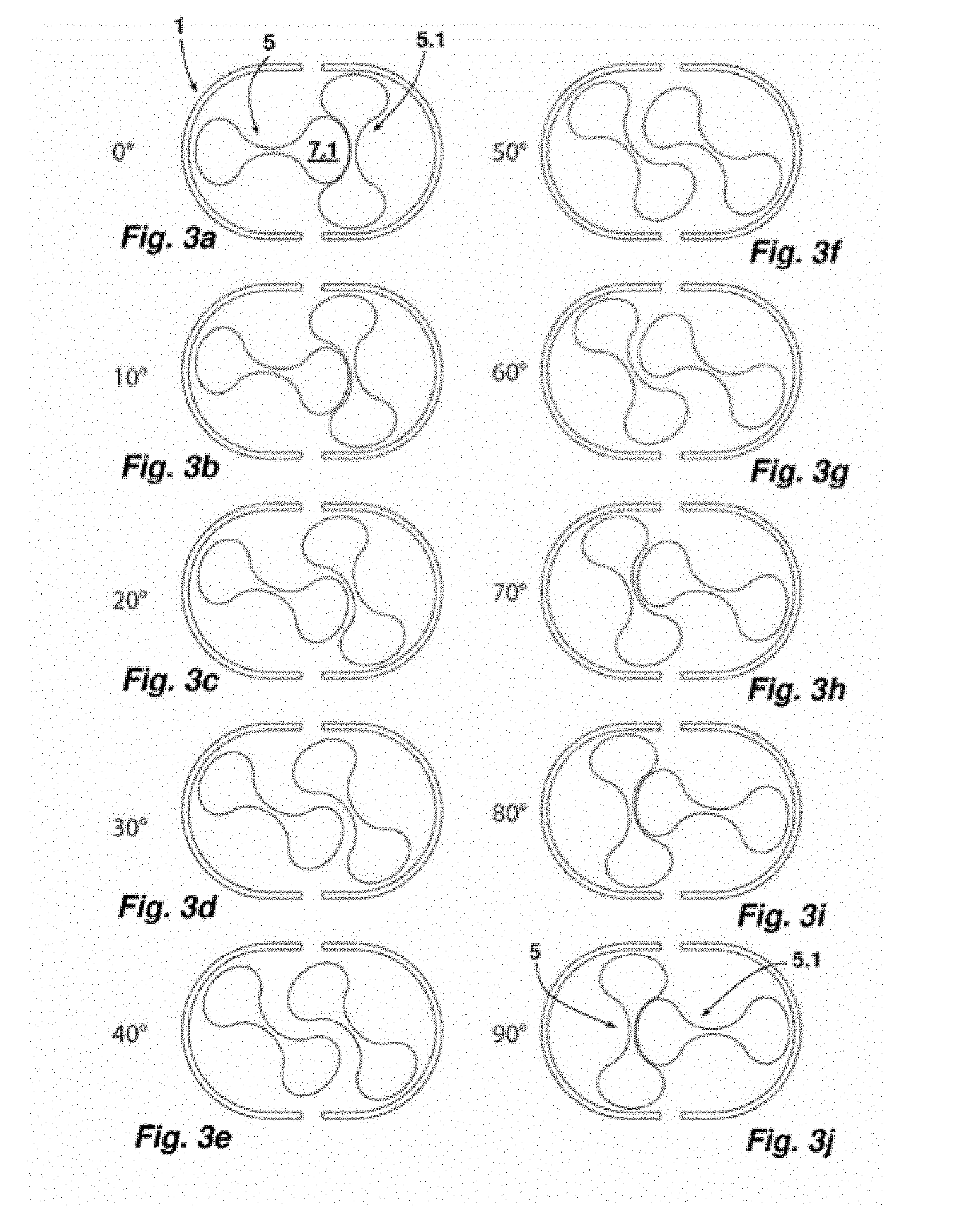
[0022] FIGS. 3a to 3j show a sequence of different positions of the styling bodies of the hair styling device of FIG. 1 to each other in a rotating drive of the styling bodies within a range of rotation angles of 90.degree.,
[0023] FIGS. 4a, 4b show a schematic representation of the hair styling device of previous figures during the process of styling hair in two different positions of its styling bodies,
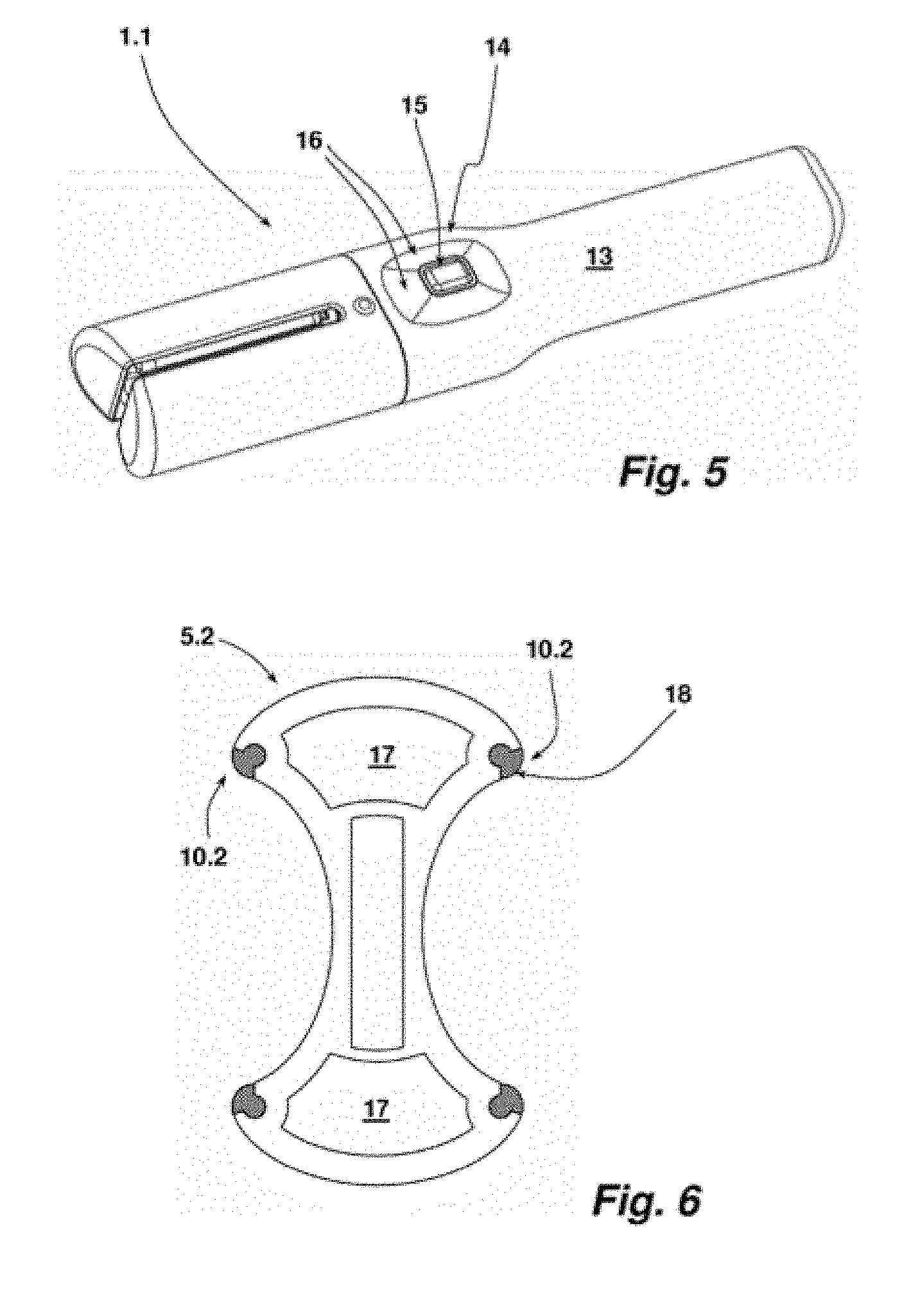
[0024] FIG. 5 shows a schematic perspective view of a further hair styling device of the present disclosure, and
[0025] FIG. 6 shows one of the two styling bodies of the hair styling device of FIG. 5 in a cross-sectional representation.
[0026] Before further explaining the depicted embodiments, it is to be understood that the present disclosure is not limited in its application to the details of the particular arrangements shown, since the present disclosure is capable of other embodiments. It is intended that the embodiments and figures disclosed herein are to be considered illustrative rather than limiting. Also, the terminology used herein is for the purposes of description and not limitation.
DETAILED DESCRIPTION
[0027] A hair styling device 1 comprises two arms 2, 2.1, which are pivotally connected to each other. FIG. 1 shows the hair styling device 1 having closed arms 2, 2.1. The arms 2, 2.1 may be separated from each other in the direction of the block arrows, shown in FIG. 1, for opening the hair styling device. FIG. 2 shows the hair styling device 1 in a side view, in which the articulated position of arms 2, 2.1 may be seen. The pivot joint is shown in FIG. 2 at 3. The arm 2.1 penetrates a section of arm 2 around the joint 3 and carries at its other end a handle 4. In order to open the hair styling device 1, whereby the arms 2, 2.1 are separated for receiving a hair strand, the handle 4 is lifted and thus moved away from the grip part 5. In the position of use of the hair styling device 1 shown in figures, both arms 2, 2.1 are locked, wherein the locking is released by acting on the handle 4.
[0028] Each arm 2, 2.1 carries a styling body 5, 5.1. The styling bodies 5, 5.1 in both arms 2, 2.1 are identical. The styling body 5 is described in the following, and the same description is valid for the other styling body 5.1 as well.
[0029] The body 5 is ultimately a styling body having an approximately strip-shaped appearance with a longitudinal extension as shown in the side view in FIG. 2. FIG. 1 shows the styling body 5 in a front side view and thus with reference to its cross-sectional geometry. The cross-sectional geometry of the styling body 5 is bone-shaped. Thus, the styling body 5 is provided with two head sections 7, 7.1, which are thickened with respect to a central section 6. The head section 7 has a convexly curved shell surface 8. In the plane of the central longitudinal plane, on the outer side of the shell surface 8 a central apex 9 is positioned. The radius of curvature in the area of the central apex 9 is larger than in the section of the head section 7, through which its largest width is defined. In this position two side apexes 10, 10.1 are provided. The head section 7.1 is configured as the head section 7. Between both head sections 7, 7.1 the already described central section 6 is provided. It has, at both its shell surface sides, a concavely curved shell surface. The shell surface of the head sections 7, 7.1 is continuously merged to the tapered surface of the central section 6. The axis of rotation of the styling body 5 is indicated in FIG. 1 and provided with reference numeral 11. The styling body 5 is driven in the direction of rotation indicated by the arrow in FIG. 1.
[0030] The styling body 5 in the example shown is a section made of an extruded aluminum profile having a smooth typically polished outer shell surface. The head sections 7, 7.1 are hollow chambers. In each hollow chamber of the head sections 7, 7.1 a heating element is inserted, such as a PCT-heating element. The hollow configuration of the head sections 7, 7.1 and the heating element housed therein are not shown in the figures. The heating elements inserted in the hollow chamber of the head sections 7, 7.1 heat the shell surface 8 of the styling body 5. Due to the good heat conductivity of the material used for the styling body 5, the shell surface of the styling body 5 has a homogeneous surface temperature during heating.
[0031] The radius of curvature in the area of the central apex 9 of the styling body 5 corresponds to the radius of curvature of the concave formation of the shell surface in the area of the central section 6, which forms its tapering 12.
[0032] FIG. 1 shows both styling bodies 5, 5.1 in the position of use of the hair styling device 1, and thus having closed arms 2, 2.1. The axes of rotation 11, 11.1 of the styling bodies 5, 5.1 and the configuration of the respective tapering 12 and the contour of the head sections 7 or 7.1 entering the same during use of the hair styling device 1 are adapted to each other in such a way that a contact between the styling bodies 5, 5.1 during a rotational movement thereof is excluded.
[0033] The sequence of FIGS. 3a to 3j shows the hair styling device 1 in different positions of its styling bodies 5, 5.1. In FIG. 3, the styling body 5 is directed horizontally and the styling body 5.1 is directed vertically. This position of both styling bodies 5, 5.1 to each other is evidenced by the insertion of the head section 7.1 of styling body 5 into the complementary tapering of styling body 5.1. Insofar, the head sections 7, 7.1 in the hair styling device 1 form elevations and the taperings 12 form recesses and thus the contouring of the shell surface of styling bodies 5, 5.1. A hair styling gap is provided between both styling bodies 5, 5.1. This reciprocal position shown in FIG. 3a of both styling bodies 5, 5.1 corresponds to a configuration having the smallest width of the hair styling gap. The remaining hair styling gap in the example shown is 1.0 mm, for example.
[0034] Both styling bodies 5, 5.1 are driven by means of an electric motor and a distribution gear connected downstream of the electric motor, while being cinematically coupled to each other about their rotational movement. In the example shown this occurs through two spur and bevel gears engaged to each other, which are positioned near the joint 3. A movement of the styling body 5 may thus be performed without a corresponding rotational movement of styling body 5.1.
[0035] In order to style a hair strand, both styling bodies 5, 5.1 are rotatably driven. The sequence of FIGS. 3a to 3j shows the different positions of the styling bodies 5, 5.1 to each other when performing a rotational movement of 90 degrees. After a 90-degree rotation, the styling body 5 is directed vertically and the styling body 5.1 is directed horizontally (see FIG. 3j). This position corresponds to the position of FIG. 3a with the hair styling gap at its smallest width. In this movement process, it is interesting that the width of the hair styling gap, starting from a position of the styling bodies 5, 5.1, as shown in FIG. 3a, initially increases, in particular up to an angle of 45 degrees and then drops again, until upon inserting the head section of styling body 5.1 into the tapering 12 of styling body 5, the smallest width of the hair styling gap is reached again. This repeats cyclically in the course of one rotational movement of the styling bodies 5, 5.1.
[0036] Through this measure, not only is a hair strand inserted in the hair styling gap successively drawn in, but also a relatively large curl or wave is formed in a particularly effective way.
[0037] FIG. 4a shows the hair styling device 1 with an inserted hair strand H and styling bodies 5, 5.1 in a position according to FIG. 3. The hair strand H has been inserted, after the arms 2, 2.1 have been previously opened. The opening of the hair styling device 1 for inserting or extracting a hair strand may be performed at each position of the styling bodies 5, 5.1. Then, the arms 2, 2.1 are again closed. The position shown in FIGS. 3a and 3j of the styling bodies 5, 5.1 to each other having the smallest gap width are positions in the course of the styling process. In these positions, the hair to be styled is subject to pressure, since the hair strand H has a thickness of slightly more than 1 mm and thus is slightly thicker than the minimum width of the hair styling gap. In this position the central apex of one head section of the one styling body 5 faces the apex of a tapering of the other styling body 5.1 and the gap width for hair styling is minimal. The otherwise continuous rotational movement of the styling bodies 5, 5.1 is interrupted for a certain period, for example 1 to 2 seconds. At this point a curl or wave apex is introduced into the hair strand H by applying pressure and temperature. Further rotation of the styling bodies 5, 5.1 to 90 degrees occurs with a continuous drive, before the styling bodies are in a position corresponding to FIG. 3j. The drive of the styling bodies 5, 5.1 is again shortly interrupted to impress the successive curl or wave apex in the hair strand H. This is repeated until the entire hair strand has been drawn through the hair styling device 1.
[0038] The phases of hair styling between said apex impressing phases also contributes to the hair styling.
[0039] The head sections of the two styling bodies 5, 5.1, to which the hair is applied, act due to the rotation of the styling bodies 5, 5.1 in the manner of edges on which the hair strand H to be formed is drawn past. This causes a preheating of the hair strand and a pre-configuration of the same before the impressing step in the 90-degree positions of the styling bodies 5, 5.1 to each other. For an effective pre-configuration, the side apexes 10, 10.1 of the head sections of the styling bodies 5, 5.1 are designed with a smaller radius of curvature than the center vertices. This is the case in the described embodiment. Another possible embodiment allows the head sections to have a cross-sectional or approximately circular cross-sectional shape deviating from the illustrated oval shape.
[0040] In the hair styling process described above, a certain impressing time is provided when the styling bodies 5, 5.1 are in their 90-degree position relative to each other (corresponding to FIGS. 3a and 3j). This impressing time is typically adjustable, so that in this way influence on hair styling can be taken. The curl or wave apexes are accentuated with a longer impressing time. It is also possible to use a hair-styling process in which the styling bodies 5, 5.1 are driven continuously and without interruption by the impressing time.
[0041] Influence on the hair styling may also be exerted through the rotational speed of the styling bodies 5, 5.1, as this, if an impressing time is provided, defines the length of the hair styling process on the hair strands to be styled, which is performed without an abutment.
[0042] The illustration of the strand of hair to be formed in FIGS. 4a, 4b make it clear that in the course of the rotational movement of the styling bodies 5, 5.1 and the changing width of the hair styling gap, the hair styling device 1 can be moved without pulling on the strand of hair. This can be used to influence the shape of the curls or waves. If larger curls or waves are to be formed, this will be done in the opposite direction of the insertion direction of the hair strand H.
[0043] The insertion direction of the hair strand H is indicated in FIGS. 4a, 4b with an arrow.
[0044] FIG. 5 shows another hair styling device 1.1 of the present disclosure. This is in principle constructed as the hair styling device 1, which has been described in detail in the preceding figures. The hair styling device 1.1 is provided in the area of its handle 13, with a control switch arrangement 14. The control switch arrangement 14 comprises a central key 15 and adjacent keys 16.
[0045] Through these, the operating mode of the hair styling device 1.1 can be adjusted. This includes setting of the desired hair styling temperature and hair styling program, which in turn influences the drive of the styling bodies. The hair styling device 1.1 also has an acceleration sensor for detecting longitudinal axial rotational movements. This makes it possible to start and stop the drive of the styling bodies. A short, fast turning movement over a small turning angle in one direction is the starting signal. A rotation movement corresponding to a few degrees of rotation in the opposite direction is the stop signal. The hair styling program to be performed has been previously selected. Therefore, the hair styling device 1.1 can then be used without requiring the operation of the control switch arrangement. Finally, it is usual for the strand of hair to be curled with the same operating mode of the hair styling device 1.1.
[0046] The operating mode can be varied with respect to the drive in the hair styling device 1.1, for example, by a differently intermittent drive. Of course, a continuous drive of the styling bodies may also be set. In an intermittent drive, the styling bodies remain at predetermined locations, typically in the 90.degree. positions where the apex of a head section opposes the apex of a tapering of the central section, for a predetermined period of time. Such brief interruption may last one or more seconds. The interruption is the same in every 90.degree. position, depending on the program selected, but may also be different. In this way the resulting hair styling may be individually adjusted. In the 90.degree. positions of both styling bodies to each other, maximum heat is applied to the hair.
[0047] In the hair styling device 1.1, two styling bodies 5.2 are used (see FIG. 6). These styling bodies 5.2 are constructed in principle, as the styling bodies 5, 5.1 of the embodiment of the hair styling device 1 of the preceding figures. In the styling body 5.2 PTC heating elements 17 inserted therein are shown, through which the head sections are heated. At the side apexes 10.2 and thus at the apexes between the terminal convex shell surface section and the concavely curved shell surface section of the central section, hair entrainers 18 are arranged on the styling body 5.2. These are used in slots provided on the styling body 5.2, which follow the longitudinal extension. The hair entrainers 18 are made of silicone and cause a hair entrainment due to their surface adhesion force.
[0048] It may also be conceived, that a hair entrainer is provided on one side of opposing sides of the apexes 10.2 of the head sections of the styling body 5.2 and on the other side a hair conditioner applicator is provided. The styling body 5.2 is then driven in the direction in which one side apex 10.2 initially contacts the hair with the hair entrainer and the other side apex of the styling body contacts the hair only after it has moved through the 90.degree. position of both styling bodies to each other and thus applies a conditioner onto the hair strand at the end of the hair styling process.
[0049] The developments of the hair styling device 1.1 described herein may also be used for the hair styling device 1 of the preceding figures.
[0050] The invention was described based on exemplary embodiments. A person skilled in the art will derive numerous embodiments for implementing the invention without departing from the scope of the present claims. While a number of aspects and embodiments have been discussed above, those of skill in the art will recognize certain modifications, permutations, additions and sub-combinations therefore. It is therefore intended that the following appended claims hereinafter introduced are interpreted to include all such modifications, permutations, additions and sub-combinations, which are within their true spirit and scope. Each embodiment described herein has numerous equivalents.
[0051] The terms and expressions which have been employed are used as terms of description and not of limitation, and there is no intention in the use of such terms and expressions of excluding any equivalents of the features shown and described or portions thereof, but it is recognized that various modifications are possible within the scope of the invention claimed. Thus, it should be understood that although the present invention has been specifically disclosed by preferred embodiments and optional features, modification and variation of the concepts herein disclosed may be resorted to by those skilled in the art, and that such modifications and variations are considered to be within the scope of this invention as defined by the appended claims. Whenever a range is given in the specification, all intermediate ranges and subranges, as well as all individual values included in the ranges given are intended to be included in the disclosure. When a Markush group or other grouping is used herein, all individual members of the group and all combinations and sub-combinations possible of the group are intended to be individually included in the disclosure.
[0052] In general, the terms and phrases used herein have their art-recognized meaning, which can be found by reference to standard texts, journal references and contexts known to those skilled in the art. The above definitions are provided to clarify their specific use in the context of the invention.
LIST OF REFERENCES
[0053] 1, 1.1 hair styling device [0054] 2, 2.1 arm [0055] 3 joint [0056] 4 handle [0057] 5, 5.1, 5.2 styling body [0058] 6 central section [0059] 7.7 head section [0060] 8 shell surface [0061] 9 central apex [0062] 10, 10.1, 10.2 side apexes [0063] 11, 11.1 axis of rotation [0064] 12 tapering [0065] 13 grip [0066] 14 control switch arrangement [0067] 15 key [0068] 16 key [0069] 17 PTC heating element [0070] 18 hair entrainer [0071] G grip section [0072] H hair strand
* * * * *
D00000
D00001
D00002
D00003
D00004
XML
uspto.report is an independent third-party trademark research tool that is not affiliated, endorsed, or sponsored by the United States Patent and Trademark Office (USPTO) or any other governmental organization. The information provided by uspto.report is based on publicly available data at the time of writing and is intended for informational purposes only.
While we strive to provide accurate and up-to-date information, we do not guarantee the accuracy, completeness, reliability, or suitability of the information displayed on this site. The use of this site is at your own risk. Any reliance you place on such information is therefore strictly at your own risk.
All official trademark data, including owner information, should be verified by visiting the official USPTO website at www.uspto.gov. This site is not intended to replace professional legal advice and should not be used as a substitute for consulting with a legal professional who is knowledgeable about trademark law.