Hvac Controller With Wireless Network Based Occupancy Detection And Control
Bergman; Gabriel A. ; et al.
U.S. patent application number 16/154481 was filed with the patent office on 2019-02-07 for hvac controller with wireless network based occupancy detection and control. The applicant listed for this patent is Honeywell International Inc.. Invention is credited to Gabriel A. Bergman, Neo Liu.
| Application Number | 20190041881 16/154481 |
| Document ID | / |
| Family ID | 57188772 |
| Filed Date | 2019-02-07 |

| United States Patent Application | 20190041881 |
| Kind Code | A1 |
| Bergman; Gabriel A. ; et al. | February 7, 2019 |
HVAC CONTROLLER WITH WIRELESS NETWORK BASED OCCUPANCY DETECTION AND CONTROL
Abstract
An HVAC controller that can detect if a user's mobile wireless device is currently connected to and recognized by a building's wireless local area network is disclosed. Depending on whether or not the user's mobile wireless device is currently connected to and recognized by the building's wireless local area network, the HVAC controller basis its control on unoccupied or occupied settings.
| Inventors: | Bergman; Gabriel A.; (New Brighton, MN) ; Liu; Neo; (Tianjin, CN) | ||||||||||
| Applicant: |
|
||||||||||
|---|---|---|---|---|---|---|---|---|---|---|---|
| Family ID: | 57188772 | ||||||||||
| Appl. No.: | 16/154481 | ||||||||||
| Filed: | October 8, 2018 |
Related U.S. Patent Documents
| Application Number | Filing Date | Patent Number | ||
|---|---|---|---|---|
| 15214225 | Jul 19, 2016 | 10133283 | ||
| 16154481 | ||||
| 13559443 | Jul 26, 2012 | 9477239 | ||
| 15214225 | ||||
| Current U.S. Class: | 1/1 |
| Current CPC Class: | F24F 11/62 20180101; G05D 23/1905 20130101; H04L 12/282 20130101; G05B 15/02 20130101; H04L 12/2809 20130101; F24F 11/0034 20130101; H04L 12/2816 20130101; F24F 11/65 20180101; F24F 2011/0064 20130101; G05D 23/1904 20130101; F24F 2110/10 20180101; F24F 2120/12 20180101; F24F 11/30 20180101; G05D 23/1927 20130101; H04W 64/00 20130101; F24F 2120/10 20180101; F24F 11/58 20180101; G05D 23/19 20130101; G05B 2219/2614 20130101; F24F 11/006 20130101; F24F 2110/20 20180101; G05B 2219/33192 20130101; G05B 2219/2642 20130101; F24F 2011/0071 20130101; H04L 12/2827 20130101 |
| International Class: | G05D 23/19 20060101 G05D023/19; H04W 64/00 20090101 H04W064/00; F24F 11/62 20180101 F24F011/62; H04L 12/28 20060101 H04L012/28; F24F 11/30 20180101 F24F011/30 |
Claims
1. An HVAC controller for controlling one or more components of an HVAC system of a building, the HVAC controller comprising: a memory; a wireless transceiver for wirelessly communicating over a wireless local area network in the building; a controller configured to provide control signals to the one or more components of the HVAC system, the controller further configured to monitor the wireless local area network in the building via the wireless transceiver and determine if a mobile wireless device known by the HVAC controller to be associated with a known user is currently wirelessly connected to the wireless local area network or not, wherein: when the mobile wireless device known by the HVAC controller to be associated with the known user is currently wirelessly connected to the wireless local area network, the controller is configured to access a user profile associated with the known user and operate the HVAC system in accordance with an occupied operational setting specified by the user profile; and when the mobile wireless device known by the HVAC controller to be associated with the known user is currently not wirelessly connected to the wireless local area network, the controller is configured to operate the HVAC system in accordance with an unoccupied temperature setpoint.
2. The HVAC controller of claim 1, wherein the wireless local area network of the building is hosted by a network host device that is separate from the HVAC controller.
3. The HVAC controller of claim 1, wherein the wireless local area network of the building is hosted by the HVAC controller.
4. The HVAC controller of claim 1, wherein the mobile wireless device known by the HVAC controller to be associated with the known user comprises a known user's smart phone.
5. The HVAC controller of claim 1, wherein the mobile wireless device known by the HVAC controller to be associated with the known user comprises a known user's fob.
6. The HVAC controller of claim 1, wherein the wireless local area network comprises a WiFi network.
7. The HVAC controller of claim 1, wherein the wireless local area network operates according the Bluetooth protocol.
8. The HVAC controller of claim 1, wherein the wireless local area network operates according the Zigbee, IrDa, Dedicated Short Range Communication (DSRC), EnOcean, or Redlink protocol.
9. The HVAC controller of claim 1, wherein the unoccupied temperature setpoint is specified by the user profile.
10. An HVAC controller for controlling one or more components of an HVAC system of a building, the HVAC controller comprising: a memory; a wireless transceiver for wirelessly communicating over a wireless local area network in the building; a controller configured to provide control signals to the one or more components of the HVAC system, the controller further configured to monitor the wireless local area network in the building via the wireless transceiver and determine which if any of a plurality of mobile wireless devices known to the HVAC controller are currently wirelessly connected to the wireless local area network or not, wherein: when one or more of the plurality of mobile wireless devices known to the HVAC controller are currently wirelessly connected to the wireless local area network, the controller is configured to operate the HVAC system in accordance with an occupied temperature setting; and when none of the plurality of mobile wireless devices known to the HVAC controller are currently not wirelessly connected to the wireless local area network, the controller is configured to operate the HVAC system in accordance with an unoccupied temperature setpoint.
11. The HVAC controller of claim 10, wherein each of the plurality of mobile wireless devices known to the HVAC controller has a corresponding user profile, and wherein when only one of the plurality of mobile wireless devices known to the HVAC controller is currently wirelessly connected to the wireless local area network, the controller is configured to operate the HVAC system in accordance with the occupied temperature setting specified in the user profile that corresponds to the mobile wireless device that is currently wirelessly connected to the wireless local area network.
12. The HVAC controller of claim 10, wherein each of the plurality of mobile wireless devices known to the HVAC controller has a corresponding user profile, and wherein when two or more of the plurality of mobile wireless devices known to the HVAC controller are currently wirelessly connected to the wireless local area network, the controller is configured to operate the HVAC system in accordance with the occupied temperature setting specified in the user profile that corresponds to a highest priority mobile wireless device of the two or more of the plurality of mobile wireless devices that are currently wirelessly connected to the wireless local area network.
13. The HVAC controller of claim 12, wherein the highest priority mobile wireless device is determined by applying one or more rules.
14. The HVAC controller of claim 10, wherein the wireless local area network of the building is hosted by a network host device that is separate from the HVAC controller.
15. The HVAC controller of claim 10, wherein the wireless local area network of the building is hosted by the HVAC controller.
16. The HVAC controller of claim 10, wherein the plurality of mobile wireless devices known to the HVAC controller comprises one or more smart phones.
17. The HVAC controller of claim 10, wherein the plurality of mobile wireless devices known to the HVAC controller comprises one or more fobs.
18. The HVAC controller of claim 1, wherein the wireless local area network comprises a WiFi network or a Bluetooth network.
19. A method for controlling one or more components of an HVAC system of a building, the method comprising: monitoring a wireless local area network; determining which, if any, of one or more known mobile wireless device are currently wirelessly connected to the wireless local area network or not; when one or more of the known mobile wireless device are currently wirelessly connected to the wireless local area network, operate the HVAC system in accordance with an occupied temperature setting; and when none of the known mobile wireless device are currently wirelessly connected to the wireless local area network, operate the HVAC system in accordance with an unoccupied temperature setpoint.
20. The method of claim 19, wherein when two or more known mobile wireless device are currently wirelessly connected to the wireless local area network, operate the HVAC system in accordance with the occupied temperature setting specified in a user profile that corresponds to a highest ranking mobile wireless device of the two or more known mobile wireless devices that are currently wirelessly connected to the wireless local area network.
Description
[0001] This is a continuation of U.S. patent application Ser. No. 15/214,225, filed Jul. 19, 2016, and entitled "HVAC CONTROLLER WITH WIRELESS NETWORK BASED OCCUPANCY DETECTION AND CONTROL", which is a continuation of U.S. patent application Ser. No. 13/559,443, filed Jul. 26, 2012, and entitled "HVAC CONTROLLER WITH WIRELESS NETWORK BASED OCCUPANCY DETECTION AND CONTROL", both of which are incorporated herein by reference.
CROSS-REFERENCE TO RELATED APPLICATIONS
[0002] This application is related to application Ser. No. 13/559,470, filed Jul. 26, 2012, and entitled "METHOD OF ASSOCIATING AN HVAC CONTROLLER WITH AN EXTERNAL WEB SERVICE" and application Ser. No. 13/559,489, filed Jul. 26, 2012, and entitled "HVAC CONTROLLER HAVING A NETWORK-BASED SCHEDULING FEATURE", both incorporated herein by reference in their entireties for all purposes.
TECHNICAL FIELD
[0003] The present disclosure relates generally to HVAC systems, and more particularly to HVAC controllers that accommodate and/or facilitate control of an HVAC system from a remote location.
BACKGROUND
[0004] Heating, ventilation, and/or air conditioning (HVAC) systems are often used to control the comfort level within a building or other structure. Such HVAC systems typically include an HVAC controller that controls various HVAC components of the HVAC system in order to affect and/or control one or more environmental conditions within the building. In some cases, it may be desirable for a user to be able to affect the operation of an HVAC system from a remote location.
SUMMARY
[0005] The present disclosure pertains generally to HVAC systems, and more particularly to HVAC controllers that accommodate and/or facilitate control of an HVAC system from a remote location. In one illustrative embodiment, an HVAC controller includes a memory, a wireless transceiver for wirelessly sending and receiving data over a building's wireless local area network, and a controller configured to execute a program code stored in the memory for connecting the HVAC controller to the wireless local area network via the wireless transceiver and to detect if a mobile wireless device is currently connected to and recognized by the wireless local area network. The controller may further be configured to change at least one operational parameter setting of the HVAC system depending on whether the mobile wireless device is currently connected to and recognized by the wireless local area network or not.
[0006] In some cases, the controller is configured to execute a program code stored in the memory for detecting if a mobile wireless device, having a unique identifier, is currently enrolled in the wireless local area network by repeatedly broadcasting a query for the mobile wireless device over the wireless local area network. The controller may be configured to change at least one operational parameter setting of the HVAC system (e.g. a temperature set point) in accordance with an occupied mode upon receiving a response from the mobile wireless device to the query indicating occupancy of the building.
[0007] The preceding summary is provided to facilitate an understanding of some of the innovative features unique to the present disclosure, and is not intended to be a full description. A full appreciation of the disclosure can be gained by taking the entire specification, claims, drawings, and abstract as a whole.
BRIEF DESCRIPTION OF THE DRAWINGS
[0008] The disclosure may be more completely understood in consideration of the following description of various illustrative embodiments in connection with the accompanying drawings, in which:
[0009] FIG. 1 is a schematic view of an illustrative HVAC system servicing a building or structure;
[0010] FIG. 2 is a schematic view of an illustrative HVAC control system that may facilitate access and/or control of the HVAC system of FIG. 1;
[0011] FIG. 3 is a schematic block diagram of an illustrative HVAC controller;
[0012] FIG. 4 is a schematic view of an illustrative HVAC controller in communication with a mobile wireless device; and
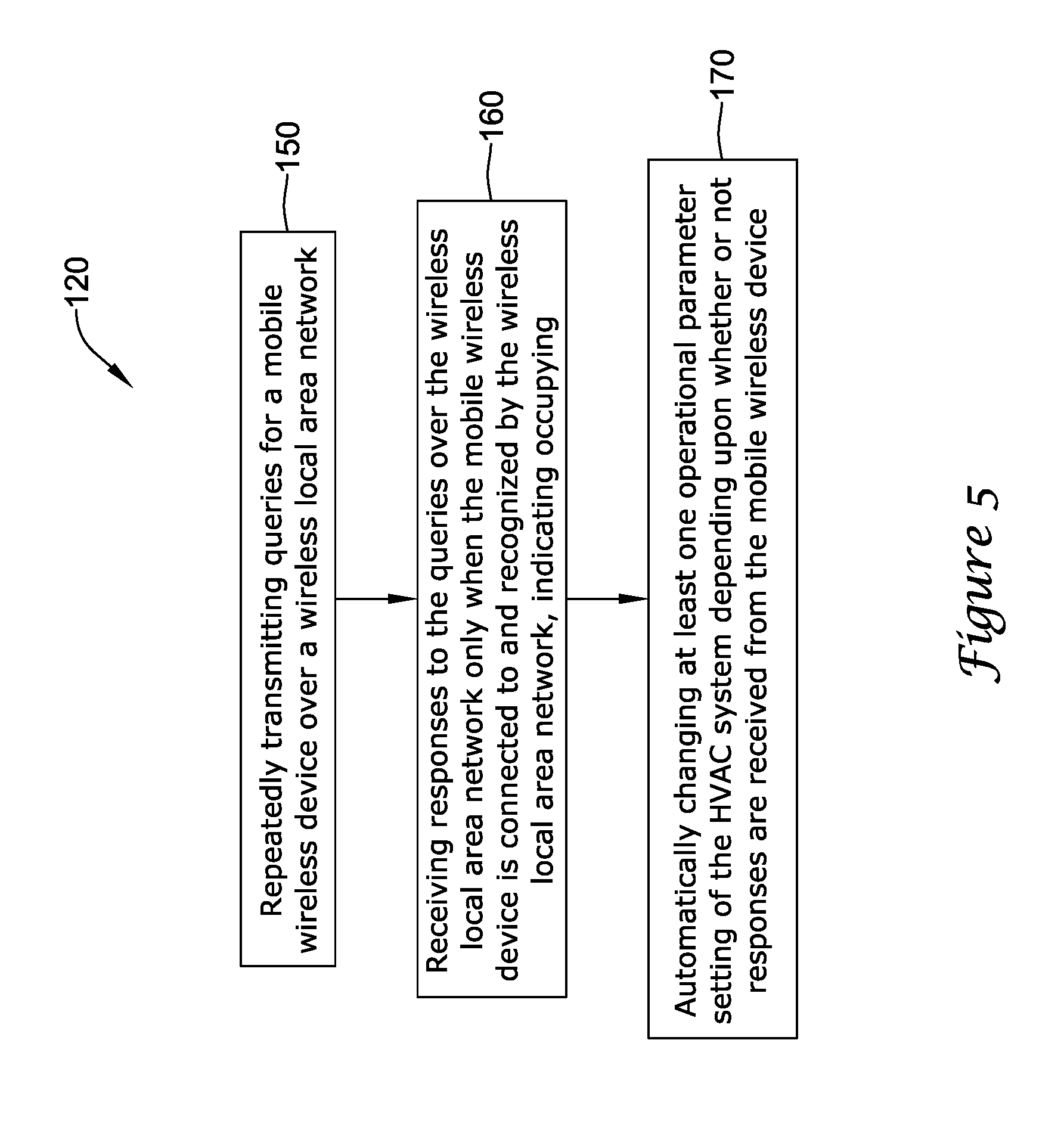
[0013] FIG. 5 is a flow chart of an illustrative method of controlling an HVAC system.
[0014] While the disclosure is amenable to various modifications and alternative forms, specifics thereof have been shown by way of example in the drawings and will be described in detail. It should be understood, however, that the intention is not to limit aspects of the disclosure to the particular illustrative embodiments described. On the contrary, the intention is to cover all modifications, equivalents, and alternatives falling within the spirit and scope of the disclosure.
DESCRIPTION
[0015] The following description should be read with reference to the drawings wherein like reference numerals indicate like elements throughout the several views. The description and drawings show several embodiments which are meant to illustrative in nature.
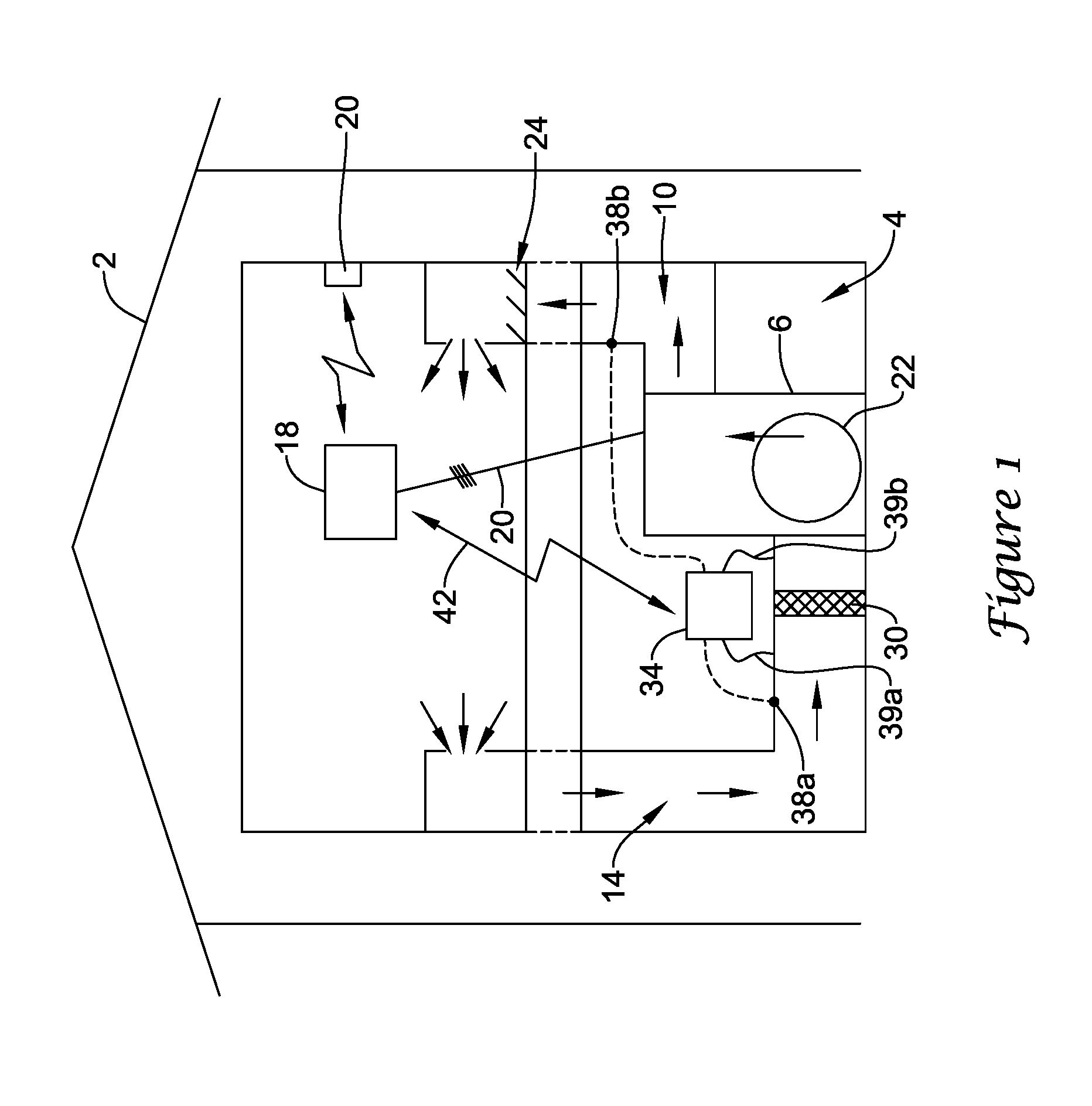
[0016] FIG. 1 is a schematic view of a building 2 having an illustrative heating, ventilation, and air conditioning (HVAC) system 4. While FIG. 1 shows a typical forced air type HVAC system, other types of HVAC systems are contemplated including, but not limited to, boiler systems, radiant heating systems, electric heating systems, cooling systems, heat pump systems, and/or any other suitable type of HVAC system, as desired. The illustrative HVAC system 4 of FIG. 1 includes one or more HVAC components 6, a system of ductwork and air vents including a supply air duct 10 and a return air duct 14, and one or more HVAC controllers 18. The one or more HVAC components 6 may include, but are not limited to, a furnace, a heat pump, an electric heat pump, a geothermal heat pump, an electric heating unit, an air conditioning unit, a humidifier, a dehumidifier, an air exchanger, an air cleaner, a damper, a valve, and/or the like.
[0017] It is contemplated that the HVAC controller(s) 18 may be configured to control the comfort level in the building or structure by activating and deactivating the HVAC component(s) 6 in a controlled manner. The HVAC controller(s) 18 may be configured to control the HVAC component(s) 6 via a wired or wireless communication link 20. In some cases, the HVAC controller(s) 18 may be a thermostat, such as, for example, a wall mountable thermostat, but this is not required in all embodiments. Such a thermostat may include (e.g. within the thermostat housing) or have access to a temperature sensor for sensing an ambient temperature at or near the thermostat. In some instances, the HVAC controller(s) 18 may be a zone controller, or may include multiple zone controllers each monitoring and/or controlling the comfort level within a particular zone in the building or other structure.
[0018] In the illustrative HVAC system 4 shown in FIG. 1, the HVAC component(s) 6 may provide heated air (and/or cooled air) via the ductwork throughout the building 2. As illustrated, the HVAC component(s) 6 may be in fluid communication with every room and/or zone in the building 2 via the ductwork 10 and 14, but this is not required. In operation, when a heat call signal is provided by the HVAC controller(s) 18, an HVAC component 6 (e.g. forced warm air furnace) may be activated to supply heated air to one or more rooms and/or zones within the building 2 via supply air ducts 10. The heated air may be forced through supply air duct 10 by a blower or fan 22. In this example, the cooler air from each zone may be returned to the HVAC component 6 (e.g. forced warm air furnace) for heating via return air ducts 14. Similarly, when a cool call signal is provided by the HVAC controller(s) 18, an HVAC component 6 (e.g. air conditioning unit) may be activated to supply cooled air to one or more rooms and/or zones within the building or other structure via supply air ducts 10. The cooled air may be forced through supply air duct 10 by the blower or fan 22. In this example, the warmer air from each zone may be returned to the HVAC component 6 (e.g. air conditioning unit) for cooling via return air ducts 14. In some cases, the HVAC system 4 may include an internet gateway or other device 20 that may allow one or more of the HVAC components, as described herein, to communicate over a wide area network (WAN) such as, for example, the Internet.
[0019] In some cases, the system of vents or ductwork 10 and/or 14 can include one or more dampers 24 to regulate the flow of air, but this is not required. For example, one or more dampers 24 may be coupled to one or more HVAC controller(s) 18, and can be coordinated with the operation of one or more HVAC components 6. The one or more HVAC controller(s) 18 may actuate dampers 24 to an open position, a closed position, and/or a partially open position to modulate the flow of air from the one or more HVAC components to an appropriate room and/or zone in the building or other structure. The dampers 24 may be particularly useful in zoned HVAC systems, and may be used to control which zone(s) receives conditioned air from the HVAC component(s) 6.
[0020] In many instances, one or more air filters 30 may be used to remove dust and other pollutants from the air inside the building 2. In the illustrative example shown in FIG. 1, the air filter(s) 30 is installed in the return air duct 14, and may filter the air prior to the air entering the HVAC component 6, but it is contemplated that any other suitable location for the air filter(s) 30 may be used. The presence of the air filter(s) 30 may not only improve the indoor air quality, but may also protect the HVAC components 6 from dust and other particulate matter that would otherwise be permitted to enter the HVAC component.
[0021] In some cases, and as shown in FIG. 1, the illustrative HVAC system 4 may include an equipment interface module (EIM) 34. When provided, the equipment interface module 34 may be configured to measure or detect a change in a given parameter between the return air side and the discharge air side of the HVAC system 4. For example, the equipment interface module 34 may be adapted to measure a difference in temperature, flow rate, pressure, or a combination of any one of these parameters between the return air side and the discharge air side of the HVAC system 4. In some cases, the equipment interface module 34 may be adapted to measure the difference or change in temperature (delta T) between a return air side and discharge air side of the HVAC system 4 for the heating and/or cooling mode. The delta T for the heating mode may be calculated by subtracting the return air temperature from the discharge air temperature (e.g. delta T=discharge air temp.-return air temp.). For the cooling mode, the delta T may be calculated by subtracting the discharge air temperature from the return air temperature (e.g. delta T=return air temp.-discharge air temp.).
[0022] In some cases, the equipment interface module 34 may include a first temperature sensor 38a located in the return (incoming) air duct 14, and a second temperature sensor 38b located in the discharge (outgoing or supply) air duct 10. Alternatively, or in addition, the equipment interface module 34 may include a differential pressure sensor including a first pressure tap 39a located in the return (incoming) air duct 14, and a second pressure tap 39b located downstream of the air filter 30 to measure a change in a parameter related to the amount of flow restriction through the air filter 30. In some cases, the equipment interface module 34, when provided, may include at least one flow sensor that is capable of providing a measure that is related to the amount of air flow restriction through the air filter 30. In some cases, the equipment interface module 34 may include an air filter monitor. These are just some examples.
[0023] When provided, the equipment interface module 34 may be configured to communicate with the HVAC controller 18 via, for example, a wired or wireless communication link 42. In other cases, the equipment interface module 34 may be incorporated or combined with the HVAC controller 18. In either cases, the equipment interface module 34 may communicate, relay or otherwise transmit data regarding the selected parameter (e.g. temperature, pressure, flow rate, etc.) to the HVAC controller 18. In some cases, the HVAC controller 18 may use the data from the equipment interface module 34 to evaluate the system's operation and/or performance. For example, the HVAC controller 18 may compare data related to the difference in temperature (delta T) between the return air side and the discharge air side of the HVAC system 4 to a previously determined delta T limit stored in the HVAC controller 18 to determine a current operating performance of the HVAC system 4.
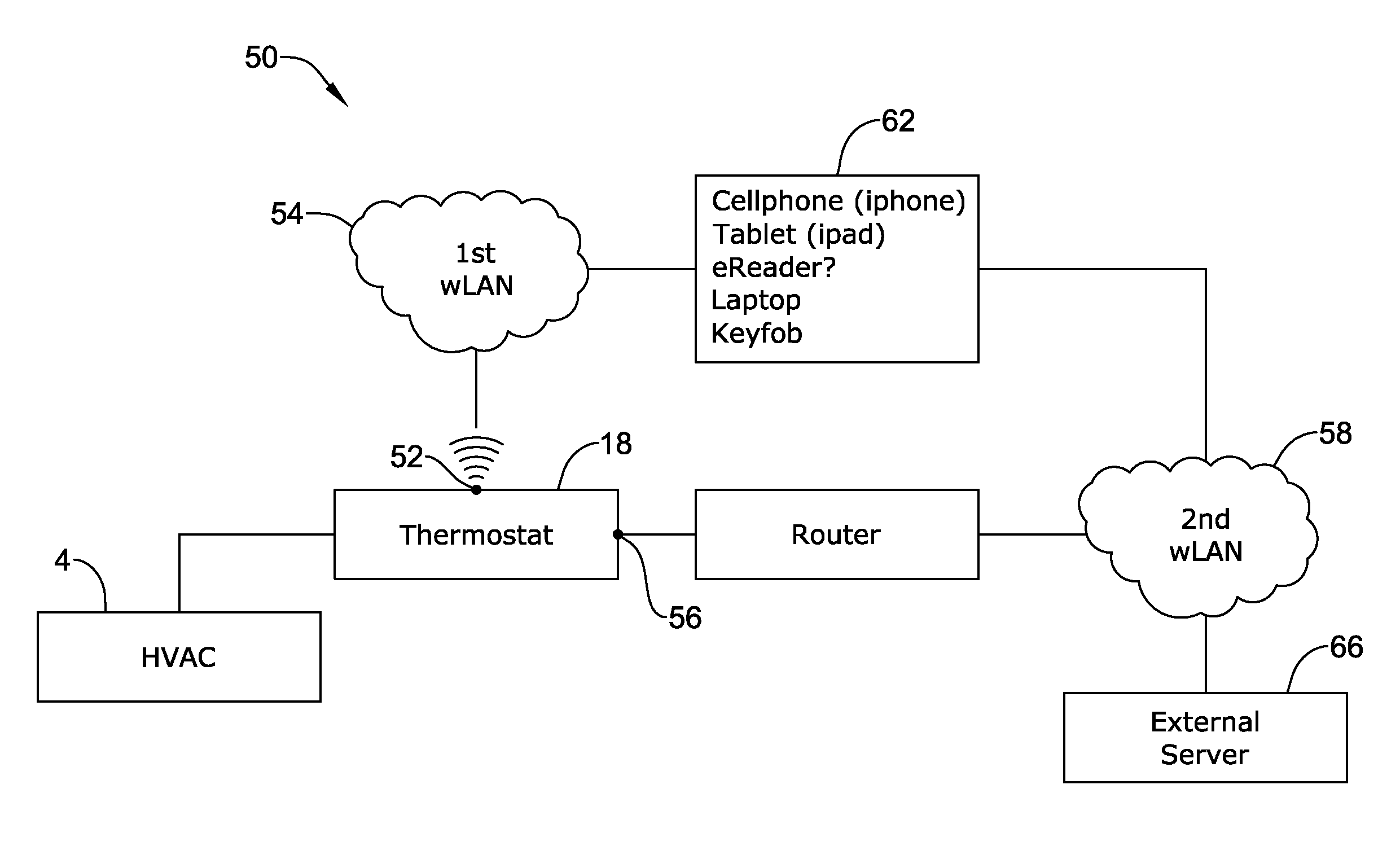
[0024] FIG. 2 is a schematic view of an HVAC control system 50 that facilitates remote access and/or control of the HVAC system 4 shown in FIG. 1. The illustrative HVAC control system 50 includes an HVAC controller, as for example, HVAC controller 18 (see FIG. 1) that is configured to communicate with and control one or more components 6 of the HVAC system 4. As discussed above, the HVAC controller 18 may communicate with the one or more components 6 of the HVAC system 4 via a wired or wireless link. Additionally, the HVAC controller 18 may be adapted to communicate over one or more wired or wireless networks that may accommodate remote access and/or control of the HVAC controller 18 via another device such as a cell phone, tablet, reader, laptop computer, key fob, or the like. As shown in FIG. 2, the HVAC controller 18 may include a first communications port 52 for communicating over a first network 54, and in some cases, a second communications port 56 for communicating over a second network 58. In some cases, the first network 54 may be a wireless local area network (LAN), and the second network 58 (when provided) may be a wide area network or global network (WAN) including, for example, the Internet. In some cases, the wireless local area network 54 may provide a wireless access point and/or a network host device that is separate from the HVAC controller 18. In other cases, the wireless local area network 54 may provide a wireless access point and/or a network host device that is part of the HVAC controller 18. In some cases, the wireless local area network 54 may include a local domain name server (DNS), but this is not required for all embodiments. In some cases, the wireless local area network 54 may be an ad-hoc wireless network, but this is not required.
[0025] Depending upon the application and/or where the HVAC user is located, remote access and/or control of the HVAC controller 18 may be provided over the first network 54 and/or the second network 58. A variety of mobile wireless devices 62 may be used to access and/or control the HVAC controller 18 from a remote location (e.g. remote from HVAC Controller 18) over the first network 54 and/or second network 58 including, but not limited to, mobile phones including smart phones, PDAs, tablet computers, laptop or personal computers, wireless network-enabled key fobs, e-Readers and the like.
[0026] In many cases, the mobile wireless devices 62 are configured to communicate wirelessly over the first network 54 and/or second network 58 with the HVAC controller 18 via one or more wireless communication protocols including, but not limited to, cellular communication, ZigBee, REDLINK.TM., Bluetooth, WiFi, IrDA, dedicated short range communication (DSRC), EnOcean, and/or any other suitable common or proprietary wireless protocol, as desired.
[0027] In some cases, the HVAC controller 18 may be programmed to communicate over the second network 58 with an external web service hosted by one or more external web servers 66. A non-limiting example of such an external web service is Honeywell's TOTAL CONNECT.TM. web service. The HVAC controller 18 may be configured to upload selected data via the second network 58 to the external web service where it may be collected and stored on the external web server 66. In some cases, the data may be indicative of the performance of the HVAC system 4. Additionally, the HVAC controller 18 may be configured to receive and/or download selected data, settings and/or services including software updates from the external web service over the second network 58. The data, settings and/or services may be received automatically from the web service, downloaded periodically in accordance with a control algorithm, and/or downloaded in response to a user request. In some cases, for example, the HVAC controller 18 may be configured to receive and/or download an HVAC operating schedule and operating parameter settings such as, for example, temperature set points, humidity set points, start times, end times, schedules, window frost protection settings, and/or the like. In some instances, the HVAC controller 18 may be configured to receive one or more user profiles having at least one operational parameter setting that is selected by and reflective of a user's preferences. Additionally, the HVAC controller 18 may be configured to receive local weather data, weather alerts and/or warnings, major stock index ticker data, and/or news headlines over the second network 58. These are just some examples.
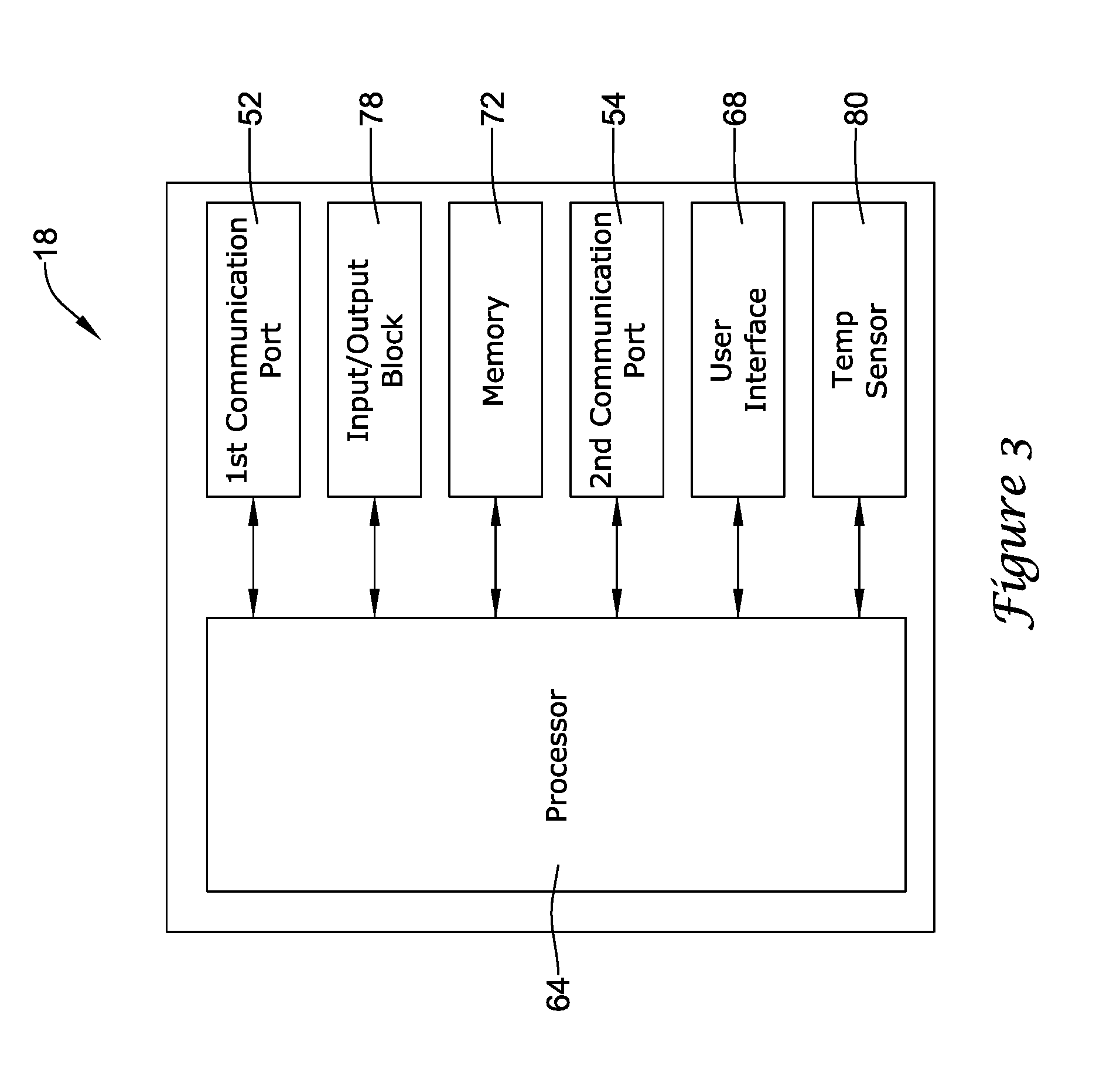
[0028] FIG. 3 is a schematic view of an illustrative HVAC controller 18 that may be accessed and/or controlled from a remote location over the first network 54 and/or the second network 58 (FIG. 2) using a mobile wireless device 62 such as, for example, a smart phone, a PDA, a tablet computer, a laptop or personal computer, a wireless network-enabled key fob, an e-Reader, and/or the like. In some instances, the HVAC controller 18 may be a thermostat, but this is not required. As shown in FIGS. 2 and 3, the HVAC controller 18 may include a first communications port 52 for communicating over a first network (e.g. wireless LAN) and a second communications port 56 for communicating over a second network (e.g. WAN or the Internet). The first communications port 52 can be a wireless communications port including a wireless transceiver for wirelessly sending and/or receiving signals over a first wireless network 54. Similarly, the second communications port 56 may be a wireless communications port including a wireless transceiver for sending and/or receiving signals over a second wireless network 58. In some cases, the second communications port 56 may be in communication with a wired or wireless router or gateway for connecting to the second network, but this is not required. In some cases, the router or gateway may be integral to the HVAC controller 18 or may be provided as a separate device. Additionally, the illustrative HVAC controller 18 may include a processor (e.g. microprocessor, microcontroller, etc.) 64 and a memory 72. The HVAC controller 18 may also include a user interface 68, but this is not required.
[0029] In some cases, HVAC controller 18 may include a timer (not shown). The timer may be integral to the processor 64 or may be provided as a separate component. The HVAC controller 18 may also optionally include an input/output block (I/O block) 78 for receiving one or more signals from the HVAC system 4 and/or for providing one or more control signals to the HVAC system 4. For example, the I/O block 78 may communicate with one or more HVAC components 6 of the HVAC system 4. Alternatively, or in addition to, the I/O block 78 may communicate with another controller, which is in communication with one or more HVAC components of the HVAC system 4, such as a zone control panel in a zoned HVAC system, equipment interface module (EIM) (e.g. EIM 34 shown in FIG. 1) or any other suitable building control device.
[0030] The HVAC controller 18 may also include an internal temperature sensor 80, but this is not required. In some cases, the HVAC controller 18 may communicate with one or more remote temperature sensors, humidity sensors, and/or occupancy sensors located throughout the building or structure. The HVAC controller may communicate with a temperature sensor and/or humidity sensor located outside of the building or structure for sensing an outdoor temperature and/or humidity if desired.
[0031] The processor 64 may operate in accordance with an algorithm that controls or at least partially controls one or more HVAC components of an HVAC system such as, for example, HVAC system 4 shown in FIG. 1. The processor 64, for example, may operate in accordance with a control algorithm that provides temperature set point changes, humidity set point changes, schedule changes, start and end time changes, window frost protection setting changes, operating mode changes, and/or the like. At least a portion of the control algorithm may be stored locally in the memory 72 of the HVAC controller 18 and, in some cases, may be received from an external web service over the second network. The control algorithm (or portion thereof) stored locally in the memory 72 of the HVAC controller 18 may be periodically updated in accordance with a predetermined schedule (e.g. once every 24 hours, 48 hours, 72 hours, weekly, monthly, etc.), updated in response to any changes to the control algorithm made by a user, and/or updated in response to a user's request. The updates to the control algorithm or portion of the control algorithm stored in the memory 72 may be received from an external web service over the second network. In some cases, the control algorithm may include settings such as set points.
[0032] In some cases, the processor 64 may operate according to a first operating mode having a first temperature set point, a second operating mode having a second temperature set point, a third operating mode having a third temperature set point, and/or the like. In some cases, the first operating mode may correspond to an occupied mode and the second operating mode may correspond to an unoccupied mode. In some cases, the third operating mode may correspond to a holiday or vacation mode wherein the building or structure in which the HVAC system 4 is located may be unoccupied for an extended period of time. In other cases, the third operating mode may correspond to a sleep mode wherein the building occupants are either asleep or inactive for a period of time. These are just some examples. It will be understood that the processor 64 may be capable of operating in additional modes as necessary or desired. The number of operating modes and the operating parameter settings associated with each of the operating modes may be established locally through a user interface, and/or through an external web service and delivered to the HVAC controller via the second network 58 where they may be stored in the memory 72 for reference by the processor 64.
[0033] In some cases, the processor 64 may operate according to one or more predetermined operating parameter settings associated with a user profile for an individual user. The user profile may be stored in the memory 72 of the HVAC controller 18 and/or may be hosted by an external web service and stored on an external web server. The user profile may include one or more user-selected settings for one or more operating modes that may be designated by the user. For example, the processor 64 may operate according to a first operating mode having a first temperature set point associated with a first user profile, a second operating mode having a second temperature set point associated with the first user profile, a third operating mode having a third temperature set point associated with the first user profile, and/or the like. In some cases, the first operating mode may correspond to an occupied mode, the second operating mode may correspond to an unoccupied mode, and the third operating mode may correspond to a vacation or extended away mode wherein the building or structure in which the HVAC system 4 is located may be unoccupied for an extended period of time. In some cases, multiple user profiles may be associated with the HVAC controller 18. In certain cases where two or more user profiles are associated with the HVAC controller 18, the processor 64 may be programmed to include a set of rules for determining which individual user profile takes precedence for controlling the HVAC system when both user profiles are active.
[0034] In the illustrative embodiment of FIG. 3, the user interface 68, when provided, may be any suitable user interface that permits the HVAC controller 18 to display and/or solicit information, as well as accept one or more user interactions with the HVAC controller 18. For example, the user interface 68 may permit a user to locally enter data such as temperature set points, humidity set points, starting times, ending times, schedule times, diagnostic limits, responses to alerts, and the like. In one embodiment, the user interface 68 may be a physical user interface that is accessible at the HVAC controller 18, and may include a display and/or a distinct keypad. The display may be any suitable display. In some instances, a display may include or may be a liquid crystal display (LCD), and in some cases a fixed segment display or a dot matrix LCD display. In other cases, the user interface 68 may be a touch screen LCD panel that functions as both display and keypad. The touch screen LCD panel may be adapted to solicit values for a number of operating parameters and/or to receive such values, but this is not required. In still other cases, the user interface 68 may be a dynamic graphical user interface.
[0035] In some instances, the user interface 68 need not be physically accessible to a user at the HVAC controller 18. Instead, the user interface 68 may be a virtual user interface 68 that is accessible via the first network 54 and/or second network 58 using a mobile wireless device such as one of those devices 62 previously described herein. In some cases, the virtual user interface 68 may include one or more web pages that are broadcasted over the first network 54 (e.g. LAN) by an internal web server implemented by the processor 64. When so provided, the virtual user interface 68 may be accessed over the first network 54 using a mobile wireless device 62 such as any one of those listed above. Through the one or more web pages, the processor 64 may be configured to display information relevant to the current operating status of the HVAC system 4 including the current operating mode, temperature set point, actual temperature within the building, outside temperature, outside humidity and/or the like. Additionally, the processor 64 may be configured to receive and accept any user inputs entered via the virtual user interface 68 including temperature set points, humidity set points, starting times, ending times, schedule times, window frost protection settings, diagnostic limits, responses to alerts, and the like.
[0036] In other cases, the virtual user interface 68 may include one or more web pages that are broadcasted over the second network 58 (e.g. WAN or the Internet) by an external web server (e.g. web server 66). The one or more web pages forming the virtual user interface 68 may be hosted by an external web service and associated with a user account having one or more user profiles. The external web server 66 may receive and accept any user inputs entered via the virtual user interface and associate the user inputs with a user's account on the external web service. If the user inputs include any changes to the existing control algorithm including any temperature set point changes, humidity set point changes, schedule changes, start and end time changes, window frost protection setting changes, operating mode changes, and/or changes to a user's profile, the external web server may update the control algorithm, as applicable, and transmit at least a portion of the updated control algorithm over the second network 58 to the HVAC controller 18 where it is received via the second port 56 and may be stored in the memory 72 for execution by the processor 64.
[0037] The memory 72 of the illustrative HVAC controller 18 may be in communication with the processor 64. The memory 72 may be used to store any desired information, such as the aforementioned control algorithm, set points, schedule times, diagnostic limits such as, for example, differential pressure limits, delta T limits, and the like. The memory 72 may be any suitable type of storage device including, but not limited to, RAM, ROM, EPROM, flash memory, a hard drive, and/or the like. In some cases, the processor 64 may store information within the memory 72, and may subsequently retrieve the stored information from the memory 72.
[0038] Referring back generally to FIG. 2, any number or wired or wireless devices, including the HVAC controller 18 and a user's mobile wireless device 62, may be connected to and enrolled in a building's wireless local area network 54. In some cases, the HVAC controller 18 may be configured to execute a program code stored in the memory 72 for connecting to and enrolling with the wireless local area network 54 of the building in which it is located. An exemplary method of enrolling an HVAC controller in a wireless local area network is described in application Ser. No. 13/559,470, entitled "METHOD OF ASSOCIATING AN HVAC CONTROLLER WITH AN EXTERNAL WEB SERVICE", which is incorporated herein by reference in its entirety for all purposes. Each device may be assigned a unique identifier (e.g. IP address) upon enrollment with the wireless local area network. The unique identifier may be assigned by a router or other gateway device. The router or gateway device may store a local cache containing a list of unique identifiers (e.g. IP addresses) for each of the devices connected to the wireless local area network. The router or gateway can be a separate device from the HVAC controller 18, but this is not required. In some cases, a MAC address or MAC CRC address provided by the device being enrolled in the wireless local area network host upon connection of the device to the network may be used to uniquely identify the device on the wireless local area network 54 and/or wireless network 58. The unique identifier may be used to identify and recognize each device on the network 54 each time the device is connected to the wireless local area network 54 and/or wireless network 58.
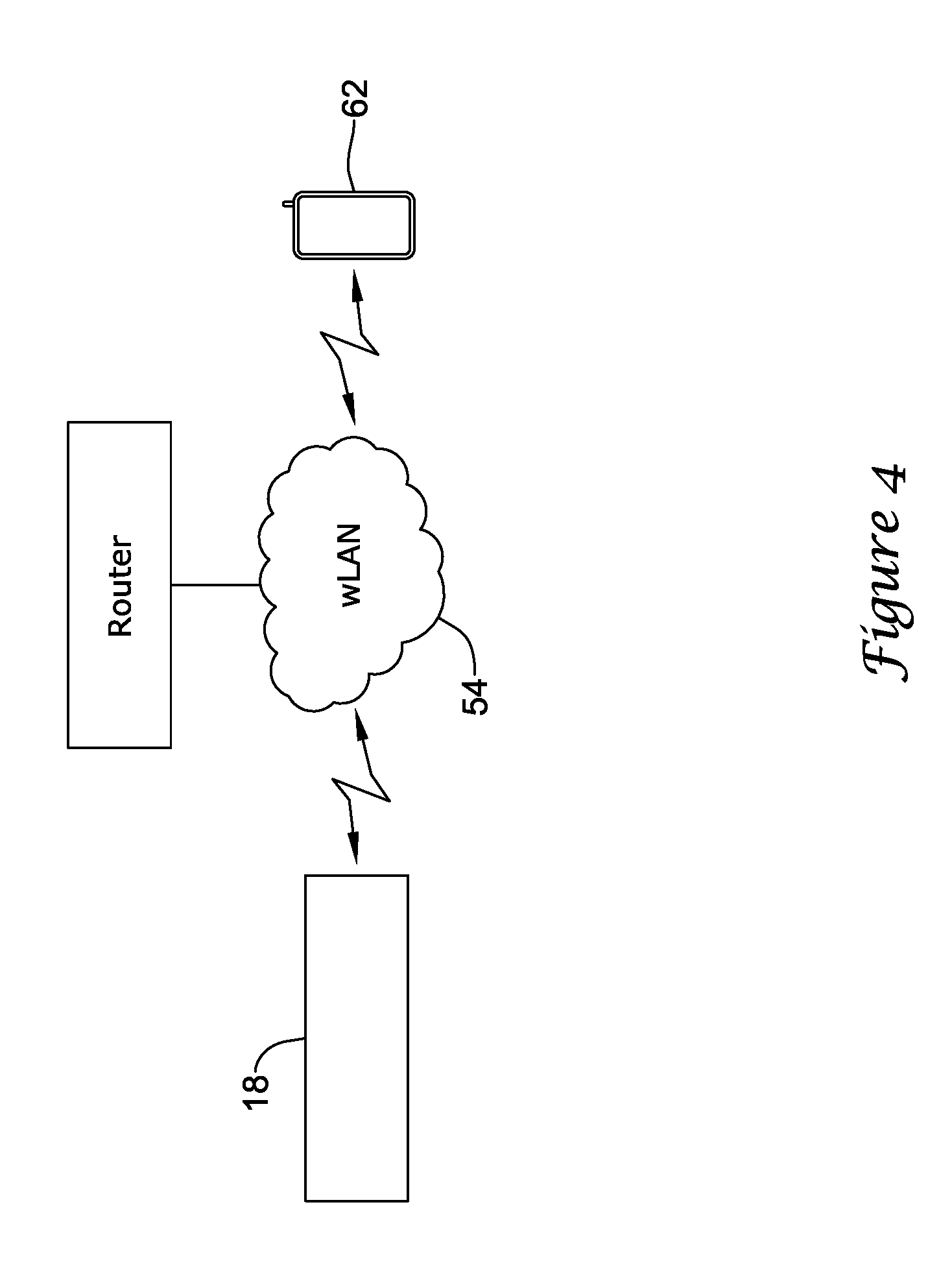
[0039] FIG. 4 is a schematic view of an illustrative HVAC controller 18 in communication with a user's mobile wireless device 62 over a building's local area network 54. The local area network 54 may be a wired or wireless network 54. In the example provided by FIG. 4, the local area network 54 is a wireless network. This is just one example. It will be generally understood that the HVAC controller 18 and the user's mobile wireless device 62 may communicate over a wired network if a gateway is provided that facilitates communication between the wired network and the wireless device 62. The mobile wireless device 62 may be any one of the mobile devices listed herein. For example, in some cases, the mobile wireless device 62 may be a smart phone with a wireless local area network capability or a key fob with a wireless local area network capability. A network enabled key fob may be provided to occupants or building users that do not have a mobile phone or other mobile device enrolled in the network such as for example, guests, minor children, housekeepers, pet sitters, maintenance workers and the like. As discussed above, both the HVAC controller 18 and the mobile wireless device 62 may be connected to and recognized by the local area network 54 through a unique identifier that has been assigned to each device connected to the network 54, including the HVAC controller 18 and the user's mobile wireless device 62. In some embodiments, the HVAC controller 18 may be programmed to detect whether or not a user's mobile wireless device 62 is connected to and recognized by the local area network 54.
[0040] In some cases, the HVAC controller 18 may be programmed to repeatedly broadcast a query on the local area network 54 requesting a response from a user's mobile wireless device 62. In some cases, the HVAC controller 18 may be configured to detect if the user's mobile wireless device 62 is currently connected to and recognized by the building's local area network using, at least in part, any number of different available protocols suitable for broadcasting a query and receiving a response over a wireless local area network. For example, the HVAC controller may be configured to detect if the user's mobile wireless device is currently connected to and recognized by the building's wireless local area network using a multitask DNS or link-local Multicast Name Resolution (LLMNR) algorithm, a zero configuration networking algorithm such as, for example Apple Inc.'s BONJOUR.TM. software, a Universal Plug and Play (UPnP) algorithm, and/or the like.
[0041] The mobile device 62 may be configured to provide a response to such a query from another device such as, for example, the HVAC controller 18. The mobile wireless device 62 may be configured to provide a response to the query from the HVAC controller 18 when the mobile wireless device 62 is within range and connected to and recognized by the building's wireless local area network. The mobile wireless device 62 will not provide a response to the query when the mobile wireless device 62 is not connected and/or not recognized by the local area network 54. In some cases, an application program code (i.e. app) stored in the memory of the mobile wireless device 62 may be used to enable the mobile wireless device 62 to respond to the query from the HVAC controller 18. The application program code (app) may be provided for downloading from the external web service hosted by the external web server to which the HVAC controller 18 may also be connected (see, for example, FIG. 2) or another external web service (e.g. ITUNES.RTM. or Google's App Store). The HVAC controller 18 may be programmed to interpret such a response from the mobile wireless device 62 as an indication of occupancy of the building.
[0042] In some cases, the mobile wireless device 62 need not response to every query received from the HVAC controller 18. Instead, the mobile wireless device 62 may only initially respond to a query from the HVAC controller 18 when it has entered the local area network 54. This may also be used to detect occupancy of the building. Upon leaving the local area network 54, the mobile wireless device 62 may be configure to send a message to the HVAC controller 18 indicating that it is no longer connected to the local area network 54. In some cases, this message may be sent via the external web server 66. The HVAC controller 18 may then respond by returning to an unoccupied mode of operation.
[0043] When the HVAC controller 18 detects that an occupant's mobile wireless device 62 is connected to and/or recognized by the local area network 54, the HVAC controller 18 may be further programmed to determine that the building is occupied. Upon determining that the building is occupied, the HVAC controller 18 may change at least one operational parameter setting of the HVAC system 4 (FIG. 1). For example, and in some cases, upon determining that the building is occupied, the HVAC controller 18 may change at least one operational parameter setting in accordance with an occupied mode stored in the memory 72 of the controller 18. In other cases, the HVAC controller 18 may be configured to associate the occupant's wireless mobile wireless device 62 with the occupant's user profile, and may be programmed to change at least one operational parameter setting in accordance with one or more user-selected settings associated with an occupied mode as defined by the occupant's user profile. In some cases, the occupant's user profile may be stored locally in the memory 72 of the HVAC controller 18. In other cases, upon detecting that a user's mobile wireless device 62 is connected to the wireless network 54, the HVAC controller 18 may be programmed to download at least a portion of the user's profile from an external web service hosting the user's profile.
[0044] The HVAC controller 18 may be programmed to continue to repeatedly broadcast a query on the local area network 54, and may continue to receive a response from the user's mobile wireless device 62 confirming that the user's mobile wireless device 62 is still connected to the wireless local area network 54 and that the building is still occupied. The HVAC controller 18 may continue to control, at least in part, one or more components of the HVAC system 4 in accordance with one or more predetermined settings associated with an occupied mode and/or according to one or more predetermined settings of an occupied mode associated with the occupant's user profile. As the building continues to be occupied, the HVAC controller 18 may continue to control the one or more HVAC components in accordance with a predetermined operating schedule or one or more additional modes. For example, if time passes and a sleep period of a programmed schedule of the HVAC controller 18 is entered, the HVAC controller 18 may control the one or more HVAC components of the HVAC system 4 in accordance with one or more predetermined operational settings associated with the sleep mode.
[0045] In some cases, the HVAC controller 18 may be further programmed to change at least one operational parameter setting of the HVAC system when the HVAC controller 18 no longer detects that the user's mobile wireless device 62 is connected to and/or recognized by the wireless local area network 54. For example, when the occupant leaves the building and the occupant's mobile wireless device 62 is out of range of the local area network 54, the occupant's mobile wireless device 62 will no longer respond to the query broadcasted over the local area network 54 by the HVAC controller 18. Before confirming that the user's mobile device 62 is no longer connected to and/or recognized by the network, the HVAC controller 18 may be programmed to send out a predetermined number of queries to the user's mobile device 62. If, after the predetermined number of queries, the HVAC controller 18 does not receive a response from the user's mobile device 62, the HVAC controller 18 may determine that the building is unoccupied. Upon determining that the building is unoccupied, the HVAC controller 18 may change at least one operational parameter setting of the HVAC system 4 in accordance with one or more predetermined settings associated with an unoccupied mode and/or according to one or more predetermined settings associated with an unoccupied mode according to the occupant's user profile. In some cases, the HVAC controller 18 may be configured to change at least the temperature set point and/or another operational parameter setting to a more energy efficient setting when the user's mobile device 62 is not connected to and/or recognized by the wireless local area network 54 and the building is unoccupied.
[0046] In some cases, more than one user's mobile devices 62 may be enrolled. When so provided, the HVAC controller 18 may be programmed to remain in an occupied mode when any of the user's mobile devices 62 remain connected to and/or recognized by the local area network 54. That is, the HVAC controller 18 may not enter an unoccupied mode until all of the user's mobile devices 62 are no longer connected to and/or recognized by the wireless local area network 54. Also, in some cases, the HVAC controller 18 may store a rank of various user mobile devices 62. When so provided, and when more than one user mobile devices are connected to and/or recognized by the wireless local area network 54, the HVAC controller 18 may control to the user profile that is associated with the particular user's mobile device 62 that is connected to and/or recognized by the wireless local area network 54 and has the highest rank.
[0047] When the building is unoccupied, the HVAC controller 18 may be programmed to continue to broadcast a query over the local area network 54 and wait for a response from a user's mobile device indicating that the building is occupied. If, after a predetermined period of time, the HVAC controller 18 continues to receive no response from a user's mobile device, the HVAC controller 18 may be programmed to determine that the building is unoccupied for an extended period of time. In some cases, for example, the HVAC controller 18 may be configured to determine that the building is unoccupied for an extended period of time when it does not receive any response from a user's mobile device 62 for a period of time of greater than 24 hours, 36 hours, 48 hours, or 72 hours. These are just examples. Upon determining that the building is unoccupied for an extended period of time, the HVAC controller 18 may change at least one operational parameter setting of the HVAC system 4 in accordance with a vacation mode or an extended away mode. The operational parameter settings associated with the vacation mode or the extended away mode may be predetermined by a user and in some cases associated with a user's profile, and may be a more energy efficient setting. The operational parameter settings for the extended away or vacation modes may be the same or more energy efficient than the operational parameter settings associated with the unoccupied mode.
[0048] The HVAC controller 18 may be configured to repeatedly transmit a query and wait for a response from a mobile wireless device enrolled in the network even when the HVAC controller 18 is operated in a vacation or extended away mode. When the occupant returns to the building and the HVAC controller 18 receives a response to a query, the HVAC controller 18 may determine that the building is again occupied and may change at least one operational parameter setting in accordance with an occupied mode, as described herein.
[0049] FIG. 5 is a flow chart of a method 120 for controlling an HVAC system according to an illustrative embodiment. The method includes an HVAC controller, such as HVAC controller 18, described herein, repeatedly transmitting queries for a mobile wireless device over a building's local area network (Block 150). In some cases, the mobile wireless device has been previously enrolled with the local area network and has been assigned a unique identifier that identifies the mobile wireless device each and every time it is connected to the network. The mobile wireless device may be programmed to response to such query from the HVAC controller 18. The HVAC controller 18 may receive one or more responses to its queries over the wireless local area network only when the mobile wireless device is within range, connected to and recognized by the local area network, indicating occupancy of the building (Block 160). When the controller 18 does not receive a response from the mobile wireless device, the HVAC controller 18 may determine that the building is unoccupied. Upon receiving one or more response from a mobile wireless device connected to and recognized by the local area network, the HVAC controller 18 may automatically change at least one operational parameter setting of the HVAC system (Block 170). When the HVAC controller 18 no longer receives a response from the mobile wireless device, the HVAC controller 18 may automatically change at least one operational parameter setting to a more energy efficient setting. In some cases, the operational parameter setting may include a temperature set point.
[0050] It will be generally understood that the system and method, as described herein, may also be used in conjunction with other methods and/or devices used to determine the occupancy status of a building.
[0051] Having thus described several illustrative embodiments of the present disclosure, those of skill in the art will readily appreciate that yet other embodiments may be made and used within the scope of the claims hereto attached. Numerous advantages of the disclosure covered by this document have been set forth in the foregoing description. It will be understood, however, that this disclosure is, in many respect, only illustrative. Changes may be made in details, particularly in matters of shape, size, and arrangement of parts without exceeding the scope of the disclosure. The disclosure's scope is, of course, defined in the language in which the appended claims are expressed
* * * * *
D00000
D00001
D00002
D00003
D00004
D00005
XML
uspto.report is an independent third-party trademark research tool that is not affiliated, endorsed, or sponsored by the United States Patent and Trademark Office (USPTO) or any other governmental organization. The information provided by uspto.report is based on publicly available data at the time of writing and is intended for informational purposes only.
While we strive to provide accurate and up-to-date information, we do not guarantee the accuracy, completeness, reliability, or suitability of the information displayed on this site. The use of this site is at your own risk. Any reliance you place on such information is therefore strictly at your own risk.
All official trademark data, including owner information, should be verified by visiting the official USPTO website at www.uspto.gov. This site is not intended to replace professional legal advice and should not be used as a substitute for consulting with a legal professional who is knowledgeable about trademark law.