Wall Mount Bracket For Outdoor Equipment
CROWLEY; William J.
U.S. patent application number 16/154934 was filed with the patent office on 2019-02-07 for wall mount bracket for outdoor equipment. The applicant listed for this patent is Quick-Sling, LLC. Invention is credited to William J. CROWLEY.
| Application Number | 20190041090 16/154934 |
| Document ID | / |
| Family ID | 55852278 |
| Filed Date | 2019-02-07 |


View All Diagrams
| United States Patent Application | 20190041090 |
| Kind Code | A1 |
| CROWLEY; William J. | February 7, 2019 |
WALL MOUNT BRACKET FOR OUTDOOR EQUIPMENT
Abstract
A wall mount bracket for HVAC Equipment such as a heat pump, AC condensing unit, and preferably the exterior condenser unit of a mini split system. The system can advantageously be used in colder climates to prevent equipment from freezing and keep equipment above the level of the snow, etc. The wall mounts herein employ an offset to space the unit away from the wall of the structure to provide clearance on the rear of the unit. The offset also allows the units to be mounted above the top of the foundation wall without disrupting the exterior siding of the structure.
| Inventors: | CROWLEY; William J.; (East Freetown, MA) | ||||||||||
| Applicant: |
|
||||||||||
|---|---|---|---|---|---|---|---|---|---|---|---|
| Family ID: | 55852278 | ||||||||||
| Appl. No.: | 16/154934 | ||||||||||
| Filed: | October 9, 2018 |
Related U.S. Patent Documents
| Application Number | Filing Date | Patent Number | ||
|---|---|---|---|---|
| 14928174 | Oct 30, 2015 | 10113769 | ||
| 16154934 | ||||
| 62072507 | Oct 30, 2014 | |||
| Current U.S. Class: | 1/1 |
| Current CPC Class: | F24F 13/32 20130101; F16M 13/02 20130101; E04G 5/062 20130101 |
| International Class: | F24F 13/32 20060101 F24F013/32; E04G 5/06 20060101 E04G005/06; F16M 13/02 20060101 F16M013/02 |
Claims
1. A method comprising: securing a first arm to an exterior side of a foundation; extending a second arm longitudinally from the first arm away from the exterior side such that the second arm extends longitudinally over a grade level; and positioning an electrically-powered HVAC item onto the second arm such that the electrically-powered HVAC item is spaced apart from the exterior side and from the grade level.
2. The method of claim 1, wherein the first arm is secured to the exterior side above the grade level.
3. The method of claim 1, wherein the first arm includes a first longitudinal portion, a second longitudinal portion, and a third longitudinal portion, wherein the first longitudinal portion is parallel to the third longitudinal portion, wherein the second longitudinal portion spans between the first longitudinal portion and the third longitudinal portion, wherein the first arm is secured to the exterior side via the first longitudinal portion.
4. The method of claim 3, wherein the second longitudinal portion is diagonal relative to the first longitudinal portion.
5. The method of claim 3, wherein the second longitudinal portion is diagonal relative to the exterior side.
6. The method of claim 1, wherein the second arm is L-shaped.
7. The method of claim 1, wherein the first arm is coupled to the second arm via a plate, wherein the plate has an inner angle, wherein the inner angle is obtuse.
8. The method of claim 1, wherein the second arm includes a top-hat shaped cross sectional portion extending longitudinally over the grade level.
9. The method of claim 1, wherein the second arm includes a first portion and a second portion, wherein the first portion extends longitudinally along a vertical plane, wherein the second portion extends longitudinally along a horizontal plane, and further comprising: securing the electrically-powered HVAC item to the first portion and the second portion.
10. The method of claim 1, further comprising: extending a third arm longitudinally from the first arm away from the grade level; securing a roof to the third arm such that the electrically-powered HVAC item is positioned between the roof and the grade level.
11. The method of claim 10, wherein the third arm includes a longitudinal portion distal to the first arm, wherein the longitudinal portion extends longitudinally over the grade level.
12. The method of claim 1, wherein the first arm is tubular.
13. The method of claim 1, wherein the first arm longitudinally extends away from the exterior side at an angle from about 15 degrees to about 75 degrees.
14. A method comprising: securing a first arm to an exterior side of a foundation, wherein the exterior side is positioned below a siding section; extending a second arm longitudinally from the first arm along the siding section away from the foundation and spaced apart from the siding section; and coupling a roof onto the second arm such that the roof is spaced apart from the siding section and a grade level such that a height is defined between the roof and the grade level.
15. The method of claim 14, wherein the second arm extends away from the grade level parallel to the first arm.
16. The method of claim 14, wherein the second arm extends away from the grade level parallel to the exterior side.
17. The method of claim 14, wherein the second arm extends away from the grade level parallel to the siding section.
18. The method of claim 14, wherein the first arm is secured to the exterior side above the grade level.
19. The method of claim 14, wherein the first arm is tubular.
20. The method of claim 14, wherein the first arm longitudinally extends away from the exterior side at an angle from about 15 degrees to about 75 degrees.
Description
CROSS REFERENCE TO RELATED APPLICATIONS
[0001] This application is a Continuation of a U.S. Utility application Ser. No. 14/928,174 filed 30 Oct. 2015, which claims a benefit of U.S. Provisional Application 62/072,507 filed Oct. 30, 2014, each of which is herein incorporated by reference for all purposes.
BACKGROUND
[0002] The present invention relates generally to a mounting bracket and, more particularly, to a wall mounted bracket for an outdoor appliance such as an outdoor component of a heating and/or cooling system. The bracket herein may advantageously be used in connection with a heating and/or cooling system such as the outdoor condensing unit of a split system, especially a compact or so-called mini split system, and will be described primarily by way of reference thereto. It will be recognized, however, that the present mounting system may be used for all manner of equipment including air conditioning condensers/compressors, electrical transformers, and so forth.
[0003] Mini split air handling systems such as air conditioners or heat pumps locate the compressor and condenser outside the house or other structure to be heated or cooled. Such systems eliminate the need for extensive duct work in the structure by using thin copper tubing to pump a refrigerant to wall mounted blowers inside the structure (ductless) or to compact duct units that allow the evaporator to be hidden while requiring minimal ductwork.
[0004] Commonly, the outdoor condensing units are set on a pad outside the structure, such as a poured concrete slab or a prefabricated pad. In addition to requiring significant site preparation, the use of slabs are commonly very low to the ground, e.g., a few inches above grade, making their use impractical in areas receiving significant snowfall or having a high water table. Units set on a slab or pad are also susceptible to weed/plant growth around the unit, accumulation of leaves, damage from mowers or weed trimmers, and so forth. The present disclosure contemplates a new and improved mounting apparatus and method which overcomes the above-referenced problems and others.
SUMMARY
[0005] A support apparatus for attaching equipment to a wall of a structure includes first and second of angled bracket arms configured to be mounted side by side in spaced apart relation. Each of the first and second angled bracket arms includes a lower portion configured to be attached to a foundation of the structure; an angled portion extending from the lower portion along a direction angled from an extending direction of the lower portion; and an upper portion extending from the angled portion along a direction generally parallel to the extending direction of the lower portion.
[0006] In one aspect, an equipment support arm is supported on each of the first and second angled bracket arms, the equipment support arm including a horizontal member secured at a generally right angle to a vertical member, wherein the vertical member is removably attached to the upper portion of a respective one of the first and second angled bracket arms.
[0007] In another aspect, an upper support member is attached to the upper portion, the upper support member including a proximal portion extending from the upper portion along a direction parallel to an extending direction of the upper portion and a distal portion extending from the proximal portion along a direction angled from an extending direction of the proximal portion.
DESCRIPTION OF DRAWINGS
[0008] The invention may take form in various components and arrangements of components, and in various steps and arrangements of steps. The drawings are only for purposes of illustrating preferred embodiments and are not to be construed as limiting the invention.
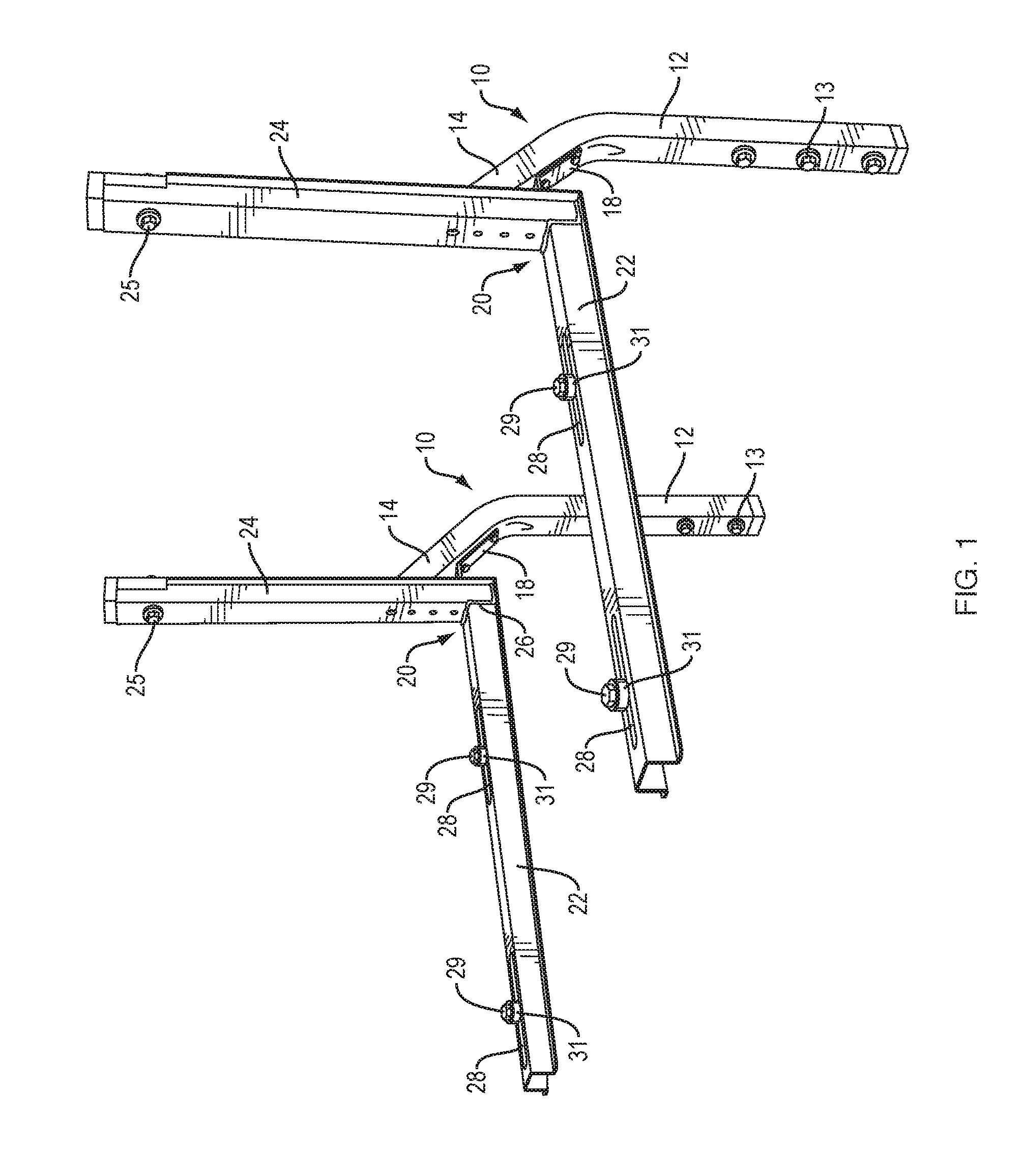
[0009] FIG. 1 is an image of a first exemplary wall mounting bracket embodiment, taken generally from the right side and the front.
[0010] FIG. 2 is an image showing an enlarged, fragmentary view of a second exemplary wall mounting bracket embodiment, taken generally from the left side.
[0011] FIG. 3 is an image showing the embodiment appearing in FIG. 2, taken generally from the front.
[0012] FIG. 4 is an enlarged, fragmentary view of the horizontal mounting arm showing the elongate hardware slot and exemplary fastener hardware with vibration isolator or dampener.
[0013] FIG. 5 is a partially exploded view of the embodiment appearing in FIG. 1.
[0014] FIG. 6 is an image showing a perspective view of a third exemplary wall mounting bracket system herein, configured with upper mounting arms in place of lower mounting arms, taken generally from the front and right side.
[0015] FIG. 7 is a fragmentary side view of a similar bracket embodiment configured for use with the upper mounting arms.
[0016] FIG. 8 is a perspective view of the embodiment appearing in FIG. 6, with the upper arms removed and illustrating the adapters.
[0017] FIG. 9 is a perspective view of the upper mounting arms appearing in FIG. 6 removed from the wall mounted portion, taken generally from the bottom and side.
[0018] FIG. 10 is a perspective view of the upper mounting arms appearing in FIG. 9 taken generally from the front and bottom.
[0019] FIG. 11 is a perspective view of a further embodiment of the present invention including a roof supported over the wall mounting bracket.
[0020] FIG. 12 is an enlarged front view of the region 12 appearing in FIG. 11.
[0021] FIG. 13 shows an exemplary installation on an exterior wall of a building.
[0022] FIG. 14 is a front elevational view of an exemplary wall mounting system herein.
[0023] FIG. 15 is a side elevational view of the wall mounting system appearing in FIG. 14.
[0024] FIG. 16 is a top plan view of the wall mounting system appearing in FIG. 14.
[0025] FIG. 17 is an exploded view of the wall mounting system appearing in FIG. 14.
[0026] FIG. 18 depicts a preferred cross-sectional shape of the horizontal and vertical components of the L-shaped lower mounting arms.
DETAILED DESCRIPTION OF PREFERRED EMBODIMENTS
[0027] Referring now to the drawings, FIGS. 1-5 and 13-17 illustrate a wall mounted bracket system comprising a pair of angled bracket arms 10 mounted side by side and spaced apart any desired width D, which may be selected to accommodate the width of the equipment to be mounted. Although the present invention is described by way of reference to the preferred embodiment wherein two arms 10 are used, it will be recognized that any other number, such as 3, 4, 5, 6, 7, 8, etc., of arms 10 may be employed. The dimensions given in FIGS. 15 and 16 are exemplary only and are not intended to be limiting.
[0028] The bracket arms 10 are, for example, 2'' or 13/4'' square tubing, preferably steel, although bracket arms formed of other metal or metal alloy are also contemplated. Each bracket arm 10 includes a lower portion 12 for attaching to a foundation wall 11 and an angled portion 14 angled away from the wall. The angle A may be any angle in the range of from about 15 degrees to about 75 degrees and is preferably about 45 degrees). The arm 10 further includes an upper portion 16 which extends in a direction that is generally parallel to the extending direction of the lower portion, i.e., generally vertically from the upper end of the angled portion 14 and is spaced away from wall.
[0029] The bracket arms 10 may be formed by bending the metal tubing. When the lower portions 12 are secured to the exterior side of a foundation wall, the offset portions 14 and 16 can extend above the top of the foundation wall without the need to putting holes in the siding material of the building. The spacing also allows the units to be mounted in accordance with mandatory clearance requirements between the equipment and the building wall, provides room for piping and access for servicing the mounted equipment.
[0030] The lower portion 12 is bolted or anchored to the wall with threaded fasteners 13. A rigid plate, e.g., metal and preferably steel plate 18 extends along the lower or outward facing surface of the angled portion 14 and in certain embodiments includes a bend 19 to define a proximal portion 18p extending along and secured to the angled portion 14 and a distal portion 18d extending horizontally a distance from the proximal portion. The distal end of the plate 18d extends a distance sufficient to form a rest or shelf for a proximal end of a lower support arm 20. In certain embodiments, the lower support arms 20 are generally L-shaped and may be formed of bent or roll-formed sheet metal forming a channel with axial extending flanges on either side, i.e., having a generally top-hat shaped cross section.
[0031] As best seen in FIG. 18, the support arm vertical and horizontal members 22, 24 may be formed of a stock material having parallel axially extending side walls 62 and an axially extending web 64 extending between the parallel axially extending side walls 62, the parallel axially extending side walls 62 and the axially extending web 64 cooperating to define a channel 60. In the illustrated preferred embodiment, each of the support arm vertical and horizontal members 22, 24 further include axial, outwardly extending flanges 66 on the ends each of the parallel axially extending side walls 62 opposite the web 64, wherein the parallel axially extending side walls 62, axially extending web 64, and outwardly extending axial flanges 66 cooperate to define a structure having a generally top-hat shaped cross sectional shape.
[0032] Each lower support arm 20 has a horizontal member 22 and a vertical member 24 secured at right angles. The lower support arm vertical member 24 has a notch 26 cut out to receive the proximal end of the horizontal member 22, which extends into the channel defined by the vertical member and rests on the protruding, distal end portion of the bent plate 18. The proximal end of the plate 18 may be secured to the angled portion 14 via bolts, or, may be permanently secured thereto, e.g., via welding. In the illustrated preferred embodiment, the horizontal member 22 and the vertical member 24 are secured to each other by a welded joint.
[0033] Elongated openings 28 are provided in the upper surface of the horizontal member 22 to accommodate mounting hardware such as bolts 29 to attach the condensing unit to the arms 22. In the preferred embodiments, vibration absorbing couplings 31 are disposed between the condensing unit (not shown) and the arm horizontal member 22 to absorb vibration and noise emanating from the condenser to prevent or reduce amplification of such noise and vibration by the bracket arms 10 and to prevent or reduce transmission of such noise or vibration to the house of other structure to which the bracket arms 10 are mounted.
[0034] The vibration absorbing coupling members 31 may be formed of a material which is resilient, flexible, compressible, deformable, compliant, and/or elastic, and is preferably a polymeric material. Most preferably, the coupling member 31 is formed of an elastomeric material, such as a synthetic or natural elastomeric or rubber material. Exemplary elastomeric materials which may be used in making the coupling member include, for example, polyurethane, polyisoprene, polybutadiene, neoprene, butadiene-acrylonitrile copolymers, ethylene-butadiene block copolymers, ethylene-propylene based copolymers, natural rubber, polychloroprene rubber, polyisoprene-isobutylene copolymers, silicone rubber, styrene-acrylonitrile copolymers, styrene-butadiene copolymers, styrene-isoprene copolymers, styrene-maleic anhydride copolymers, fluoroelastomers, polyolefins, and so forth.
[0035] The vertical members 24 are bolted to the upper portion 16 of the bracket arms with threaded fasteners 25. The channel shape of the support arms 20 defines a channel that is sized to receive the upper portion 16 of the bracket arm 10.
[0036] Although the bracket arms 10 can be adapted for use with any wall of a structure where it is desired to mount equipment, as best seen in FIG. 13, the bracket arms 10 support arms 20 are advantageous for supporting equipment E above ground or grade level G, and are particularly advantageous for supporting the equipment E configured for secure attachment to an exterior surface of a foundation wall 11 of a structure or building B without the need to penetrate, remove, or otherwise interfere without exterior siding or wall cladding S applied to the walls of the structure B above the level of the foundation 11. In addition, the horizontal offset 0 between the lower portion 12 and the upper offset portion 16 enables the equipment E to be mounted to provide a clearance distance C between the back of the equipment E and the wall of the structure B in accordance with minimum clearance distances as specified by building codes or other regulations.
[0037] Referring now to FIGS. 6-10 (and continued reference to FIGS. 1-5), upper support arms 30 can be attached to the bracket arms 10, either in addition to or as an alternative to the lower support arms 20. The upper support arms 30 include a vertical portion 32 and an angled portion 34. In certain embodiments, the angled portion extends generally horizontally, e.g., therein the angled portion 34 is configured to support equipment. In other embodiments, the angled portion may be sloped relative to horizontal, e.g., wherein the angled portion 34 is configured to support a roof over equipment beneath the roof. The angles portion 34 includes a plurality of elongated openings 35, similar to the elongated openings 28.
[0038] An adapter 36 is secured in the open upper end of the bracket upper portion 16. The adapter 36 may be formed of a segment of steel tubing having an outer diameter that is equal to the inner diameter of the bracket arm 10 and the upper support arm 30. For example, in the case of a bracket arm 10 and upper support arm 30 formed of square tubing having an outer diameter of 13/4 inches and an inner diameter of 11/4 inches, the adapter is formed of formed of square steel tubing having an outer diameter of 11/4 inches. Other diameter tubing materials are contemplated. The adapter can be bolted in place with threaded fasteners 38.
[0039] The upper support arms 30 each comprise an inverted L-shaped piece of tubing wherein the lower end is received over the protruding portion of the adapter 36 and bolted in place with the threaded fasteners 38. The upper arms 30 may be used to support a mini-split condenser or other piece of equipment at a higher elevation than is possible with the lower support arms 20. Alternatively, the upper support arms 30 could be configured to support a roof or canopy over equipment located between the arms 10.
[0040] The upper support arms 30 could support a variety of purposes, as follows:
Method 1:
[0041] In method 1, the device is used without the lower support arms 20 and the equipment to be mounted is mounted on the upper support arms.
Method 2:
[0042] In method 2, the device is used without the lower support arms 20 and the equipment to be mounted is mounted on the ground, e.g., on a concrete slab, prefabricated pad, stand, etc. The upper arms 30 support a roof or canopy over the equipment beneath it.
Method 3:
[0043] In method 3, the device is used with the lower support arms 20 and the equipment to be mounted is mounted on the lower support arms. The upper arms 30 support a roof or canopy over the equipment beneath it.
Method 4:
[0044] In method 4, the device is used with the lower support arms 20. A first piece of equipment to be mounted is mounted on the lower support arms and a second piece of equipment is mounted on the upper support arms.
[0045] Referring now to FIGS. 11 and 12, there is shown a further embodiment wherein a roof support member 40 is attached to the offset portion 16 with fasteners 48. Advantageously, the roof support members 40 are secured to the inward facing surface of the respective offset portions.
[0046] Although the embodiment appearing in FIGS. 11 and 12 is shown with the lower arms 20 attached to the bracket arms 10, in alternative embodiments the lower arms 20 can be omitted, e.g., wherein the roof support members are provided to support a roof 50 over equipment on the ground, a pad, slab, or stand beneath the roof 50.
[0047] Each roof support member 40 includes a vertical portion 42 and a roof support portion 44. The lower end 46 of the roof support member 40 is secured to the offset portion 16 via bolts or other fasteners 48. In the illustrated embodiment, the transition between the vertical portion 42 and the roof support portion 44 is a radiused bend 43, although a fastened joint e.g., a welded joint, between the portions 42 and 44 is also contemplated. In the embodiment shown the roof support portion 44 is angled downward by an angle R to allow snow and debris to slide off the roof 50. In alternative embodiments, a generally horizontal roof may be provided. In certain embodiments one or more transverse support members 60 are provided, which extend between the roof support portions 44 to support the roof and prevent the roof member 50 from sagging. The roof 50 may be formed from any rigid sheet material, including without limitation wood, metal, plastic, and so forth. In certain embodiments, the roof member 50 is formed of twin walled polycarbonate sheet material.
[0048] Each roof support member 40 may be a unitary structure or may comprise two or more segments attached together. In the illustrated embodiment, the roof support member 40 includes a lower straight member 52 and an upper angled member 54. In this manner, a modular system can be provided wherein straight members 52 of different lengths can be provided wherein the length of the straight members 52 can be selected to support the roof 50 a desired or appropriate height.
[0049] The attachment joint between the straight member 52 and the angled member 54 appears in FIG. 12 and includes an adapter 56 telescopically received within each of the abutting ends of the adjoining lower straight member 52 and upper angled member 54, and secured in position with bolts or other threaded fasteners 58.
[0050] The invention has been described with reference to the preferred embodiment. Modifications and alterations will occur to others upon a reading and understanding of the preceding detailed description. It is intended that the invention be construed as including all such modifications and alterations insofar as they come within the scope of the appended claims or the equivalents thereof.
* * * * *
D00000
D00001
D00002
D00003
D00004
D00005
D00006
D00007
D00008
D00009
D00010
D00011
D00012

D00013

D00014

D00015

XML
uspto.report is an independent third-party trademark research tool that is not affiliated, endorsed, or sponsored by the United States Patent and Trademark Office (USPTO) or any other governmental organization. The information provided by uspto.report is based on publicly available data at the time of writing and is intended for informational purposes only.
While we strive to provide accurate and up-to-date information, we do not guarantee the accuracy, completeness, reliability, or suitability of the information displayed on this site. The use of this site is at your own risk. Any reliance you place on such information is therefore strictly at your own risk.
All official trademark data, including owner information, should be verified by visiting the official USPTO website at www.uspto.gov. This site is not intended to replace professional legal advice and should not be used as a substitute for consulting with a legal professional who is knowledgeable about trademark law.