Shut-off Member For A Fluid Valve, And Method For Producing A Shut-off Member
Mayer; Juergen ; et al.
U.S. patent application number 16/047277 was filed with the patent office on 2019-02-07 for shut-off member for a fluid valve, and method for producing a shut-off member. This patent application is currently assigned to GEMUE Gebr. Mueller Apparatebau GmbH & Co. Kommanditgesellschaft. The applicant listed for this patent is GEMUE Gebr. Mueller Apparatebau GmbH & Co. Kommanditgesellschaft. Invention is credited to Klaus Frankenbach, Juergen Mayer.
| Application Number | 20190040964 16/047277 |
| Document ID | / |
| Family ID | 63108468 |
| Filed Date | 2019-02-07 |


| United States Patent Application | 20190040964 |
| Kind Code | A1 |
| Mayer; Juergen ; et al. | February 7, 2019 |
SHUT-OFF MEMBER FOR A FLUID VALVE, AND METHOD FOR PRODUCING A SHUT-OFF MEMBER
Abstract
A shut-off member for a fluid valve is proposed. The shut-off member includes a blind hole that is made in the shut-off member, the blind hole leading from a dorsal side into a ventral portion; an electronic data carrier which is arranged in a base region of the blind hole; and a casting compound that is introduced into the blind hole and that fixes the electronic data carrier to the shut-off member.
| Inventors: | Mayer; Juergen; (Schwaebisch Hall, DE) ; Frankenbach; Klaus; (Forchtenberg-Schleierhof, DE) | ||||||||||
| Applicant: |
|
||||||||||
|---|---|---|---|---|---|---|---|---|---|---|---|
| Assignee: | GEMUE Gebr. Mueller Apparatebau
GmbH & Co. Kommanditgesellschaft Ingelfingen DE |
||||||||||
| Family ID: | 63108468 | ||||||||||
| Appl. No.: | 16/047277 | ||||||||||
| Filed: | July 27, 2018 |
| Current U.S. Class: | 1/1 |
| Current CPC Class: | F16K 7/14 20130101; F16K 37/0075 20130101; B23P 15/001 20130101; F16K 37/0041 20130101 |
| International Class: | F16K 7/14 20060101 F16K007/14; F16K 37/00 20060101 F16K037/00; B23P 15/00 20060101 B23P015/00 |
Foreign Application Data
| Date | Code | Application Number |
|---|---|---|
| Aug 7, 2017 | DE | 102017117910.0 |
Claims
1. Shut-off member for a fluid valve, the shut-off member comprising: a blind hole that is made in the shut-off member, the blind hole leading from a dorsal side into a ventral portion; an electronic data carrier which is arranged in a base region of the blind hole; and a casting compound that is introduced into the blind hole and that fixes the electronic data carrier to the shut-off member.
2. Shut-off member according to claim 1, wherein the blind hole comprises an undercut in the base region, wherein the casting compound engages in an interlocking manner in the undercut, and wherein the casting compound and the electronic data carrier are fixed to one another in an interlocking manner.
3. Shut-off member according to claim 1, wherein the blind hole comprises an internal thread that is arranged between an opening of the blind hole and the base region of the blind hole, in order to arrange a valve stem.
4. Shut-off member according to claim 1, wherein the base region of the blind hole comprises a base surface that is normal to the longitudinal axis of the blind hole.
5. Shut-off member according to claim 4, wherein the electronic data carrier is discoid, and wherein a disc surface of the electronic data carrier is oriented in a plane approximately in parallel with the base surface.
6. Shut-off member according to claim 4, wherein the electronic data carrier rests on the base surface.
7. Shut-off member according to claim 1, wherein a seat portion of the ventral portion is arranged radially outside the blind hole or outside an imaginary extension of the blind hole.
8. Shut-off member according to claim 1, wherein the material thickness of the shut-off member between the base region of the blind hole and a distal outer surface does not exceed a value of 3 mm.
9. Shut-off member according to claim 1, wherein an RFID chip (RFID=radio frequency identification) is provided as the electronic data carrier.
10. Shut-off member according to claim 1, wherein the shut-off member is substantially rotationally symmetrical.
11. Method for producing a shut-off member for a fluid valve, the method comprising: making a blind hole in the shut-off member, wherein the blind hole leads from a dorsal side into a ventral portion; arranging an electronic data carrier in a base region of the blind hole; and introducing a casting compound into the blind hole, wherein the casting compound fixes the electronic data carrier to the shut-off member.
12. (canceled)
Description
BACKGROUND OF THE INVENTION
[0001] The invention relates to a shut-off member for a fluid valve, and to a method for producing a shut-off member.
[0002] Shut-off members for fluid valves may be in a plurality of shapes and are adapted to the particular intended use or valve type. In particular, what are referred to as plug shut-off members or plug diaphragms are known. By way of example, reference is made to DE 10 2013 215 294 A1.
[0003] Furthermore, electronic data carriers, in particular RFID transponders, are known, the identifier of which can be read out in a contactless manner using a reader. WO 2015/010810 A1 for example discloses a membrane in which an electronic data carrier is arranged in a tab protruding from the membrane.
SUMMARY OF THE INVENTION
[0004] The object of the invention can therefore be considered that of fixing an electronic data carrier to a shut-off member.
[0005] The object of the invention is achieved by a shut-off member according to claim 1 and by a method for producing a shut-off member according to an independent claim.
[0006] According to a first aspect, a shut-off member for a fluid valve is proposed. The shut-off member comprises: a blind hole that is made in the shut-off member, the blind hole leading from a dorsal side into a ventral portion, to the surface of which a process fluid is applied during operation of the fluid valve; an electronic data carrier which is arranged in a base region of the blind hole; and a casting compound that is introduced into the blind hole and that fixes the electronic data carrier to the shut-off member.
[0007] The electronic data carrier is advantageously introduced from a rear side, i.e. the dorsal side of the shut-off member, as a result of which contact with the process fluid can be precluded during normal operation. In order to read out the electronic data carrier, a reader is brought towards the distal end of the ventral portion, and an identifier stored on the electronic data carrier is read out by the reader.
[0008] A further advantage of the proposed shut-off member is that the electronic data carrier is at a location that is different from a fastening region of the shut-off member. This isolation is advantageous in particular in the case of a rotationally symmetrical shut-off member that can be arranged in the fluid valve in any desired rotational position.
[0009] An advantageous embodiment is characterized in that the blind hole comprises an undercut in the base region, the casting compound engaging in an interlocking manner in the undercut, and the casting compound and the electronic data carrier being fixed to one another in an interlocking manner.
[0010] As a result, the electronic data carrier is fixed to the shut-off member in a simple manner. Interlocking fixing is advantageous in particular when the material (for example PTFE) in the base region has low adhesive force.
[0011] An advantageous embodiment is characterized in that the blind hole comprises an internal thread that is arranged between an opening of the blind hole and the base region of the blind hole, in order to arrange a valve stem. During operation of the fluid valve, the valve stem is screwed into the internal thread and moves the central portion of the shut-off member, by means of a drive. At the same time, the electronic data carrier is protected from damage, in the blind hole, by means of the casting compound.
[0012] An advantageous embodiment is characterized in that the base region of the blind hole comprises a base surface that is normal to the longitudinal axis of the blind hole. This advantageously makes it easier to arrange and install the electronic data carrier. At the same time, this improves the readout of the electronic data carrier through the ventral portion.
[0013] An advantageous embodiment is characterized in that the electronic data carrier is discoid, a disc surface of the electronic data carrier being oriented in a plane approximately in parallel with the base surface. This makes it possible to arrange the electronic data carrier in a space-saving manner.
[0014] An advantageous embodiment is characterized in that the electronic data carrier rests on the base surface. This improves the wireless readout of the electronic data carrier through the ventral portion.
[0015] An advantageous embodiment is characterized in that a seat portion of the ventral portion is arranged radially outside the blind hole or outside an imaginary extension of the blind hole. Since the base of the blind hole is brought as close as possible to an outer surface of the ventral portion, arranging the seat portion radially on the outside ensures mechanical stability of the shut-off member.
[0016] An advantageous embodiment is characterized in that the material thickness of the shut-off member between the base region of the blind hole and a distal outer surface does not exceed a value of 3 mm, in particular a value of 2 mm. The material thickness ensures reliable readout of the electronic data carrier.
[0017] An advantageous embodiment is characterized in that an RFID chip (RFID=radio frequency identification) is provided as the electronic data carrier.
[0018] An advantageous embodiment is characterized in that the shut-off member is substantially rotationally symmetrical.
[0019] A second aspect relates to a method for producing a shut-off member for a fluid valve. The method comprises: making a blind hole in the shut-off member, the blind hole leading from a dorsal side into a ventral portion; arranging an electronic data carrier in a base region of the blind hole; and introducing a casting compound into the blind hole, the casting compound fixing the electronic data carrier to the shut-off member.
BRIEF DESCRIPTION OF THE DRAWINGS
[0020] Further features and advantages of the invention are also found in the following description of embodiments shown in the drawings. In the drawings:
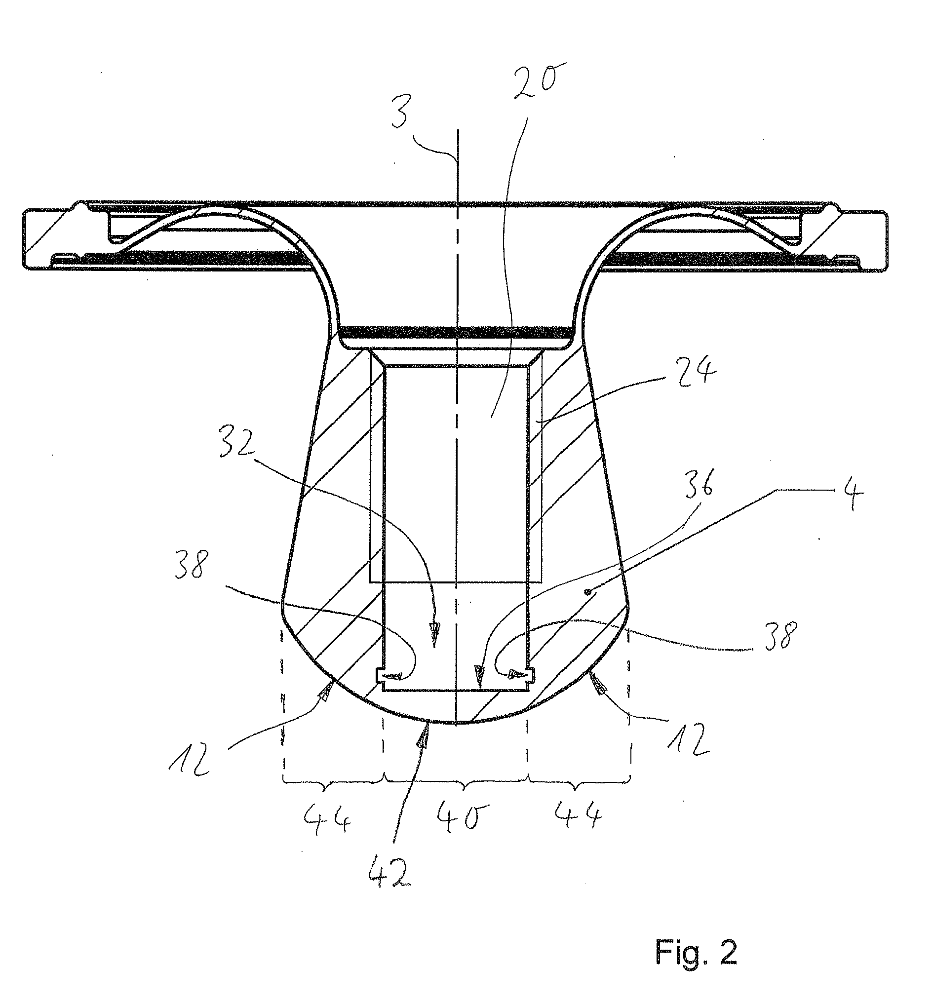
[0021] FIGS. 1 and 2 are schematic cross sections of a shut-off member; and
[0022] FIG. 3 is a schematic flow diagram.
DETAILED DESCRIPTION
[0023] FIG. 1 is a schematic cross section of a shut-off member 2. The shut-off member 2 is designed so as to be substantially rotationally symmetrical with respect to an axis of rotation 3. The shut-off member 2 can also be referred to as a plug diaphragm. The following description can of course also be transferred to differently designed shut-off members such as membranes or valve lifters. A ventral portion 4 of the shut-off member 2 is intended to be arranged in the direction of a fluid-conducting region 14 of a fluid valve. A dorsal portion 6 is intended to be arranged in the direction of a non-fluid-conducting region 16 of the fluid valve.
[0024] The dorsal portion 6 comprises a membrane portion 8 that transitions, radially outwardly, into a fastening portion 10. The fastening portion 10 is intended to be clamped for example between a valve body and an intermediate part of the fluid valve. Radially inwardly, the ventral portion 4 adjoins the membrane portion 8. In the distal direction, the ventral portion 4 increases in diameter and subsequently transitions into a dome region that comprises a seat region 12. The seat region 12 is used for installation on a valve seat.
[0025] Proceeding from the region 16, i.e. proceeding from the dorsal side of the shut-off member 2, a blind hole 20 extends along the axis of rotation 3 and into the ventral portion 4. Proceeding from an opening 22 of the blind hole 20, an internal thread 24 is milled into the wall of the blind hole. An external thread of a valve stem (not shown) of the fluid valve, which external thread corresponds to the internal thread 24, can be screwed into the internal thread 24. The valve stem, which is driven by a drive of the fluid valve, moves the ventral portion 4 axially in order to open and close a fluid channel. The membrane portion 8 allows for the above-mentioned movement and ensures separation of the regions 14 and 16.
[0026] An electronic data carrier 30 is arranged in a base region 32 of the blind hole 20 and is fixed to the shut-off member 2 by means of a casting compound 34 introduced into the blind hole. The electronic data carrier 30 is an RFID chip (RFID=radio frequency identification) and can also be referred to as a transponder. An identifier that is individual to the shut-off member 2 is stored on the electronic data carrier 30, which identifier is read out by means of a reader that is brought into the vicinity of the electronic data carrier 30. It is then possible, using said individual identifier, to monitor the shut-off member 2 even during production, and also in a facility belonging to the client/user.
[0027] The electronic data carrier 30 is for example discoid and may for example be rectangular or circular in plan view. A disc surface of the electronic data carrier 30 is arranged so as to be approximately in parallel with a base surface 36 of the blind hole 20. The base surface 36 is a plane that extends normally to the axis of rotation 3 of the blind hole 20. In the present example, the electronic data carrier 30 rests in a planar manner on the base surface 36 and is completely surrounded by the casting compound 34 in the dorsal direction. When hardened, the casting compound 34 engages in an undercut 38 of the blind hole 20, surrounds the electronic data carrier 30 at least in portions, and thus fixes the electronic data carrier 30 relative to the shut-off member 2 in an interlocking manner. This principle of the interlocking connection is advantageous in particular when the ventral portion 4 is made of polytetrafluoroethylene (PTFE), since polytetrafluoroethylene has a reduced surface tension.
[0028] The casting compound 34 comprises epoxy resin for example, which is metered into the blind hole 20 after the electronic data carrier 30 has been arranged. The casting compound 34 that is metered in is then hardened, for a hardening duration of at least 10 minutes, in particular at least 15 minutes, in a furnace at a hardening temperature of over 100.degree. C., in particular over 130.degree. C. In a further embodiment, the casting compound is furnace-hardened at 150.degree. C. for one hour. The electronic data carrier 30 is thus fixed in the blind hole 20 by means of the casting compound 34. The casting compound 34 is preferably not electrically conductive and not magnetizable, and therefore wireless communication with the electronic data carrier 30 is not disrupted.
[0029] An imaginary extension 39 of the blind hole 20 that proceeds from the base surface 36 is located radially within a seat region 12. The structural isolation of the two regions prevents deformation or damage in a central region 40 of the shut-off member 2. The material thickness of the shut-off member 2 between the base surface 36 of the blind hole 20 and a distal outer surface 42 of the central region 40 is in a range of between 3 mm and 0.5 mm, in particular in a range of between 2 mm and 1 mm, as a result of which the readout of the electronic data carrier 30 through the central region 40 is improved.
[0030] FIG. 2 is a schematic cross section through the shut-off member 2, the electronic data carrier 30 and the casting compound 34 not being shown. A lateral region 44 that surrounds the central region 40 adjoins radially outside the central region 40. The base region 32 comprises the base surface 36 and the undercut 38.
[0031] FIG. 3 is a schematic flow diagram illustrating the production of the shut-off member 2 from FIG. 1. In a first step 302, the blind hole is made in the shut-off member. Step 302 comprises, for example, drilling the blind hole and subsequently producing the planar base surface 36. In a step 304, the electronic data carrier is arranged in the base region of the blind hole. For example, the electronic data carrier is preferably placed centrally on the base surface 36. In a step 306, the casting compound is introduced into the blind hole and in particular into the base region of the blind hole. The step 306 also comprises hardening the casting compound in the blind hole. In particular, the casting compound flows into the undercut, simultaneously surrounds the electronic data carrier, and, after hardening, fixes the electronic data carrier in the blind hole, and thus to the shut-off member, in an interlocking manner.
* * * * *
D00000
D00001
D00002
D00003
XML
uspto.report is an independent third-party trademark research tool that is not affiliated, endorsed, or sponsored by the United States Patent and Trademark Office (USPTO) or any other governmental organization. The information provided by uspto.report is based on publicly available data at the time of writing and is intended for informational purposes only.
While we strive to provide accurate and up-to-date information, we do not guarantee the accuracy, completeness, reliability, or suitability of the information displayed on this site. The use of this site is at your own risk. Any reliance you place on such information is therefore strictly at your own risk.
All official trademark data, including owner information, should be verified by visiting the official USPTO website at www.uspto.gov. This site is not intended to replace professional legal advice and should not be used as a substitute for consulting with a legal professional who is knowledgeable about trademark law.