Clutch Actuation Mechanism
TIEMEYER; Sebastian ; et al.
U.S. patent application number 16/155253 was filed with the patent office on 2019-02-07 for clutch actuation mechanism. This patent application is currently assigned to HELLA GMBH & CO. KGAA. The applicant listed for this patent is HELLA GMBH & CO. KGAA. Invention is credited to Frank BEWERMEYER, Hagen MUELLER, Sebastian TIEMEYER.
| Application Number | 20190040918 16/155253 |
| Document ID | / |
| Family ID | 55701849 |
| Filed Date | 2019-02-07 |


View All Diagrams
| United States Patent Application | 20190040918 |
| Kind Code | A1 |
| TIEMEYER; Sebastian ; et al. | February 7, 2019 |
CLUTCH ACTUATION MECHANISM
Abstract
A clutch actuation mechanism for actuating a clutch operator of a spring loaded friction clutch having at least a motor driven rotary disc for being connected to the clutch operator enables to operate the motor with an essentially constant and reduced torque, if a pin is attached to the disc with an offset from the disc's rotary axis, and if a lever has a curved contacting surface and if a spring forces the lever with its contacting surface against the pin to thereby provide an additional torque to the disc. Thus, the pin travels over the contacting surface when the disc rotates to open or close the spring loaded clutch via the clutch operator and the curvature enables to adapt the torque provided by the spring to the torque required to compensate for the clutch spring.
| Inventors: | TIEMEYER; Sebastian; (Dortmund, DE) ; MUELLER; Hagen; (Bad Wuennenberg - Fuerstenberg, DE) ; BEWERMEYER; Frank; (Bueren, DE) | ||||||||||
| Applicant: |
|
||||||||||
|---|---|---|---|---|---|---|---|---|---|---|---|
| Assignee: | HELLA GMBH & CO. KGAA Lippstadt DE |
||||||||||
| Family ID: | 55701849 | ||||||||||
| Appl. No.: | 16/155253 | ||||||||||
| Filed: | October 9, 2018 |
Related U.S. Patent Documents
| Application Number | Filing Date | Patent Number | ||
|---|---|---|---|---|
| PCT/EP2017/057955 | Apr 4, 2017 | |||
| 16155253 | ||||
| Current U.S. Class: | 1/1 |
| Current CPC Class: | F16D 2300/18 20130101; F16D 28/00 20130101; F16D 13/752 20130101; F16D 2023/123 20130101; F16D 23/146 20130101; F16D 2023/126 20130101; F16D 23/12 20130101; F16D 27/112 20130101 |
| International Class: | F16D 23/14 20060101 F16D023/14; F16D 28/00 20060101 F16D028/00; F16D 13/75 20060101 F16D013/75; F16D 27/112 20060101 F16D027/112 |
Foreign Application Data
| Date | Code | Application Number |
|---|---|---|
| Apr 8, 2016 | EP | 16164473.7 |
Claims
1. A clutch actuation mechanism for actuating a clutch operator of a spring loaded friction clutch, the clutch actuation mechanism comprising: at least one a rotary disc connectable to the clutch operator, the at least one rotary disc being supported by a radial bearing defining the at least one rotary disc's rotary axis and being coupled to a motor to provide a first torque to the at least one rotary disc; a pin attached to the at least one rotary disc with an offset from the disc's rotary axis; a lever having a contacting surface and being pivotally supported to pivot around a lever's pivot axis, wherein the pivot axis and the rotary axis are substantially parallel; and a spring that forces the lever with a contacting surface against the pin to thereby provide an additional torque to the at least one rotary disc, wherein the pin travels over the contacting surface when the at least one rotary disc rotates to open or close the spring loaded clutch via the clutch operator.
2. The clutch actuation mechanism of claim 1, wherein the contacting surface is curved.
3. The clutch actuation mechanism of claim 1, wherein the pin contacts the contacting surface at a first position, said first position defining a first tangent of the contacting surface, wherein the path of the pin when rotating the at least one rotary disc defines a second tangent at said first position, wherein said first and second tangents intersect at an angle .delta., wherein the contacting surface is curved to provide an angle .delta. with .delta. = Arcsin ( - M C r 2 sin ( .PHI. ) + ( d min + r ( 1 - cos ( .PHI. ) ) ) 2 r ( F 0 + k .DELTA. l ) d S ) .+-. .DELTA. .delta. , ##EQU00012## wherein M.sub.C is the torque required to compensate the clutch spring, .phi. is the angle between the radial direction ({right arrow over (r)}) pointing from the rotary axis to the pin's center and the ray starting at the rotary axis through the pivot axis and, d.sub.min is the minimum distance between the pin's center and the pivot axis, F.sub.0 is the force provided by the spring with at a length l.sub.0 to the lever at a distance d.sub.S from the pivot axis, k the spring's constant and .DELTA.l the deflection of the spring relative to l.sub.0, where it is assumed that {right arrow over (F.sub.0)} and {right arrow over (k)} are substantially orthogonal to {right arrow over (d.sub.S)} and .DELTA..delta..ltoreq.10.degree..
4. The clutch actuation mechanism of claim 1, wherein: .delta. = Arcsin ( - M C r 2 sin ( .PHI. ) + ( d min + r ( 1 - cos ( .PHI. ) ) ) 2 r ( F 0 + k .DELTA. l ) d S sin ( .gamma. ) ) .+-. .DELTA..delta. , ##EQU00013## wherein .gamma. is the angle between the {right arrow over (F.sub.0)} and {right arrow over (k)} with {right arrow over (d.sub.S)}, and wherein the restriction of orthogonality between {right arrow over (F.sub.0)}, {right arrow over (k)} and {right arrow over (d.sub.S)} is omitted.
5. The clutch actuation mechanism of claim 1, wherein the pin is rotatably supported by the at least one rotary disc.
6. The clutch actuation mechanism of claim 1, further comprising a support structure supporting the radial bearing of the disc and the pivotable support mechanism of the lever and the motor.
7. The clutch actuation mechanism of claim 1, wherein the motor is an electro motor being coupled to the disc via a reduction gear.
8. The clutch actuation mechanism of claim 1, wherein the contacting surface has at least a first segment, and wherein the angle .delta. is substantially zero.
9. The clutch actuation mechanism of claim 8, wherein the first segment contacts the pin when M.sub.C<M.sub.min, wherein M.sub.min is smaller than 10% of the maximum torque required to compensate the clutch spring when opening or closing the clutch.
10. The clutch operating mechanism of claim 1, wherein the at least one rotary disc is a disc segment or a shaft.
11. The clutch operating mechanism of claim 1, wherein the pin is rotatably supported relative to the at least one rotary disc.
12. The clutch operating mechanism of claim 1, wherein the pin comprises a core attached to the rotary disc, wherein the core supports a radial bearing, and wherein the radial bearing comprises or supports a ring or a ring segment that is in contact with the lever's contact surface.
13. The clutch operating mechanism of claim 1, wherein the lever's contacting surface has a number of adjacent first protrusions with first recesses in between, wherein the pin has a number of adjacent second protrusions with second recesses in between, and wherein at least one of the first protrusions engage/s into at least one of the second recesses and at least one of the second protrusions engage/s into at least one the first recesses.
14. The clutch operating mechanism of claim 1, wherein a radial bearing supports a ring having the second protrusions and the second recesses.
15. The clutch operating mechanism of claim 1, wherein the pin comprises a gear wheel being rotatably supported relative to the at least one rotary disc by at least one radial bearing, and wherein the lever is a teethed rack, which teethed rack gears with the gear wheel.
Description
[0001] This nonprovisional application is a continuation of International Application No. PCT/EP2017/057955, which was filed on Apr. 4, 2017 and which claims priority to European Patent Application No. 16164473.7, which was filed on Apr. 8, 2016 and which are both herein incorporated by reference.
BACKGROUND OF THE INVENTION
Field of the Invention
[0002] The present invention relates to a clutch actuation mechanism for actuating a clutch operator of a spring loaded friction clutch. The clutch actuation mechanism has a motor driven rotary disc for being connected to the clutch operator to actuate the clutch operator by a rotation of the disc around a disc's rotary axis.
Description of the Background Art
[0003] A clutch is a device for selectively coupling an input shaft with an output shaft, i.e. to engage or disengage transmission of torque and thus power between the input shaft and the output shaft. One as well uses the terminology to close (engage) or open (disengage) a clutch. In the closed state, the input shaft and the output shaft are coupled in a torque transmitting manner (i.e. the clutch transmits any torque being below its maximum specified torque). In the open state, the shafts are decoupled and torque transmission between the two shafts does not take place. In other words, the input shaft and the output shaft of the clutch can rotate independently of each other. In between of these two states, a friction clutch may slip, this means that the clutch may transmit only a fraction of the torque being delivered to the input shaft to the output shaft. Slipping enables, e.g. to couple the two shafts smoothly if they rotate with different rotational speed.
[0004] In particular in automotive applications, friction clutches enable to connect or disconnect the engine output shaft (usually the crank shaft) with the transmission gear input shaft. These friction clutches typically have a clutch disk (or a differently shaped clutch device) being connected to one of the two shafts (mostly to a clutch input shaft, often being at the same time the engine output shaft) in a torque transmitting manner. The clutch disc is axially movable by means of a clutch operator (e.g. a clutch lever, a push rod, a pull rod, a Bowden cable or the like) and a clutch spring loads the clutch disk towards a driver. Said driver is torque transmittingly connected to the second of said shafts, typically the transmission gear input shaft (=clutch output shaft). The driver is commonly called clutch bell, and we will use the terms interchangeably. Due to the friction between the clutch disc and the clutch bell a torque can be transmitted between the first and second shaft. A clutch operator like e.g. clutch lever is connected to the clutch disc enabling to move the clutch disc away from the clutch bell, thereby opening the clutch, i.e. disconnecting the two shafts. If one releases the lever (the clutch operator), the spring pushes the clutch against the clutch bell and the two shafts are torque transmittingly connected. The clutch operator is typically mechanically connected with a clutch pedal, enabling a driver to actuate the clutch lever with one of his feet, typically using the left feet.
[0005] In drive by wire applications the clutch pedal is not mechanically coupled to the clutch operator, instead the clutch operator has to be actuated by a motor in response to a sensor's signal, e.g. a clutch pedal deflection sensor. In principle this is easy, but a problem in driving the clutch lever is that its force versus deflection curve is not linear and has a pronounced maximum in between of the positions where clutch engages and disengages, respectively. Beyond, the force being required to open a clutch can be significant and is often in the range of a few kN.
[0006] It has been suggested in DE 197 10 365 C2 to actuate a clutch with an electric motor, driving a worm drive via a friction clutch. The threaded spindle of the worm drive engages with a gear wheel. The gear wheel is connected to a rotary cam with a pin being offset from the rotational axis of the gear wheel. The pin engages with a push rod for actuating a clutch disc. Thus, depending on the direction of rotation of the electric motor, the push rod can be advanced or retracted. To reduce the torque required to rotate the threaded spindle, a spring is coupled with the rotary cam to store potential energy when closing the clutch. This potential energy is used to support the motor when opening the clutch at a later point of time.
[0007] DE 3502341 A suggests a control mechanism for an automotive clutch. The clutch is actuated by pivoting a release lever. The release lever has two arms, one at each side of a pivoting bearing supporting the release lever relative to a housing. The drive for pivoting the release lever comprises a second lever, being pivotably supported relative to the housing and engaging with a pin into a radial slot in the second arm release of the release lever. The distal end of the second lever has teeth into which a motor driven gear engages.
[0008] GB 2 117 076 A, which corresponds to U.S. Pat. No. 4,878,396, as well suggests a control mechanism for an automotive clutch with a release lever. Two springs are connected to the release lever to preload the lever depending on its position. The superposition of the spring loads shall compensate for the clutch spring, thereby enabling a comparatively small electric motor to engage and disengage the clutch.
SUMMARY OF THE INVENTION
[0009] It is therefore an objection if the invention is to provide a simple and reliable clutch actuation mechanism.
[0010] In an exemplary embodiment, the clutch actuation mechanism for actuating a clutch operator of a spring loaded friction clutch comprises at least a rotary disc for being connected to the clutch operator. The connection can be provided e.g. by push rod being pivoting connected to the disc and to the clutch operator. Other types of connecting the disc with the clutch operator can be used as well, e.g. a Bowden cable, a hydraulic actuator or the like. For example the disc may provide a cam (or being connected to a cam disc or cam shaft) for pushing a clutch operator against the force being provided by the clutch spring. The disc does not need to be a full disc, it can as well be a disc segment to thereby reduce the weight and the size of the clutch actuation mechanism.
[0011] As indicated above, the disc can be a rotary disc. This means it can be rotatably supported to enable a rotation of the disc around a disc's rotary axis, e.g. by a radial bearing. A motor is coupled to drive the rotation of the disc, in other words the motor may provide a first torque M.sub.m to the disc, contributing to a rotation of the disc.
[0012] The disc comprises a pin being attached to the disc with an offset r from the disc's rotary axis. If the disc rotates, the pin provides a circular path with a radius r. Accordingly, the disc's rotary axis and the pin define a vector from the rotary axis to the pin is referred to as r (r is used to indicate the corresponding scalar, i.e. the length of the vector).
[0013] A lever is pivoting supported to pivot around a lever's pivot axis. The pivot axis and the disc's rotary axis are at least essentially parallel)(.+-.5.degree.. The lever has a contacting surface being pushed against the pin, to thereby provide a second torque to the disc. To this end, a spring forces the lever with its contacting surface against the pin. As the disc rotates to open and close the spring loaded clutch via the clutch operator, the pin travels over the contacting surface. The lever arm d.sub.l of the lever transmitting the spring force via the pin to the disc, thus changes during the rotation and enables to adapt the additional torque being provided to the disc to compensate at least in part for the non-constant force being required to actuate the clutch via the clutch operator. Thus, the torque required to be provided by the motor can be kept low and almost constant. This enables to reduce the power required by the motor and as well the motor's weight. In addition, the transmission coupling the motor to the disc can be lighter (and thus cheaper) as well. In the simplest case, the motor shaft has a pinion engaging to gear teeth of the disc, but other more complex transmissions may be used as well.
[0014] In an embodiment, the contacting surface is curved. This enables to even better adapt the torque M.sub.l provided via the lever to disc to the torque required to operate the clutch operator. As the pin contacts the contacting surface at a varying position this defines a so called `first tangent` of the contacting surface, or in other words the first tangent is the tangent of the contacting surface at the position where contacting surface contacts the pin. A `second tangent` is defined by the traveling path of the pin, again at the position where the pin contacts contacting surface. These two tangents intersect at an angle .delta. at the point where the pin contacts the contacting surface (if the pin's diameter is neglected). In a particular preferred embodiment, the contacting surface has a section, where the angle .delta. follows the following equation:
.delta. = Arcsin ( - M C ( .PHI. ) r 2 sin ( .PHI. ) + ( d min + r ( 1 - cos ( .PHI. ) ) ) 2 r ( F 0 + k .DELTA. l ) d S ) .+-. .DELTA. .delta. , ##EQU00001##
[0015] Here M.sub.C(.phi.) (briefly M.sub.C) is the torque (.+-.20%, preferably .+-.10%, or even more preferred .+-.5% or even less) required to compensate the clutch spring as a function of .phi.. .phi. is the angle between the radial direction being defined by the pin's center and the ray starting at the rotary axis through the pivot axis. d.sub.min is the minimum distance between the pin's center and the pivot axis, i.e. the distance between the pin's center and the pivot axis, if {right arrow over (r)} points to the pivot axis (angle between {right arrow over (r)}(.phi.) and r(.phi.=0). .DELTA..delta. is an boundary that should be kept low, e.g. .DELTA..delta..ltoreq.10.degree., preferably .DELTA..delta..ltoreq.5.degree., even more preferred .DELTA..delta..ltoreq.1.degree..
[0016] {right arrow over (F.sub.0)} is the force provided by the spring to the lever at a lever arm {right arrow over (d.sub.S)} from the pivot axis (as usual the length of vector will be represented by omitting the arrow), {right arrow over (k)} is the spring's constant and .DELTA.{right arrow over (l)} the extension of the spring relative to the length l.sub.0, where the spring provides {right arrow over (F.sub.0)}. Only for simplicity, {right arrow over (F.sub.0)}, {right arrow over (k)} and .DELTA.l should be at least approximately parallel (.+-.10.degree.) and at least approximately orthogonal (.+-.10.degree.) to {right arrow over (d.sub.S)}. Deviations from the orthogonality can be compensated by replacing (F.sub.0+k.DELTA.l) d.sub.S by (F.sub.0+k.DELTA.l) d.sub.S sin .gamma., wherein .gamma. is the angle between the force {right arrow over (F.sub.S)} provided by the spring and the lever arm {right arrow over (d.sub.S)}. In this case the restriction for orthogonality can be waived and .delta. reads:
.delta. = Arcsin ( - M C r 2 sin ( .PHI. ) + ( d min + r ( 1 - cos ( .PHI. ) ) ) 2 r ( F 0 + k .DELTA. l ) d S sin ( .gamma. ) ) .+-. .DELTA. .delta. , ##EQU00002##
[0017] In an embodiment, the pin is rotatably supported by the disc, this reduces friction and thus the response of the clutch to controls provided to the motor (e.g. via a control unit) is more direct as breakaway torque is reduced.
[0018] The clutch actuation can comprise a support structure supporting at least the (radial) bearing of the disc, the pivotable support mechanism of the lever and the motor. The constraining forces are thus as far as possible adsorbed the support structure. The support structure may be attached to the clutch housing, a clutch support or the like, to thereby provide a closed linkage of the components.
[0019] The motor can be an electro motor being coupled to the disc via a reduction gear.
[0020] For example, if the contacting surface has a first segment where the angle .delta. is zero (.+-.5.degree.), the motor's torque is not amplified by the spring, this is advantageous e.g. at angles .phi. at which M.sub.C(.phi.) is rather low or essentially vanishes (i.e. M.sub.C(.phi.)). Rather low means here that
M C ( .PHI. ) .ltoreq. 1 3 Max ( M C ) , ##EQU00003##
for example:
M C ( .PHI. ) .ltoreq. 1 10 Max ( M C ) , ##EQU00004##
wherein Max(M.sub.C(.phi.)) is the maximum of M.sub.C to compensate for the clutch spring.
[0021] In an example, .delta. is selected to overcompensate the torque required to compensate the clutch spring, if the clutch operator are in a position where the clutch is open and/or closed. This enables to shut the motor in the respective end positions off and the corresponding end position (clutch open or closed) is maintained. In other words, the clutch actuation mechanism renders the clutch bistable. No energy is wasted to maintain the clutch open or closed, respectively. Selecting .delta. as suggested is simple, simply replace M.sub.C(.phi..sub.open) and/or M.sub.C(.phi..sub.closed) by a slightly bigger (neglecting a potential sign) value for the angles .phi..sub.open or .phi..sub.closed which correspond to the open or closed position, respectively. In `pseudo C` this can be expressed as M.sub.C(.phi..sub.open): =c.sub.oM.sub.C(.phi..sub.open) M.sub.C(.phi..sub.closed): =c.sub.cM.sub.C(.phi..sub.closed), wherein c.sub.o and c.sub.c are larger than 1, e.g. 1.1, or 1.2.
[0022] In principle, the disc could be reduced to a lever being rotatably supported. But the term clever is required for another item of the clutch actuation mechanism being distinct from the disc. The term `disc` has been chosen only to enhance readability. One could as well replace the term disc by `first lever` and the term lever by `second lever`.
[0023] The pin can be rotatably supported relative to the rotary disc, e.g. by a radial bearing. The radial bearing maybe a plain bearing, a ball bearing, a needle bearing, a magnetic bearing, a hydrostatic bearing or the like. Alternatively, the pin may preferably comprise a core being attached to the rotary disc. The core may support a radial bearing, wherein the radial bearing comprises or supports a ring or a ring segment being in contact with the lever's contact surface. Thus, when driving the rotary disc, the ring (segment) travels over the lever's contact surface.
[0024] The lever's contacting surface may have number of adjacent first protrusions with first recesses in between. The pin may in turn have a number of adjacent second protrusions with second recesses in between, wherein at least one of the first protrusions engage/s into at least one of the second recesses and at least one of the second protrusions engage/s into at least one the first recesses. The engagement of the protrusions with their complementary recesses ensures, that the pin rotates while traveling over the lever's contacting surface. This rotation enhances the lifecycle of clutch actuation mechanism and reduces manufacturing costs. One reason is that it reduces wear of the lever and the pin. Further the initial breakaway torque is reduced, thus the motor for driving the rotary disc (and the corresponding transmission) can be dimensioned smaller, reducing costs, weight and energy consumption.
[0025] For example, the above mentioned radial bearing may support a ring having the second protrusions and the second recesses.
[0026] For example, the ring may be a gear wheel, being rotatably supported relative to the rotary disc by at least one radial bearing. In other words, the pin may comprise a gear wheel being rotatably supported relative to the rotary disc. The lever may thus be a teethed rack. As explained above in more detail, the rack may be curved.
[0027] Further scope of applicability of the present invention will become apparent from the detailed description given hereinafter. However, it should be understood that the detailed description and specific examples, while indicating preferred embodiments of the invention, are given by way of illustration only, since various changes and modifications within the spirit and scope of the invention will become apparent to those skilled in the art from this detailed description.
BRIEF DESCRIPTION OF THE DRAWINGS
[0028] The present invention will become more fully understood from the detailed description given hereinbelow and the accompanying drawings which are given by way of illustration only, and thus, are not limitive of the present invention, and wherein:
[0029] FIG. 1 shows an example of a clutch actuation mechanism;
[0030] FIG. 2 shows a simplified representation of the lever mechanism of FIG. 1;
[0031] FIG. 3 shows a simplified representation of further lever mechanism; and
[0032] FIG. 4 shows a further example of a clutch actuation mechanism.
DETAILED DESCRIPTION
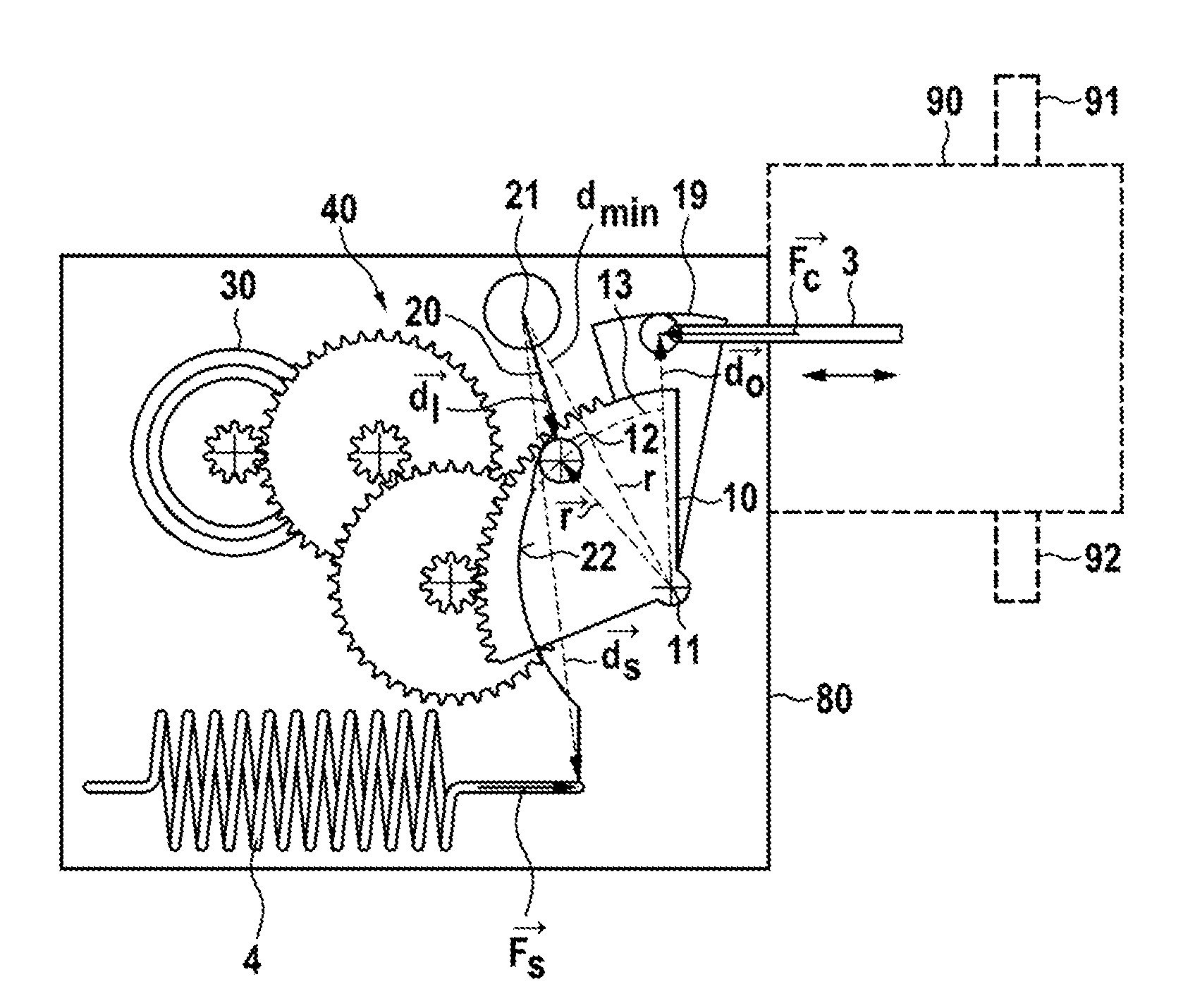
[0033] In FIG. 1 an exemplary embodiment of a clutch actuation mechanism is shown. The clutch operating mechanism has a support 80, being symbolized by a frame. The support 80 supports a motor 30 driving a disc 10 via a symbolized reduction gear 40. The motor 30 could as well drive the disc 10 via a shaft or directly, but the reduction gear 40 is a preferred alternative. The motor is preferably an electric motor.
[0034] Only for completeness, it is noted that the disc 10 is rotatably supported relative to the support, enabling a rotation of the disc 10 around its rotary axis 11. In the depicted example, the disc 10 is represented by a disc segment 10 with a disc extension 19. The disc extension 19 and the disc 10 can be made of a single piece, i.e. form a unitary piece. A clutch operator 3, here in the form of a push rod is connected to the disc 10 at a distance d.sub.o, thus the lever arm is {right arrow over (d.sub.S)}. Advancing or retracting the clutch operator 3 enables to open or close the clutch 90. The clutch operator 3 transmits a force {right arrow over (F.sub.C )} required to open the clutch.
[0035] As usual, the clutch 90 has an input shaft 91 and an output shaft 92 which can be connected enabling a torque transmission between said two shafts 91, 92. Spring loaded friction clutches 90 are known in the prior art and thus it is symbolized by a dashed box, only. To summarize: a rotation of the motor 30 is transmitted via the reduction gear into a rotation of the disc 10, and thus in principle enables to advance or retract the clutch operator 3, if the torque provided by the motor via the reduction gear is sufficient to compensate the force {right arrow over (F.sub.C)} or more precisely the torque {right arrow over (M.sub.C)}={right arrow over (F.sub.C)}.times.{right arrow over (d.sub.0)}.
[0036] To keep the motor torque low, an additional torque is provided by a spring 4 via a lever 20. The lever 20 is pivotable supported by the support 80. The lever's pivot axis 21 is at least essentially parallel (.+-.5.degree.) to the rotary axis 11 of the disc 10. The spring 4 presses a curved contacting surface 22 of the lever 20 against a pin 12 being connected to the disc 10 at distance r from the rotary axis 11. Thus the lever 20 provides an additional torque {right arrow over (M.sub.l)} to the disc, thereby supporting the motor 30. The additional torque {right arrow over (M.sub.l)} provided to the disc 10 depends on the force {right arrow over (F)}.sub.S provided by the spring to the lever 20 at the lever arm {right arrow over (d)}.sub.S, the angle of attack of the lever 20 to the pin 12 and the lever arm {right arrow over (d)}.sub.l of the lever 20 relative to the pin 12.
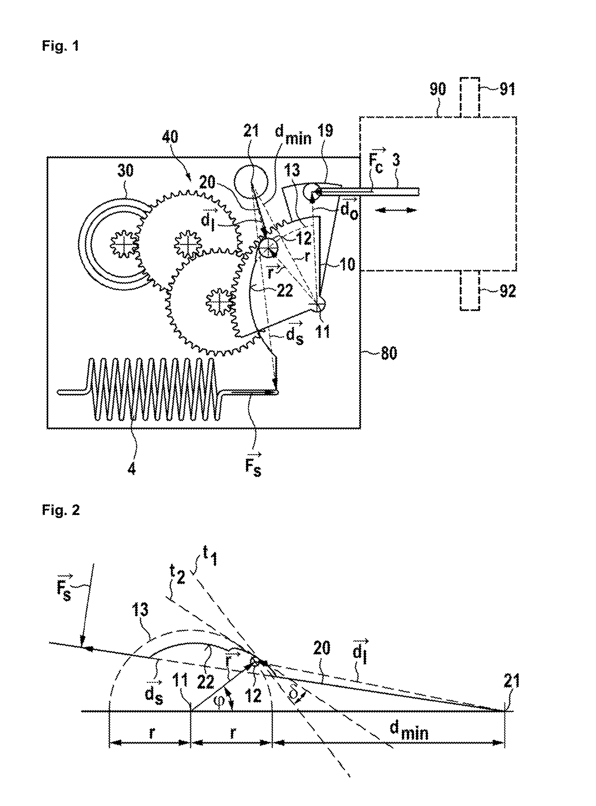
[0037] To simplify an understanding of the clutch actuation mechanism, FIG. 2 shows a simplified picture of a similar clutch actuation mechanism making use of the same principle. A lever 20 with a first lever arm {right arrow over (d)}.sub.S is forced by a spring force {right arrow over (F)}.sub.S against a pin 12, being rotatable relative to a rotary axis 11. The pin 12 may thus travel along a circular path 13. The vector {right arrow over (r)} indicates the lever arm of the pin 12. The vector {right arrow over (r)} thus rotates around the rotary axis 11 and forms an angle .phi. with a ray from the rotary axis 11 through the pivot axis 21 ({right arrow over (r)}(.phi.=0)). As can be seen, the pin 12 travels over the contacting surface 22 when the disc 10 and thus the vector {right arrow over (r)} rotates. Thus, the lever arm is a function of the angle .phi., the length r of the vector {right arrow over (r)} and the distance between the pin 12 at .phi.=0 and the pivot axis 21. Said distance is referred to as d.sub.min. When the pin 12 travels over the contacting surface 22, the angle between the normal of the contacting surface at the position where the pin 12 contacts the contacting surface varies as a function of .phi.. This angle can be reflected by the angle .delta. of the tangents t.sub.1 and t.sub.2, wherein t.sub.1 is the tangent of the contacting surface 22 at the position of the pin 12, and t.sub.2 the tangent of the circular path 13 at the pin's 12 corresponding position. It is thus possible, to compensate the torque M.sub.C provided via the clutch operator 3 to the disc 10 by adjusting the angle .delta. of the lever as function of .phi., d.sub.min, r and {right arrow over (F)}.sub.S, wherein {right arrow over (F)}.sub.S={right arrow over (F)}.sub.0+{right arrow over (k)}.DELTA.l. {right arrow over (F)}.sub.0 is the force of the spring 4 at an initial length l.sub.0, {right arrow over (k)} the spring constant and .DELTA.l a change in length of the spring 4 relative to l.sub.0. A compensation of the torque {right arrow over (M)}.sub.C can be obtained by setting .delta.:
.delta. = Arcsin ( - M C r 2 sin ( .PHI. ) + ( d min + r ( 1 - cos ( .PHI. ) ) ) 2 r ( F 0 + k .DELTA. l ) d S ) .+-. .DELTA. .delta. , ##EQU00005##
[0038] provided that {right arrow over (F)}.sub.S is essentially orthogonal to the lever arm {right arrow over (d)}.sub.S. If the orthogonality is not provided this can be accounted for by selecting .delta.:
.delta. = Arcsin ( - M C r 2 sin ( .PHI. ) + ( d min + r ( 1 - cos ( .PHI. ) ) ) 2 r ( F 0 + k .DELTA. l ) d S sin ( .gamma. ) ) .+-. .DELTA. .delta. , ##EQU00006##
[0039] wherein .gamma. is the angle between {right arrow over (F.sub.S)} and {right arrow over (d.sub.S)}.
[0040] The above formulas can be understood easily starting from the demand that the additional torque M.sub.l provided via the lever 20 to disc 10 compensates for the torque M.sub.C, i.e. M.sub.l=-M.sub.C. M.sub.l equals the torque M.sub.S provided by spring 4, i.e. M.sub.l=M.sub.S. This enables to calculate the force F.sub.l provided by the lever at the contacting point via the contacting surface 22 to the pin 12:
F l = F S d S sin ( .gamma. ) d l . ##EQU00007##
[0041] d.sub.l can be expressed as a function of .phi., as
d l = ( r 2 sin 2 ( .PHI. ) + ( d min + r ( 1 - cos ( .PHI. ) ) ) 2 ) 1 2 . ##EQU00008##
[0042] As the torque M.sub.l is given as M.sub.l=F.sub.lr sin(.delta.), -M.sub.C reads:
- M C = sin ( .delta. ) r F S d S sin ( .gamma. ) d l , ##EQU00009##
[0043] the equation can be solved as:
.delta. = Arcsin ( - M C d l r F S d S sin ( .gamma. ) ) ##EQU00010##
[0044] Expressing d.sub.1 as function of .phi. and F.sub.S as a function of .DELTA.l yields:
.delta. = Arcsin ( - M C r 2 sin ( .PHI. ) + ( d min + r ( 1 - cos ( .PHI. ) ) ) 2 r ( F 0 + k .DELTA. l ) d S sin ( .gamma. ) ) ##EQU00011##
[0045] The description of FIG. 2 can be read equally with respect to FIG. 3, but the angles .phi. .delta. have been selected differently. Further the curvature of the lever arm is different to account for a different torque {right arrow over (M)}.sub.C to be compensated.
[0046] FIG. 4 shows a clutch actuating mechanism. The mechanism is similar to the mechanism as shown in FIG. 1 and generally the description of FIG. 1 can be read on FIG. 4 as well. The difference is that the pin 12 comprises a core 14 being attached to the disc 10. The core rotatably supports a toothed ring 15, i.e. a gear wheel 15. In turn the lever 20 is a toothed rack and the gear wheel 15 is geared with the lever 20. This gearing ensures that the ring 15 rotates on the core 14 and friction and wear is reduced when the pin travels over the lever's contacting surface 22. The core 14 and the ring 15 provide plain bearing surfaces, but other bearings can be used as well. Beyond the description of FIG. 1 can be read on FIG. 4 as well.
[0047] The invention being thus described, it will be obvious that the same may be varied in many ways. Such variations are not to be regarded as a departure from the spirit and scope of the invention, and all such modifications as would be obvious to one skilled in the art are to be included within the scope of the following claims.
* * * * *
D00000
D00001
D00002


XML
uspto.report is an independent third-party trademark research tool that is not affiliated, endorsed, or sponsored by the United States Patent and Trademark Office (USPTO) or any other governmental organization. The information provided by uspto.report is based on publicly available data at the time of writing and is intended for informational purposes only.
While we strive to provide accurate and up-to-date information, we do not guarantee the accuracy, completeness, reliability, or suitability of the information displayed on this site. The use of this site is at your own risk. Any reliance you place on such information is therefore strictly at your own risk.
All official trademark data, including owner information, should be verified by visiting the official USPTO website at www.uspto.gov. This site is not intended to replace professional legal advice and should not be used as a substitute for consulting with a legal professional who is knowledgeable about trademark law.