System And Method For Controlling Window Blinds
Barnett; Eric
U.S. patent application number 16/157551 was filed with the patent office on 2019-02-07 for system and method for controlling window blinds. The applicant listed for this patent is Eric Barnett. Invention is credited to Eric Barnett.
| Application Number | 20190040677 16/157551 |
| Document ID | / |
| Family ID | 61009436 |
| Filed Date | 2019-02-07 |


View All Diagrams
| United States Patent Application | 20190040677 |
| Kind Code | A1 |
| Barnett; Eric | February 7, 2019 |
SYSTEM AND METHOD FOR CONTROLLING WINDOW BLINDS
Abstract
A window blind control system includes a control device, having a housing; a motor connected to one or more gears positioned within the housing; a hollow drive shaft coupled to the one or more gears, the hollow drive shaft to receive a window blind tilt rod; a control system having a communication board associated with a home automation wireless mesh protocol to communicate with one or more networked devices; a home automation system including the one or more networked devices; an interface accessible from a computing device and to communicate with the home automation system and the control device, the interface is to receive commands from a user.
| Inventors: | Barnett; Eric; (Fort Worth, TX) | ||||||||||
| Applicant: |
|
||||||||||
|---|---|---|---|---|---|---|---|---|---|---|---|
| Family ID: | 61009436 | ||||||||||
| Appl. No.: | 16/157551 | ||||||||||
| Filed: | October 11, 2018 |
Related U.S. Patent Documents
| Application Number | Filing Date | Patent Number | ||
|---|---|---|---|---|
| 15067306 | Mar 11, 2016 | |||
| 16157551 | ||||
| 62134043 | Mar 17, 2015 | |||
| Current U.S. Class: | 1/1 |
| Current CPC Class: | E06B 9/368 20130101; E06B 9/322 20130101; G08C 17/02 20130101; E06B 9/364 20130101; E06B 2009/6818 20130101; E06B 9/307 20130101; F16H 1/06 20130101; G08C 2201/31 20130101; E06B 2009/3222 20130101 |
| International Class: | E06B 9/322 20060101 E06B009/322; E06B 9/36 20060101 E06B009/36; F16H 1/06 20060101 F16H001/06; E06B 9/307 20060101 E06B009/307; G08C 17/02 20060101 G08C017/02 |
Claims
1. A window blind control system, comprising: a control device, having: a housing; a motor connected to one or more gears positioned within the housing; a hollow drive shaft coupled to the one or more gears, the hollow drive shaft configured to receive a window blind tilt rod; a control system having a communication board associated with a home automation wireless mesh protocol configured to communicate with one or more networked devices and a home automation controller; a home automation system including the one or more mesh networked devices, the home automation system being configured to communicate with the control device; and an interface accessible from a computing device and configured to communicate with the home automation system and the control device, wherein the interface is configured to received commands from a user; wherein the control device is configured to tilt the window blinds to open and closed positions.
2. The system of claim 1, wherein the hollow drive shaft includes a hexagonal opening.
3. The system of claim 1, wherein the hollow drive shaft includes a square opening.
4. The system of claim 1, wherein the communication board is a Z-Wave protocol.
5. The system of claim 1, wherein the communication board is a Zigbee protocol.
6. The system of claim 1, wherein the motor comprises: a dual shaft motor with an attached magnetic encoder.
7. The system of claim 7, wherein the magnetic encoder comprises: a Hall effect sensor; and a 6 pole magnetic disc.
8. The system of claim 1, wherein the control system comprises: an auto calibration control configured to find a blind end point max tilt closed down and a max tilt closed up position based on the calculated force required to tilt the blinds closed in either direction.
9. The system of claim 1, further comprising: a height adapter configured to elevate the housing.
10. The system of claim 1, further comprising: a pass through adapter configured to be mounted on a blinds headrail, the pass through adapter having: a single button accessible from an exterior blinds headrail, the single button being configured to command the control system based on a plurality of push patterns, wherein each of the plurality of push patterns sends a different command.
11. The system of claim 10, the passthrough adapter further comprising: a manual rotary switch extending from the housing and configured to allow for manual adjustment.
12. The system of claim 1, wherein the housing further comprises: a power port configured to receive a power source.
13. The system of claim 12, wherein the power source comprises one or more of: a USB adapter configured to connect to an AC outlet to supply direct power; a USB adapter configured to connect to an AC outlet and recharge a rechargeable battery; and a solar panel configured to recharge the rechargeable battery.
14. The system of claim 1, wherein the control system comprises: an adjustable speed control configured to allow the user to adjust a speed of blind operation; an adjustable torque control configured to allow the user to adjust a torque force of blind operation;
15. The system of claim 1, wherein the communication board is removable and replaceable.
16. The system of claim 1, wherein the control system is configured to receive a command from one of the one or more networked devices to tilt open or close the blinds based on a predetermined value reached by the one of the one or more networked devices.
17. The system of claim 1, further comprising: a set screw configured to be inserted through a thickness of the hollow drive shaft to secure the tilt rod in place within the hollow drive shaft.
18. The system of claim 1, further comprising: a fixing unit having a channel surrounding the motor, the fixing unit containing a noise damping material and configured to secure within the housing; wherein the mount isolates the motor from the housing to reduce noise.
19. The system of claim 1, wherein the control system is a printed circuit board.
Description
BACKGROUND
1. Field of the Invention
[0001] The present invention relates generally to window blind systems, and more specifically, to a system and method for remotely controlling window blinds.
2. Description of Related Art
[0002] Window blinds are used in homes to control inlet of sunlight to homes. A conventional window blind system includes a headrail that is fixed at top of the window. Further, the window blind system includes a blind assembly suspended from the head rail. The angle of the blinds can be controlled by application of an external force in order to tilt the window blinds that changes the amount of sunlight entering the home through the window.
[0003] Various types of mechanisms are available to lift or change the tilt angle of the window blinds. Some window blind systems may have a visible lift cord and tilt cord to change the tilt angles of the window blinds. One disadvantage of these systems is that since the lift cord and tilt cords are visible, it is accessible to children and can be pulled or stretched by them, while playing that may cause an accident.
[0004] Further disadvantages include insecurity, for example thieves can monitor window blind movement to gage if someone is home or away on vacation. With an automated solution you can schedule your blinds to open and close when you are away.
[0005] Yet another disadvantage includes energy inefficiency, for example heat comes in during the summer and/or blocked during the winter. With an automated solution you can choose to let the light in or control how your blinds provide insulation.
[0006] There are other window blinds systems where the tilt cord or lift cords are hidden and are not easily accessible or are concealed. In some window blind systems having concealed cords, there is provided a spring means to keep the blinds in balance and to hold the blinds and bottom rail in position after an adjustment of the blinds. There are other window blind systems known in the market, with concealed cords, which uses a tension force of a positioning cord in order support the bottom rail in position after an adjustment of the window blinds. However, the use of spring is always prone to elastic fatigue. After some time of usage, when the elastic fatigue kicks in, the spring mechanism or the positioning cord system cannot support the bottom rail accurately in position. Also, majority of these designs are used for controlling the elevation of the blinds only. For controlling the tilt angle of the blinds, additional tilting rod and mechanism must be added to the already complex window blind system. Since, the lifting and tilting angle of the blinds is separately controlled.
[0007] Unfortunately, when it comes to controlling horizontal blinds no product is on the market that directly operates with existing home automation systems using a wireless mesh network protocol to conveniently and easy control the tilting of blinds. Accordingly, the present invention provides for a system and method with the ability to integrate into home automation wireless mesh protocols for the control of window blinds conveniently.
DESCRIPTION OF THE DRAWINGS
[0008] The novel features believed characteristic of the embodiments of the present application are set forth in the appended claims. However, the embodiments themselves, as well as a preferred mode of use, and further objectives and advantages thereof, will best be understood by reference to the following detailed description when read in conjunction with the accompanying drawings, wherein:
[0009] FIG. 1 is a simplified schematic of a system for controlling window blinds in accordance with a preferred embodiment of the present application;
[0010] FIG. 2 is an oblique view of the control device of FIG. 1;
[0011] FIG. 3 is a line diagram of the control device of FIG. 1 installed with blinds;
[0012] FIG. 4 is a line diagram depicting a pass-through adapter of FIG. 3;
[0013] FIG. 5 is an oblique view of a control device of FIG. 1 with an elevation device and a lid in accordance with an embodiment of the present application;
[0014] FIG. 6 is an isometric view of a hollow shaft of FIG. 2;
[0015] FIGS. 7 is an end view of a first embodiment of the hollow shaft of FIG. 6;
[0016] FIG. 8 is an end view of a second embodiment of the hollow shaft of FIG. 6;
[0017] FIG. 9 is an end view of a third embodiment of the hollow shaft of FIG. 6;
[0018] FIG. 10 is simplified top line drawings of a control device of FIG. 1;
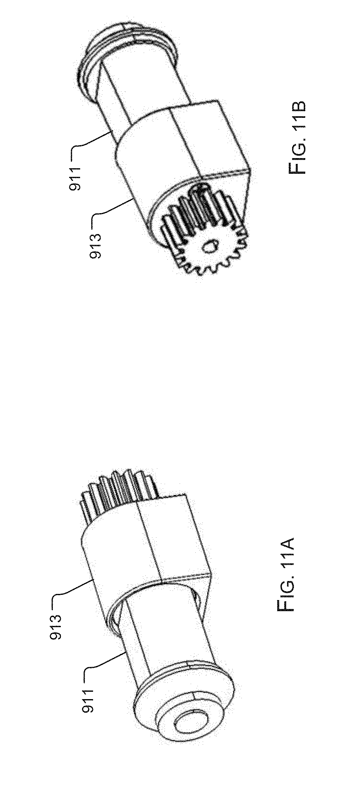
[0019] FIGS. 11A and 11B are isometric front and back views of a motor fixing unit of FIG. 10;
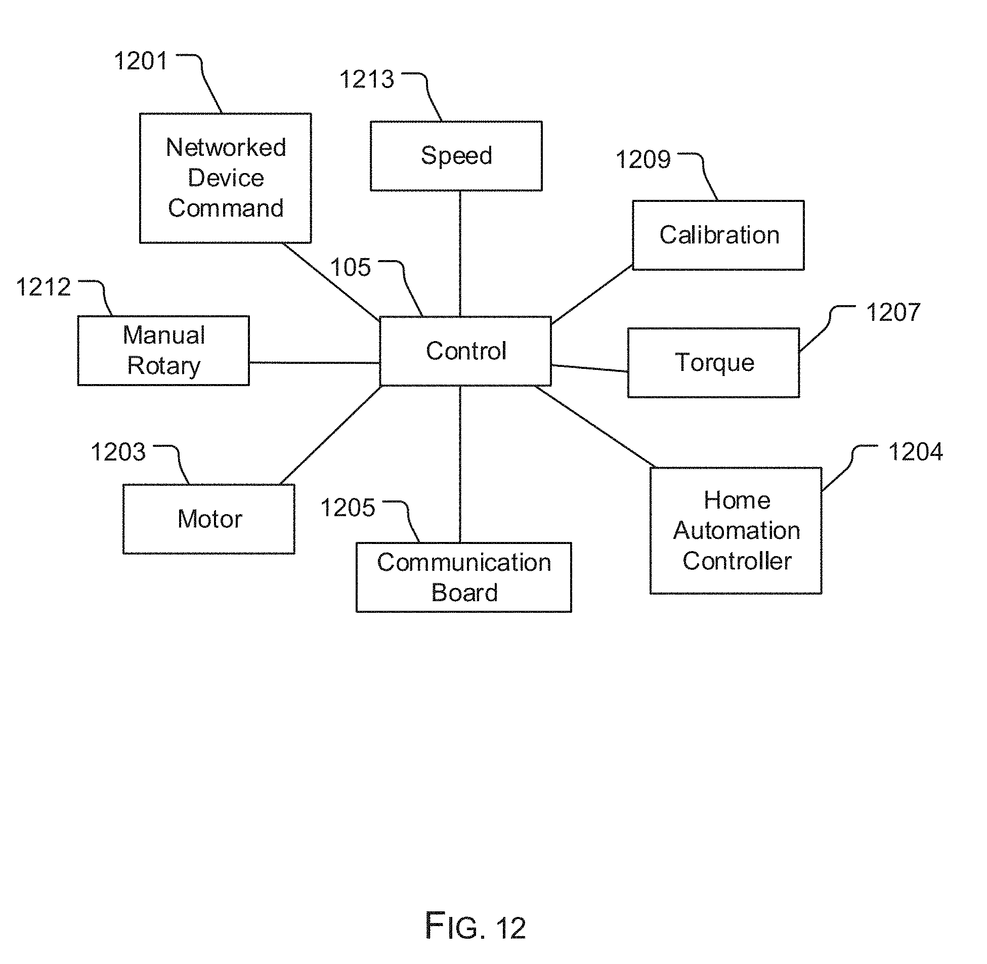
[0020] FIG. 12 is a schematic of the control system of FIG. 1;
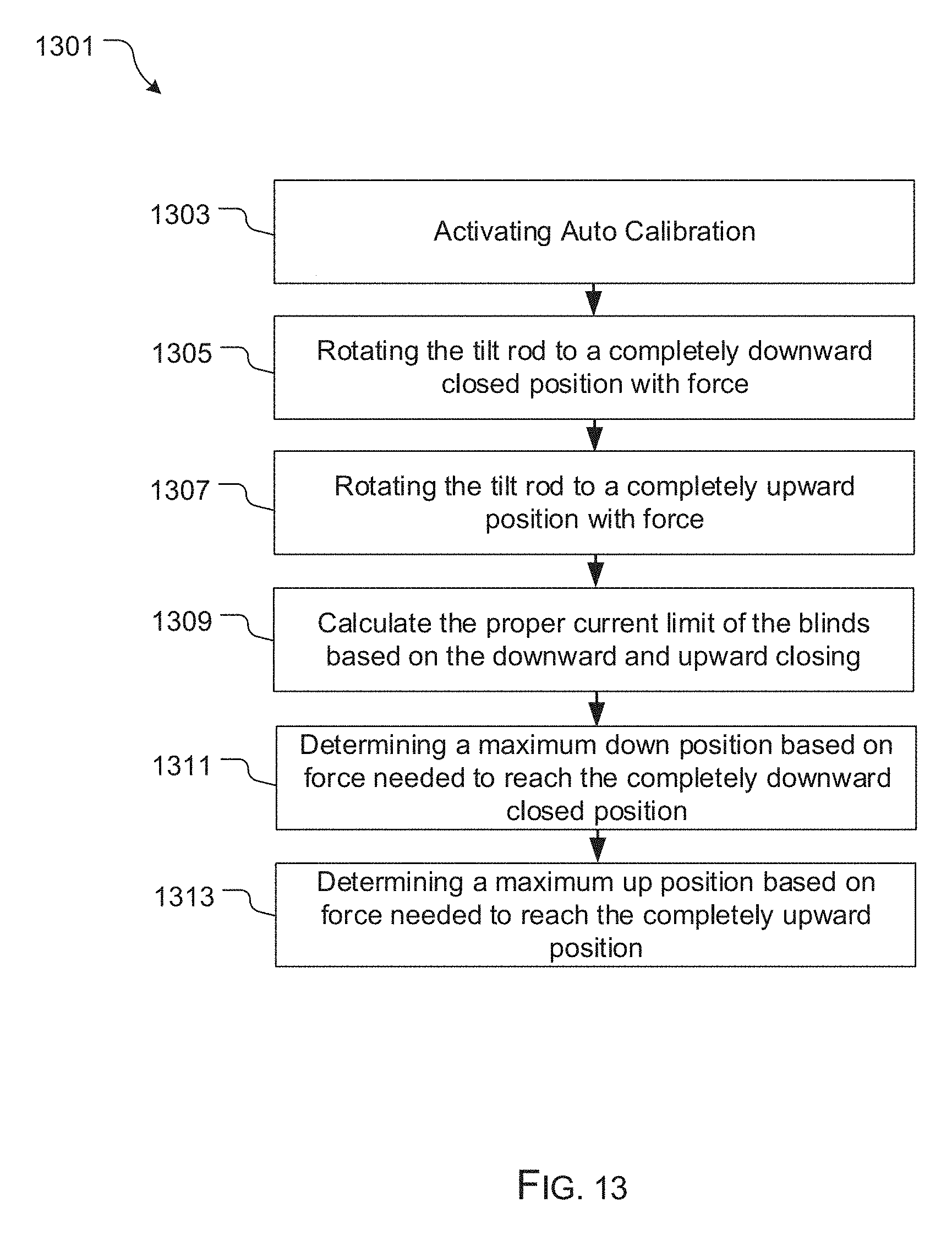
[0021] FIG. 13 is a flowchart of the method of calibration associated with the control system of FIG. 11; and
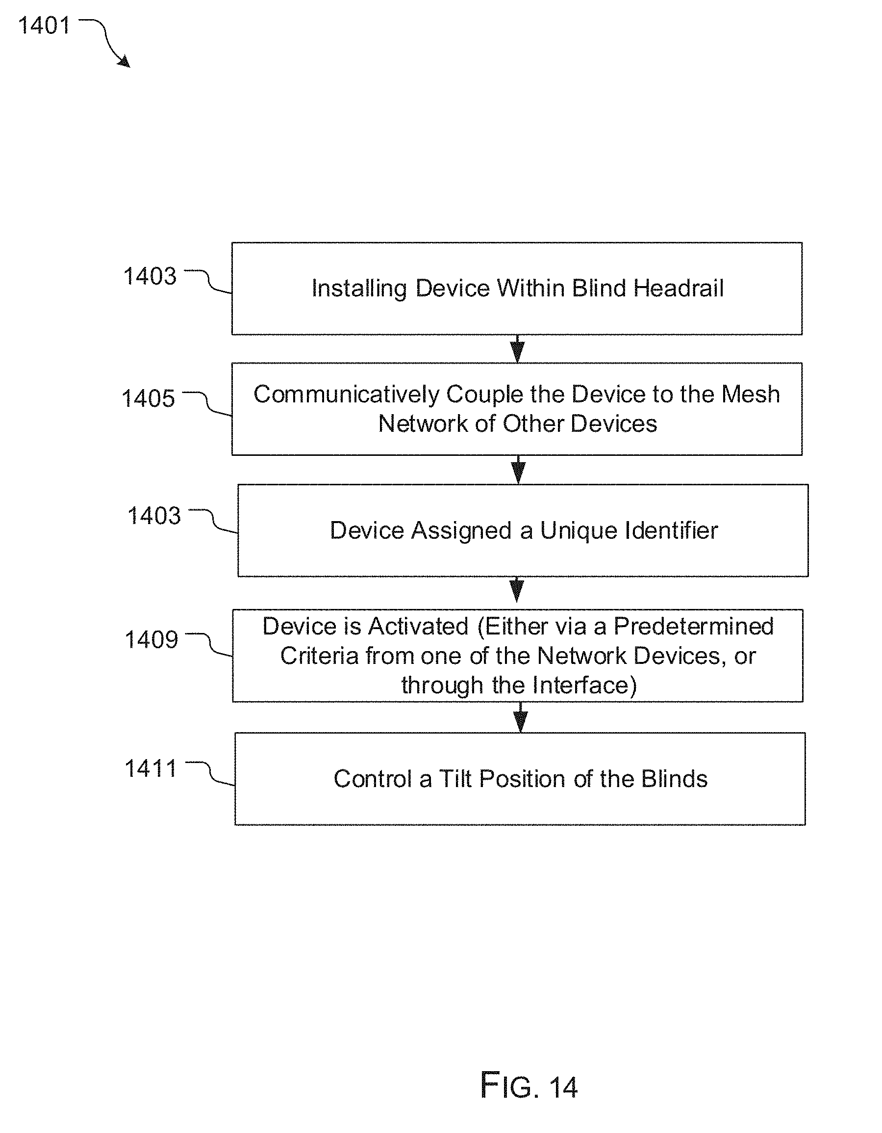
[0022] FIG. 14 is a flowchart of the method of use of the system of FIG. 1.
[0023] While the system and method of use of the present application is susceptible to various modifications and alternative forms, specific embodiments thereof have been shown by way of example in the drawings and are herein described in detail. It should be understood, however, that the description herein of specific embodiments is not intended to limit the invention to the particular embodiment disclosed, but on the contrary, the intention is to cover all modifications, equivalents, and alternatives falling within the spirit and scope of the present application as defined by the appended claims.
DETAILED DESCRIPTION OF THE PREFERRED EMBODIMENT
[0024] Illustrative embodiments of the system and method of use of the present application are provided below. It will of course be appreciated that in the development of any actual embodiment, numerous implementation-specific decisions will be made to achieve the developer's specific goals, such as compliance with system-related and business-related constraints, which will vary from one implementation to another. Moreover, it will be appreciated that such a development effort might be complex and time-consuming, but would nevertheless be a routine undertaking for those of ordinary skill in the art having the benefit of this disclosure.
[0025] The system and method of use in accordance with the present application overcomes one or more of the above-discussed problems commonly associated with conventional blind control systems. Specifically, the present invention provides for a blind tilt control device as a part of a home automation system that can be controlled via an interface, or automatically based on commands received from other networked devices within the home automation system. These and other unique features of the system and method of use are discussed below and illustrated in the accompanying drawings.
[0026] The system and method of use will be understood, both as to its structure and operation, from the accompanying drawings, taken in conjunction with the accompanying description. Several embodiments of the system are presented herein. It should be understood that various components, parts, and features of the different embodiments may be combined together and/or interchanged with one another, all of which are within the scope of the present application, even though not all variations and particular embodiments are shown in the drawings. It should also be understood that the mixing and matching of features, elements, and/or functions between various embodiments is expressly contemplated herein so that one of ordinary skill in the art would appreciate from this disclosure that the features, elements, and/or functions of one embodiment may be incorporated into another embodiment as appropriate, unless described otherwise.
[0027] The preferred embodiment herein described is not intended to be exhaustive or to limit the invention to the precise form disclosed. It is chosen and described to explain the principles of the invention and its application and practical use to enable others skilled in the art to follow its teachings.
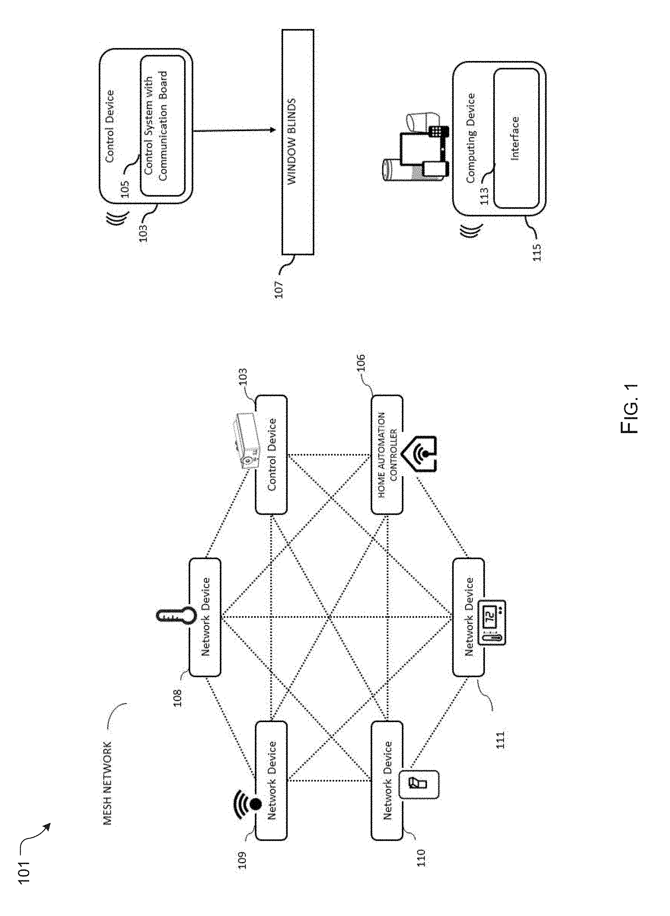
[0028] Referring now to the drawings wherein like reference characters identify corresponding or similar elements throughout the several views, FIG. 1 depicts a simplified diagram of a home automation mesh network system 101 in accordance with a preferred embodiment of the present application. It will be appreciated that system 103 overcomes one of more of the above-listed problems commonly associated with conventional window blind control systems.
[0029] In the contemplated embodiment, system 101 includes a window blind control device 103 configured to engage with a tilt rod of conventional window blinds, and thereby tilt window blind slats to open and closed positions of the window blinds 107 via a control system 105. The control system can vary in components, some embodiments including a PCB, the control system having a communication board configured with a home wireless network mesh protocol configured to provide a means to incorporate the device 103 into a home network. The system further includes the home automation mesh network, which includes a plurality of networked devices 108, 109, 110, 111 and/or a home automation controller, all being able to communicate with each other, as well as a computing device 115 with an interface 113.
[0030] It should be appreciated that the various devices 103, 108, 109, 110, 111 can receive commands based on the user's desires through interface 113 or through other means, such as a home automation controller 106. For example, one device may be a home thermostat that the user can control remotely. In addition, it should be appreciated that control system 105 is configured to be commanded based on one or more sensors, such as a temperature or light sensor, incorporated into the networked devices or device 103, wherein the control device will alter the blinds tilt position based on a predetermined criteria, such as a temperature, or a light level. Examples of home automation controllers 106 include devices, such as, but not limited to, Wink Hub, Smart Things Hub, and so forth. Further, each of the networked devices has an associated unique identifier. Examples of the wireless mesh network protocol may include, but are not limited to, Bluetooth MESH, Radio Frequency (RF) control, Z-Wave, ZigBee, FabFi, SolarMesh, WING, Wireless Backhaul (WiBACK) and so forth. It is contemplated that an Amazon Alexa.RTM. can be configured as the computing device 115 with interface 113 to provide a means of commands.
[0031] One of the main advantages of such a network is that the devices to be controlled need not be placed near each other, the home automation controller 106 or the computing device 115. The device to be controlled can be accessed by relaying control signals from other network devices connected to the same home automation controller.
[0032] Further, the device 103 can be configured to operate in one or more modes such as, a primary mode (automated) and a secondary mode (manual). In the automated mode of operation of the device 103 can be controlled by the computing device 115 communicating with the home automation controller, wherein the user merely inputs a command through the interface.
[0033] A second automated mode involves association between the control device 103 and one or more of the other networked devices. An example includes the control of device 103 based on change in temperature in the environment surrounding the device 103 or the window blinds 107. In yet another mode of operation, the device 103 may control the opening and closing of the window blinds 107 based on a position of the mesh networked devices 109 or computing devices 115 such as a mobile phone of the user, a smart watch, a laptop, and so forth. For example, the network sensors interfacing the device 103 may sense when the networked device approaches the device 103 or is within a predefined area nearby, and the opening and closing of the window blinds may be controlled accordingly. The control system may also control the window blinds at a site using a proximity detection of a mobile device or the networked device, which may be based upon the detection of a number of zones. Each of the zones may be associated, with a predefined temperature threshold of a thermostat or the control system included in that device or other energy consuming device.
[0034] Further, the temperature threshold corresponding to a zone may be different from the temperature thresholds corresponding with each of the other zones. A database of the interface may store multiple values such as, a position threshold, a plurality of temperature thresholds, a plurality of times, a plurality of voice commands. The device may be configured to receive the voice commands from the computing device interface and process them based on comparison of prestored voice commands for controlling the opening and closing of the window blinds.
[0035] In another mode of example, the device may control the window blinds based on a sunrise a sunset schedule. This mode of operation can be coupled by providing interfacing of the device with a plurality of network connected photo-sensors as the one or more networked devices. The photo-sensors sense the absence or presence of sunlight using the photoelectric receiver.
[0036] A third automated mode includes use of the interface and the computing device to send a command to the control device. This could include the user setting a time through the computing device which commands the control device to open or close the blinds.
[0037] The secondary operational mode allows the device 103 to be operated in manual mode using a manual rotary switch that will be discussed later in detail. In this embodiment of the invention, there may be an input device connected to the device 103 like a remote control or a manual rotary switch. Through this remote control or the manual rotary switch, a user can control the device 103 for tilting of the window blinds.
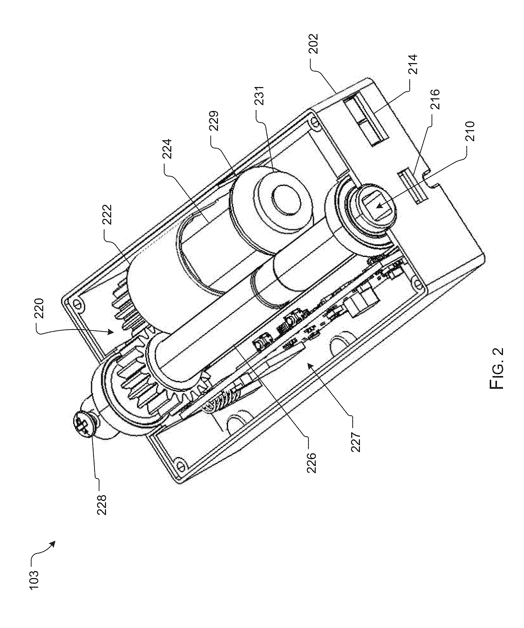
[0038] Now, referring to FIG. 2 control device 103 for controlling tilt angle of window blinds is shown. Device 103 is configured to be fitted into any existing horizontal window blind system. Also, the device 103 is so configured that it can work with an existing home automation controller installed within a home. The device 103 includes a housing 202 that encloses various parts of the device 103. The housing 202 may be made up of anyone of a plastic, a metal, or a fiber.
[0039] The housing 202 may further include a top lid (shown in FIG. 4) that may be opened to access internal parts of the device 103. The device 103, further includes a tilt rod receiving opening 210 into a shaft 226 that extends through a length of the housing. As discussed later herein, the shaft 226 includes variously sized, and shaped openings 210 which can thereby allow for use with one or more sizes, shapes, and the like of window blind tilt rod adapters. Further, the shaft can include a set screw 228 to secure the shaft to the tilt rod passing through.
[0040] The device can include a port 214 for receiving a USB charger or the like. In the preferred embodiment, the device 103 can be powered in one of three ways, including direct 5V powered supplied from USB adapter; a rechargeable battery and USB charger; and a rechargeable battery and a solar panel. The device 103 can further include an auxiliary power ports 216 for solar panel connection.
[0041] The device 103 includes a motor 224 with a motor fixing unit 222. In an embodiment of the invention, the motor 224 is a Direct Current (DC) motor with a hall effect sensor 229 and a 6 pole magnet 231. Examples of the DC motor may include, but are not limited to, a DC brush motor, a stepper motor, etc. The motor 224 is placed inside the device 103 using the motor fixing unit 222.
[0042] Further, the motor engages with a gear system 220 to rotate the shaft. The hollow drive shaft 226 is placed in a manner wherein, the hollow drive shaft 226 passes through the housing and engages with tilt rod. The PCB/Control system 227 shall include a transeiving unit (not shown in figure) that helps the device 103 to communicate with other devices like existing wireless home controller through wireless communication. The communication can be through a home automation wireless mesh protocol wherein the protocol is chosen from a group comprising a ZigBee protocol, Bluetooth MESH, Thread., FabFi, Solar mesh, WING, Wireless Backhaul, and a Z-wave protocol.
[0043] The disclosed invention may be implemented using any other suitable existing mesh network standard Examples of the wireless mesh network protocol may include, but are not limited to, Bluetooth MESH, Radio Frequency (RF) control, Z-Wave, ZigBee, Thread, FabFi, Solar Mesh, WING, Wireless Backhaul (WiBACK) and so forth. The motorized device for control of horizontal window blinds tilt position is not limited to the specific methods described by the Z-Wave standard. The invention can be adapted or scaled to use other home automation mesh network profile standards such as, but not limited to, those defined by Z-wave. In addition, it is contemplated that the communication board can be removable and replaceable. This will allow users the ability to continue to use the device and just swap out the communication board.
[0044] The control system of the device is configured to store data and settings, the data including at least a unique identifier associated with the device.
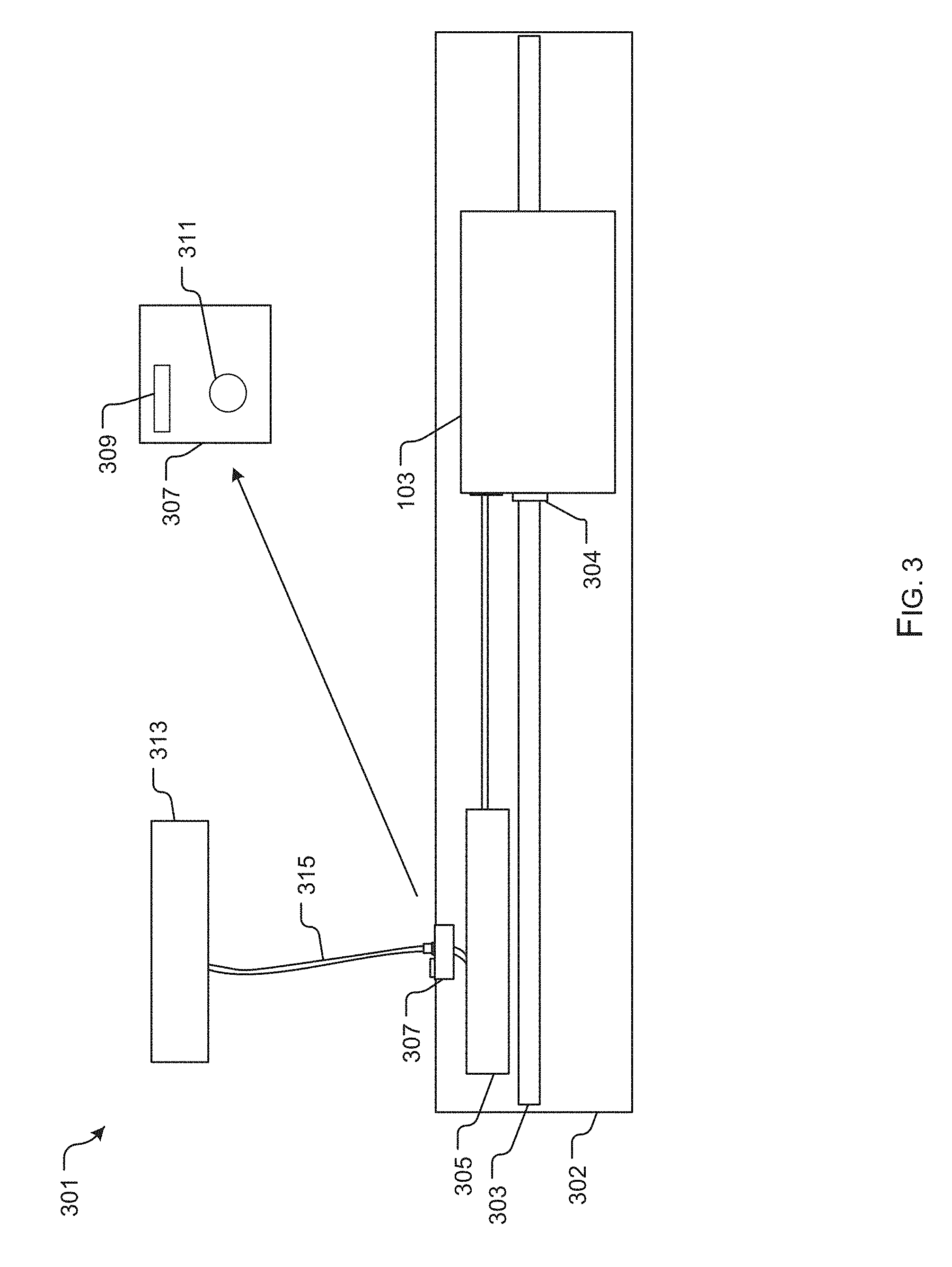
[0045] In FIG. 3, a simplified diagram depicts a window control system 301, having the control device 103 positioned within a headrail 302 and engaged with a tilt rod 303 via an hollow drive shaft 304. The device 103 is configured to receive power from a power source 305. It should be appreciated that a pass through adapter 307 can be positioned to communicate with an exterior of the headrail 302. The adapter 307 can have a button/switch 311 and a charging port 309, as shown in the detailed view. The button/switch 311 in one embodiment is a single button, that is configured to communicate with the control system and can provide commands based on the number of times pressed. This provides for a simple means for a user to send commands, such as a calibration command, to device 103. Further, the button/switch 311 can be rotary switch, which can provide for manual operation of the device 103.
[0046] Device 103 can function with a plurality of power options. One option includes a direct power source, wherein a cord runs from the device and plugs directly into an AC outlet (not shown). A second option includes a rechargeable battery 305 which can receive charge from a power source 313 (in this embodiment the power source is a solar panel). A third option includes the rechargeable battery 305 and a USB adapter and cable 315 configured to charge the rechargeable battery every 6 months via the power source 313 in this embodiment the power source is an AC outlet).
[0047] In FIG. 4, an oblique view of a pass through adapter 307 is shown, having a manual rotary switch 401 and one or more ports 403.
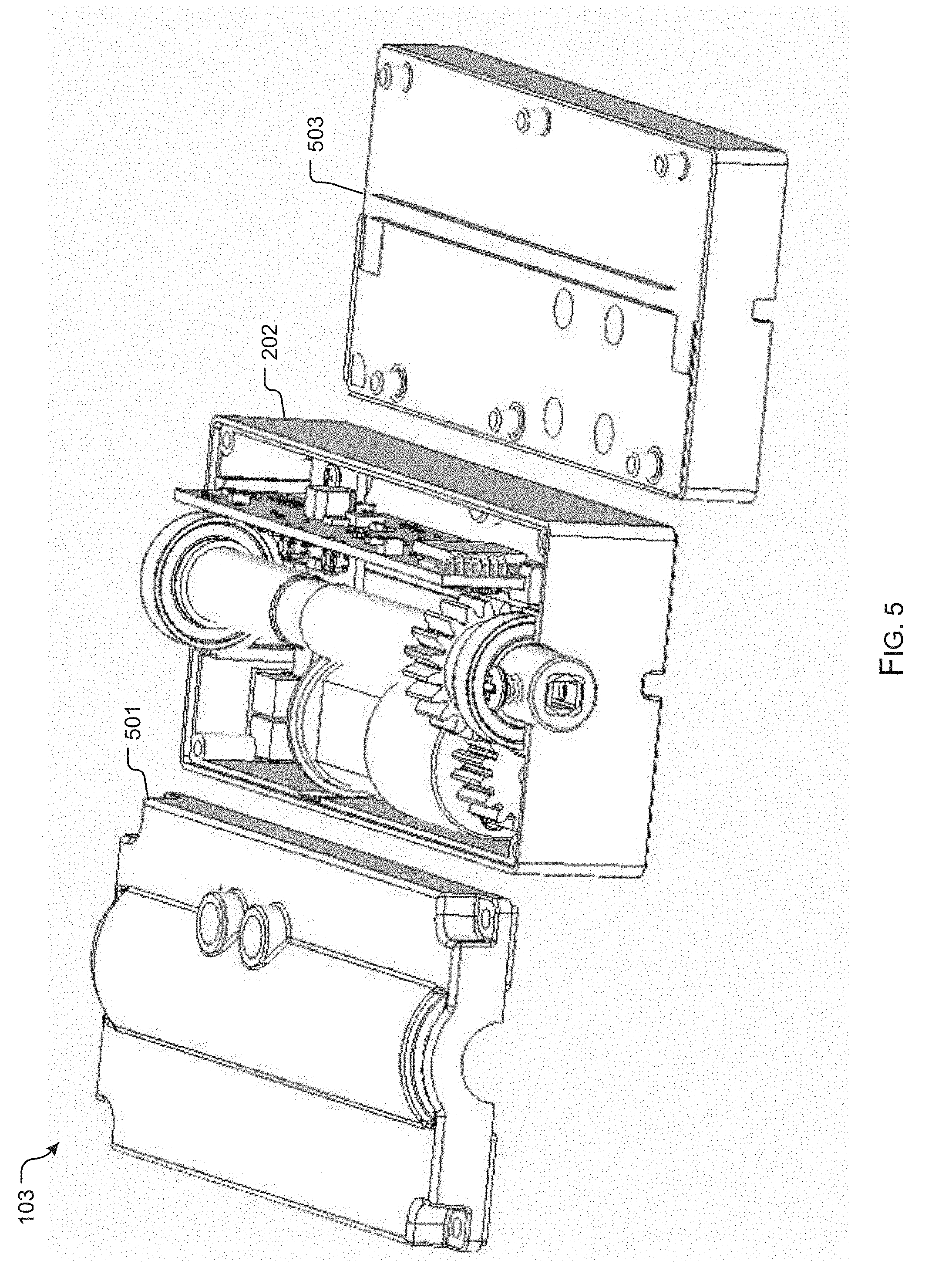
[0048] In FIG. 5, a detailed view of control device 103 is shown, wherein the housing 202 includes lid 501 and can further be adapted for elevation via an elevation device 503 that provides a means to elevate the device and thereby function with variously sized blind systems.
[0049] FIG. 6 further depicts a clear view of hollow drive shaft 226, with an opening 210 and the configuration of set screw 228. In FIGS. 7-9, end views of alternative embodiments of hollow drive shaft 226 are shown, wherein embodiment 701 includes a square opening 703 configured to receive a square tilt rod of a first size. Embodiment 801 includes a hexagonal opening 803 configured to receive a hexagonal shaped tilt rod. Further, embodiment 901 includes a square opening 903 of a second size.
[0050] In FIG. 10, a simplified diagram further depicts the components of device 103. Device 103 includes a housing 1001 with an interior area 1003 housing a hollow drive shaft configured to receive the tilt rod adapter. The hollow drive shaft 1005 is in communication with a motor 1011 via one or more gears 1007, 1009. In some embodiments, the motor is a dual shaft motor with an attached magnetic encoder. In the preferred embodiment, the magnetic encoder includes a Hall effect sensor; and a 6 pole magnetic disc. In some embodiments, the motor is mounted with a mount motor fixing unit 1013, the fixing unit having a channel and containing a vibration absorbing material to reduce noise. In FIGS. 11A and 11B, a fixing unit 1013 is shown around motor 1011. The mount isolates the motor from the housing to reduce noise.
[0051] The control system 1015 which can be a printed circuit board, or the like, is configured to command the motor and thereby activate opening and closing of the blinds. One or more buttons 1023a, 1023b can be positioned on the PCB and can provide a means to command the device, such as an auto calibration, or the like. Further, one or more power port 1020 is preferably located on the housing to provide a means to connect to the power source, as discussed herein.
[0052] In some embodiments, a set screw 1019 is configured to be inserted through a hole 1017 within the shaft 1005, thereby securing the shaft to the tilt rod. The set screw 1019 provides for a stronger coupling, wherein there is less chance of the plastic being stripped or slippage.
[0053] In FIG. 12, components of control system 105 are shown. The control system 105 can be configured to alter the speed 1213 of opening and closing, and the torque 1207 applied to the tilt rod via the motor 1203. Further, as discussed previously, the control system 105 includes a communication board 1205 to provide for communication with networked devices 1201, computing devices, a home automation controller 1204, and the like. The control system 105 includes a calibration control 1209 configured to calibrate the device. Further, manual rotary 1212 provides for a means of control.
[0054] In FIG. 13, a flowchart 1301 depicts the method of calibration. The autocalibration is activated, wherein the control system operates to rotate the tilt rod to a completely closed, downward position, as shown with boxes 1303, 1305. The control system then proceeds to rotate the tilt rod to a completely upward position, as shown with box 1307. The calibration tool then calculates the proper current limit based on the force needed to force the blinds closed in both directions, as shown with box 1309. This data provides necessary details for the control system to calculate a maximum down and up position, thereby calibrating the device, as shown with boxes 1311, 1313.
[0055] In FIG. 14, a flowchart 1401 depicts a method of use of the system discussed herein. During use, the control device is installed within the blind headrail and is communicatively coupled to the mesh network and network device, as shown with boxes 1403, 1405. The device is assigned a unique identifier, as shown with box 1407. The device is then activated, as shown with box 1409. It should further be appreciated that the device may be activated based on a command received through the interface and the control system, or in alternative embodiment, as networked device determines a criteria (such as temperature or light), a command is sent to the device to perform a function. The device the alters the tilt position of the blinds, as shown with box 1411.
[0056] The particular embodiments disclosed above are illustrative only, as the embodiments may be modified and practiced in different but equivalent manners apparent to those skilled in the art having the benefit of the teachings herein. It is therefore evident that the particular embodiments disclosed above may be altered or modified, and all such variations are considered within the scope and spirit of the application. Accordingly, the protection sought herein is as set forth in the description. Although the present embodiments are shown above, they are not limited to just these embodiments, but are amenable to various changes and modifications without departing from the spirit thereof.
* * * * *
D00000
D00001
D00002
D00003
D00004
D00005
D00006
D00007
D00008
D00009
D00010
D00011
D00012
XML
uspto.report is an independent third-party trademark research tool that is not affiliated, endorsed, or sponsored by the United States Patent and Trademark Office (USPTO) or any other governmental organization. The information provided by uspto.report is based on publicly available data at the time of writing and is intended for informational purposes only.
While we strive to provide accurate and up-to-date information, we do not guarantee the accuracy, completeness, reliability, or suitability of the information displayed on this site. The use of this site is at your own risk. Any reliance you place on such information is therefore strictly at your own risk.
All official trademark data, including owner information, should be verified by visiting the official USPTO website at www.uspto.gov. This site is not intended to replace professional legal advice and should not be used as a substitute for consulting with a legal professional who is knowledgeable about trademark law.