Hand Washing Device
KOMAKI; Hideyuki ; et al.
U.S. patent application number 16/072990 was filed with the patent office on 2019-02-07 for hand washing device. The applicant listed for this patent is LIXIL CORPORATION. Invention is credited to Hideyuki KOMAKI, Yuichiro KOMATSU, Takahiro KONDOU, Kousuke YASUMA.
| Application Number | 20190040612 16/072990 |
| Document ID | / |
| Family ID | 59398385 |
| Filed Date | 2019-02-07 |


| United States Patent Application | 20190040612 |
| Kind Code | A1 |
| KOMAKI; Hideyuki ; et al. | February 7, 2019 |
HAND WASHING DEVICE
Abstract
Provided is a hand washing device with which malfunctions of a washing liquid dispenser can be prevented during hand washing without the need for a complex device structure. A hand washing device 1 comprises: a water discharger 10 that discharges water or hot water when an object is detected; and a washing liquid dispenser 20 that dispenses a washing liquid. The water discharger 10 includes: a water discharge port 12; a water discharge sensor 11 that detects an object within a detection range; and a water discharge control unit 16 that controls the discharge/cutoff of water or hot water from the water discharge port 12 on the basis of a detection signal of the water discharge sensor 11. The washing liquid dispenser 20 includes: a dispensing port 22; a washing liquid dispensing sensor 21 that detects an object within a detection range; and a washing liquid dispensing control unit 28 that controls the dispensing/cutoff of the washing liquid from the dispensing port on the basis of a detection signal of the washing liquid dispensing sensor. A sensor direction Y2, which is an emission direction of emission light that is emitted from the washing liquid dispensing sensor 21, is inclined further downward than a discharge direction X1 of water or hot water that is discharged from the water discharge port 12.
| Inventors: | KOMAKI; Hideyuki; (Tokyo, JP) ; KONDOU; Takahiro; (Tokyo, JP) ; KOMATSU; Yuichiro; (Tokyo, JP) ; YASUMA; Kousuke; (Tokyo, JP) | ||||||||||
| Applicant: |
|
||||||||||
|---|---|---|---|---|---|---|---|---|---|---|---|
| Family ID: | 59398385 | ||||||||||
| Appl. No.: | 16/072990 | ||||||||||
| Filed: | July 26, 2017 | ||||||||||
| PCT Filed: | July 26, 2017 | ||||||||||
| PCT NO: | PCT/JP2017/002662 | ||||||||||
| 371 Date: | July 26, 2018 |
| Current U.S. Class: | 1/1 |
| Current CPC Class: | E03C 1/057 20130101; E03C 1/0404 20130101; A47K 10/48 20130101; A47K 5/1217 20130101; E03C 1/042 20130101; E03C 1/046 20130101; A47K 2210/00 20130101 |
| International Class: | E03C 1/05 20060101 E03C001/05; E03C 1/04 20060101 E03C001/04; E03C 1/042 20060101 E03C001/042; E03C 1/046 20060101 E03C001/046 |
Foreign Application Data
| Date | Code | Application Number |
|---|---|---|
| Jan 28, 2016 | JP | 2016-014244 |
Claims
1-4. (canceled)
5. A hand washing device comprising: a water discharger that discharges water or hot water when an object is detected; and a washing liquid dispenser that dispenses a washing liquid when an object is detected, wherein the water discharger includes: a water discharge port disposed on a tip side; a water discharge sensor that detects an object within a detection range; and a water discharge control unit that controls the discharge/cutoff of water or hot water from the water discharge port on the basis of a detection signal of the water discharge sensor, wherein the washing liquid dispenser includes: a dispensing port disposed on a tip side; a washing liquid dispensing sensor that detects an object within a detection range; and a washing liquid dispensing control unit that controls the dispensing/cutoff of the washing liquid from the dispensing port on the basis of a detection signal of the washing liquid dispensing sensor, and wherein a sensor direction, which is an emission direction of emission light that is emitted from the washing liquid dispensing sensor, is inclined further downward than a discharge direction of water or hot water that is discharged from the water discharge port.
6. The hand washing device according to claim 1, wherein an emission portion of the washing liquid dispensing sensor is disposed closer to a back side than the water discharge port of the water discharger.
7. The hand washing device according to claim 1, wherein an angular difference between a sensor angle and a water discharge angle is 10.degree. to 40.degree. when an inclination angle of the sensor direction with respect to a horizontal direction is the sensor angle and an inclination angle of the discharge direction with respect to the horizontal direction is the water discharge angle.
8. The hand washing device according to claim 2, wherein an angular difference between a sensor angle and a water discharge angle is 10.degree. to 40.degree. when an inclination angle of the sensor direction with respect to a horizontal direction is the sensor angle and an inclination angle of the discharge direction with respect to the horizontal direction is the water discharge angle.
9. The hand washing device according to claim 1, wherein the water discharge control unit and the washing liquid dispensing control unit are disposed separately from each other.
10. The hand washing device according to claim 2, wherein the water discharge control unit and the washing liquid dispensing control unit are disposed separately from each other.
11. The hand washing device according to claim 3, wherein the water discharge control unit and the washing liquid dispensing control unit are disposed separately from each other.
12. The hand washing device according to claim 4, wherein the water discharge control unit and the washing liquid dispensing control unit are disposed separately from each other.
Description
TECHNICAL FIELD
[0001] The present invention relates to a hand washing device.
BACKGROUND ART
[0002] A hand washing device according to the related art, which is installed in a toilet or a washroom in a public facility, is provided with a water discharger automatically performing a water discharge operation toward the bowl portion of the hand washing device when a user stretches his or her hand and a washing liquid dispenser performing a washing liquid dispensing operation. The water discharger and the washing liquid dispenser perform various operations by detecting an object with detection means such as a sensor and controlling pump and valve opening and closing and so on in accordance with a detection signal thereof.
[0003] Each of the water discharger and the washing liquid dispenser of the hand washing device as described above detects an object with an individual sensor, and thus malfunctions may occur. For example, the washing liquid dispensing operation may be performed, while a user performs the water discharge operation on the water discharger, by the sensor of the washing liquid dispenser accidentally detecting the user's hand. In this case, inconvenience arises in the form of, for example, the washing liquid adhering to the user's hands and clothes or wasteful washing liquid consumption.
[0004] An invention relating to a hand washing device has been proposed in order to solve the above inconvenience. The hand washing device is provided with a control unit controlling an operation of each device on the basis of a detection signal from the sensor of each device and the control unit controls the operation of each device by, for example, gradually increasing the volume of hot air for a drying operation after a mousse dispensing operation (see, for example, Patent Document 1 described below).
[0005] Patent Document 1: Japanese Patent No. 4786816
DISCLOSURE OF THE INVENTION
Problems to be Solved by the Invention
[0006] The invention described in Patent Document 1 focuses not on a relationship between a washing liquid dispensing operation and a water discharge operation but on a relationship between a washing liquid dispensing operation and a drying operation, and thus the above inconvenience cannot be addressed by the invention described in Patent Document 1. In addition, as a single control board controls the operation of each device on the basis of a detection signal from the sensor of each device, the device structure is likely to be complex, resulting in an increase in device installation and repair costs and economic disadvantages.
[0007] The present invention has been made in view of the above-described circumstances, and an object thereof is to provide an inexpensive hand washing device with which malfunctions of a washing liquid dispenser can be prevented during hand washing without the need for a complex device structure.
Means for Solving the Problems
[0008] The present invention relates to a hand washing device (such as a hand washing device 1 to be described later) including a water discharger (such as a water discharger 10 to be described later) that discharges water or hot water when an object is detected and a washing liquid dispenser (such as a washing liquid dispenser 20 to be described later) that dispenses a washing liquid when an object is detected. The water discharger includes a water discharge port (such as a water discharge port 12 to be described later) disposed on a tip side, a water discharge sensor (such as a water discharge sensor 11 to be described later) that detects an object within a detection range, and a water discharge control unit (such as a water discharge control unit 16 to be described later) that controls the discharge/cutoff of water or hot water from the water discharge port on the basis of a detection signal of the water discharge sensor. The washing liquid dispenser includes a dispensing port (such as a dispensing port 22 to be described later) disposed on a tip side, a washing liquid dispensing sensor (such as a washing liquid dispensing sensor 21 to be described later) that detects an object within a detection range, and a washing liquid dispensing control unit (such as a washing liquid dispensing control unit 28 to be described later) that controls the dispensing/cutoff of the washing liquid from the dispensing port on the basis of a detection signal of the washing liquid dispensing sensor. A sensor direction (such as a sensor direction Y2 to be described later), which is an emission direction of emission light that is emitted from the washing liquid dispensing sensor, is inclined further downward than a discharge direction (such as a discharge direction X1a to be described later) of water or hot water that is discharged from the water discharge port.
[0009] In addition, it is preferable that an emission portion (such as an emission portion 211 to be described later) of the washing liquid dispensing sensor is disposed closer to a back side than the water discharge port of the water discharger.
[0010] In addition, it is preferable that an angular difference between a sensor angle (such as a sensor angle R2 to be described later) and a water discharge angle (such as a water discharge angle R1a to be described later) is 10.degree. to 40.degree. when an inclination angle of the sensor direction with respect to a horizontal direction is the sensor angle and an inclination angle of the discharge direction with respect to the horizontal direction is the water discharge angle.
[0011] In addition, it is preferable that the water discharge control unit and the washing liquid dispensing control unit are disposed separately from each other.
Effects of the Invention
[0012] With the present invention, an inexpensive hand washing device can be provided with which malfunctions of a washing liquid dispenser can be prevented during hand washing without the need for a complex device structure.
BRIEF DESCRIPTION OF THE DRAWINGS
[0013] FIG. 1 is an overall perspective view of a hand washing device according to an embodiment of the present invention.
[0014] FIG. 2 is a block diagram illustrating a function of a water discharger according to the embodiment.
[0015] FIG. 3 is a block diagram illustrating a function of a washing liquid dispenser according to the embodiment.
[0016] FIG. 4 is a diagram illustrating a discharge angle and a sensor angle of the water discharger and the washing liquid dispenser according to the embodiment, respectively.
[0017] FIG. 5 is a longitudinal sectional view of the water discharger according to the embodiment.
[0018] FIG. 6 is a longitudinal sectional view of the washing liquid dispenser according to the embodiment.
[0019] FIG. 7 is a right side view of the hand washing device according to the embodiment.
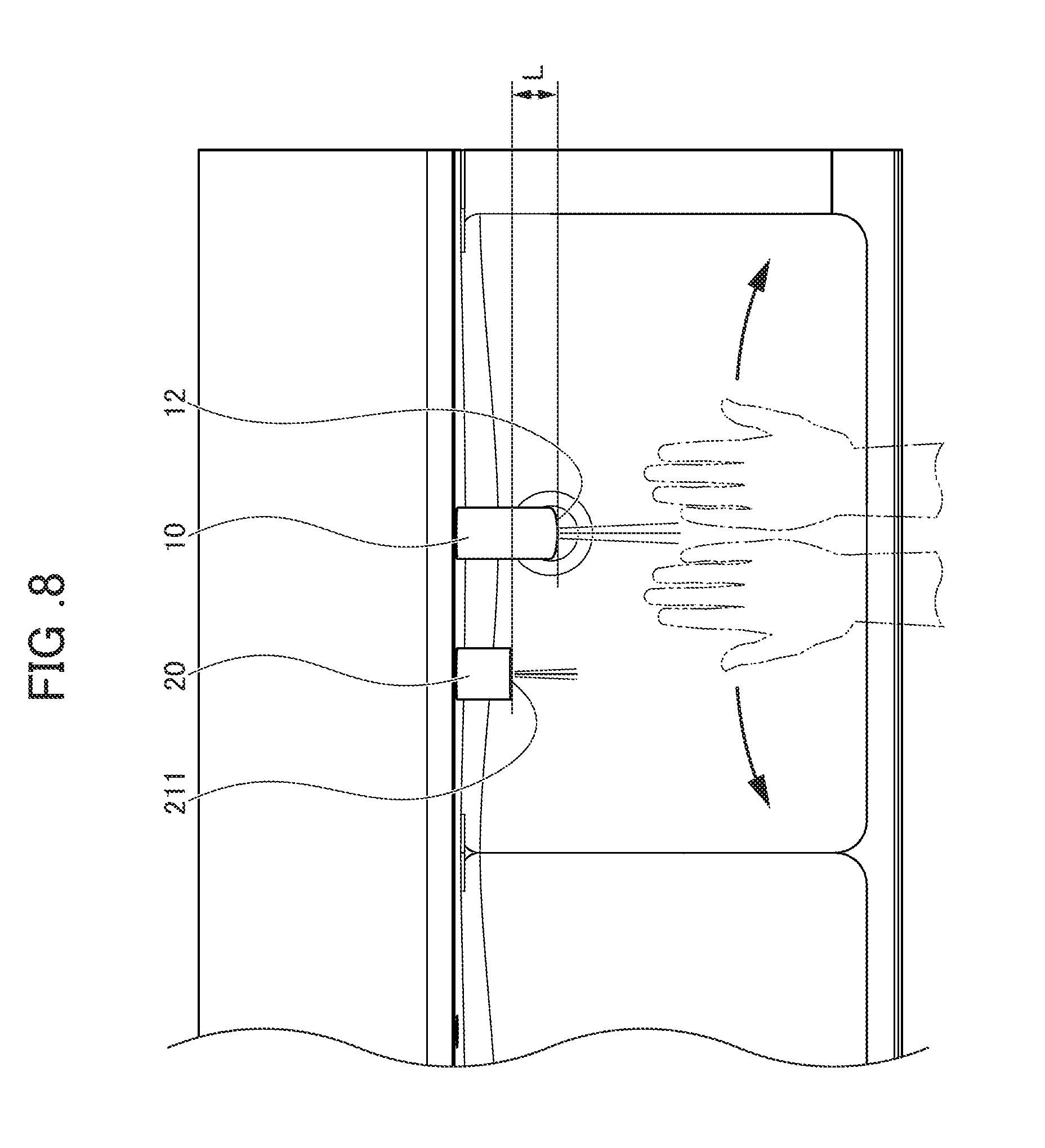
[0020] FIG. 8 is a diagram schematically illustrating the range of a hand movement and the range of a washing liquid dispensing sensor during a water discharger operation of the hand washing device according to the embodiment.
PREFERRED MODE FOR CARRYING OUT THE INVENTION
[0021] Hereinafter, an embodiment of the present invention will be described with reference to accompanying drawings. Incidentally, the present invention is not limited to the following embodiment. A hand washing device according to the present embodiment is installed in a toilet or a washroom in a public facility such as a train station, detects an object such as a human hand with a sensor, and is provided with a water discharger automatically discharging water and a washing liquid dispenser automatically dispensing a washing liquid such as water soap on the basis of a detection signal thereof.
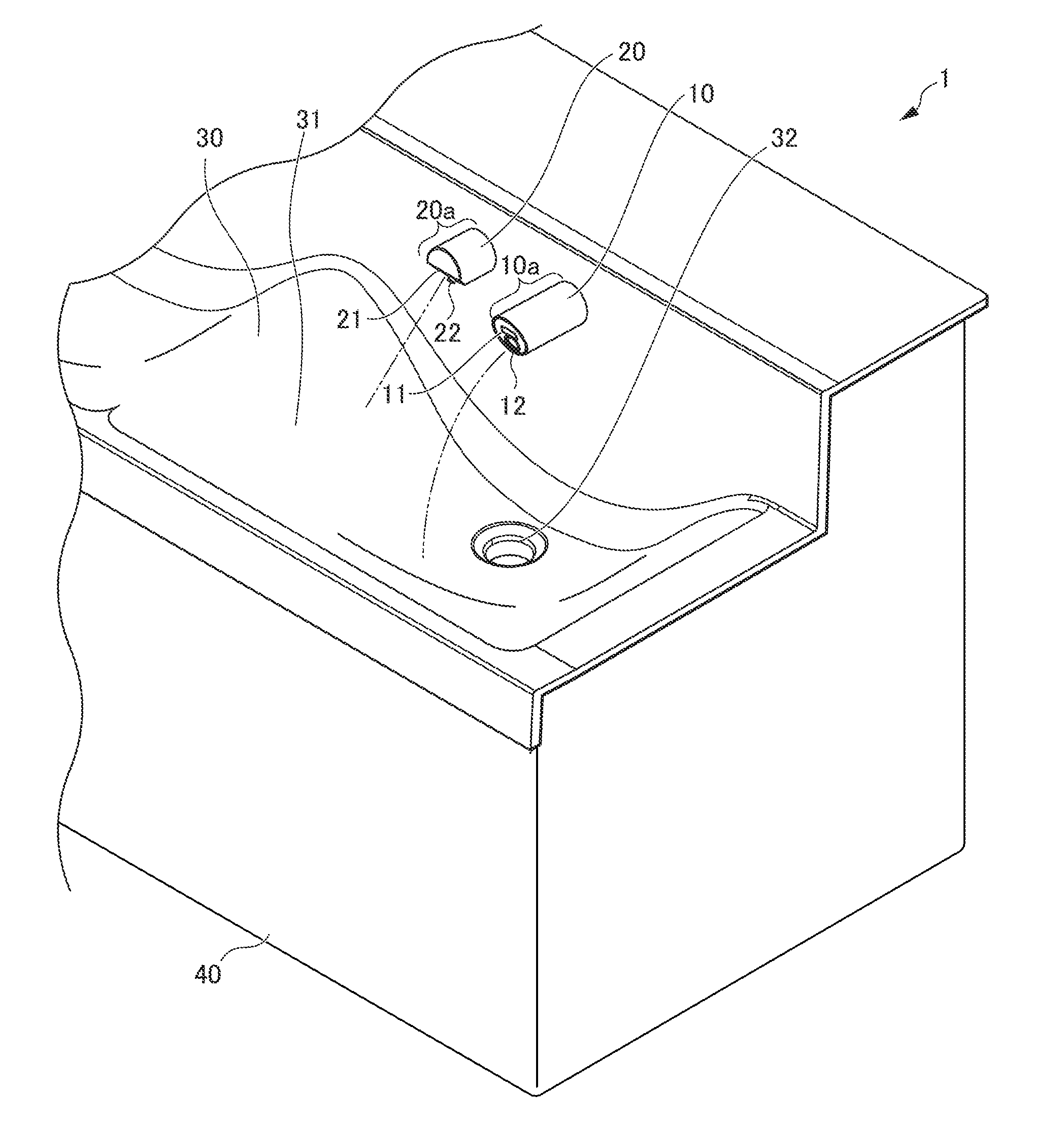
[0022] FIG. 1 is an overall perspective view of a hand washing device 1 according to an embodiment of the present invention. As illustrated in FIG. 1, the hand washing device 1 according to the present embodiment is provided with a water discharger 10, a washing liquid dispenser 20, a bowl 30, and a stand 40. In addition, the hand washing device 1 according to the present embodiment is one of a plurality of hand washing devices of the same type installed in parallel.
[0023] The water discharger 10 has an object-detecting water discharge sensor 11 and a water discharge port 12 on the tip side of a water discharger main body 10a. The water discharger 10 automatically discharges water (or hot water) from the water discharge port 12 once an object such as a human hand is detected by the water discharge sensor 11 by the object entering the detection range of the water discharge sensor 11.
[0024] The washing liquid dispenser 20 has an object-detecting washing liquid dispensing sensor 21 and a dispensing port 22 on the tip side of a washing liquid dispenser main body 20a. The washing liquid dispenser 20 automatically dispenses a washing liquid such as water soap from the dispensing port 22 once an object such as a human hand is detected by the washing liquid dispensing sensor 21 by the object entering the detection range of the washing liquid dispensing sensor 21.
[0025] The bowl 30 receives and discharges the water discharged from the water discharging device 10 and used for hand washing and the washing liquid such as water soap dispensed from the washing liquid dispensing device 20 and used for hand washing. A bowl portion main body 31 is formed on the upper surface of the bowl 30, and a drain port 32 is formed in the recess in the middle of the bowl portion main body 31. The drain port 32 communicates with a drain pipe (not illustrated). The water and the washing liquid used for hand washing and discharged to the bowl 30 are guided to the drain port 32 and discharged to the outside such as a sewer system through the drain pipe from the drain port 32.
[0026] The stand 40 is disposed below the bowl 30 and covers facility equipment such as the drain pipe (not illustrated) and other piping. The stand 40 prevents the inner portion of the stand 40 from being visible and the facility equipment disposed in the stand 40 from being touched.
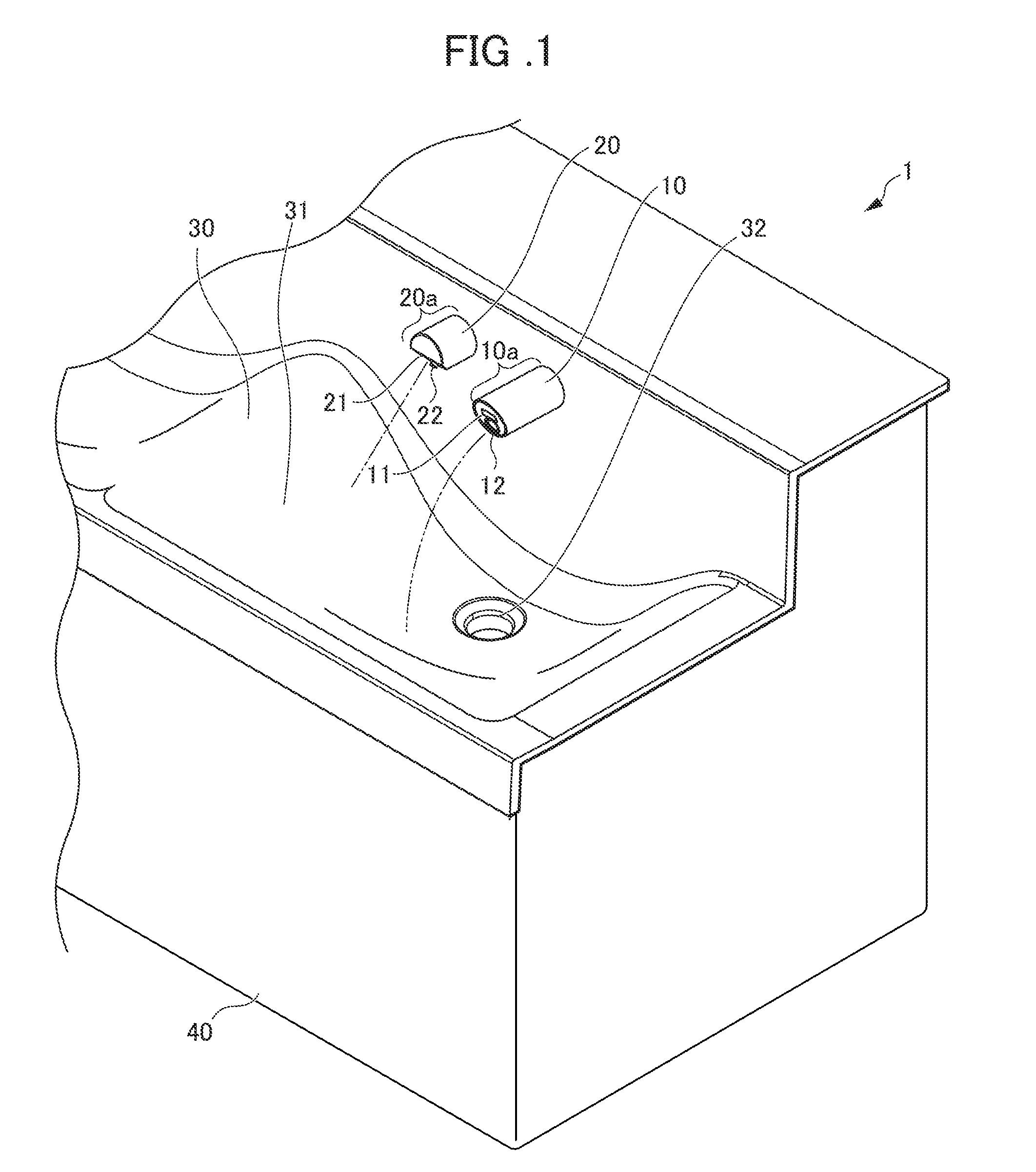
[0027] FIG. 2 is a block diagram illustrating a function of the water discharger 10 according to the present embodiment. The configuration of the water discharger 10 according to the present embodiment will be described below with reference to FIG. 2.
[0028] As illustrated in FIG. 2, the water discharger 10 is provided with a water supply pipe 13, a water discharge control unit 16, and the water discharger main body 10a that is provided, on the tip side, with the water discharge port 12 and the water discharge sensor 11 detecting an object such as a human hand.
[0029] The water discharge sensor 11 is a sensor detecting an object such as a human hand. The water discharge sensor 11 is an infrared sensor, a photoelectric sensor, a radio wave sensor, or the like. In the present embodiment, an infrared distance measurement sensor that has a light emitting portion and a light receiving portion is preferably used as the water discharge sensor 11. The infrared distance measurement sensor detects whether or not a detected object is present within a predetermined detection area by emitting light from the light emitting portion and receiving, with the light receiving portion, the reflected light from the detected object such as a human hand that results from the emitted light. The water discharge sensor 11 is electrically connected to the water discharge control unit 16 (described below). The water discharge sensor 11 transmits a detection signal to the water discharge control unit 16 (described below) once an object is detected.
[0030] The water discharge port 12 is connected to the water supply pipe 13 via the inner portion of the water discharger 10 and discharges water by being supplied with water from the water supply pipe 13.
[0031] The water supply pipe 13 is a path through which water supplied to the water discharger 10 circulates. The downstream side end portion of the water supply pipe 13 is connected to the water discharger 10, and the upstream side end portion of the water supply pipe 13 is connected to an external water supply source (not illustrated) such as a water supply system. In addition, an electromagnetic valve 15 is disposed on the water supply pipe 13. The electromagnetic valve 15 is electrically connected to the water discharge control unit 16 (described below) and switches between water discharge and cutoff by the water discharger 10 by performing an opening and closing operation in accordance with a control signal from the water discharge control unit 16. In addition, a hot water supply pipe 14 through which hot water circulates is connected to the water supply pipe 13 via the electromagnetic valve 15. The temperature of the discharged water is adjusted by hot water mixing ratio adjustment at the electromagnetic valve 15.
[0032] A circuit board on which a microcomputer or the like is mounted constitutes the water discharge control unit 16. The water discharge control unit 16 controls the discharge/cutoff by the water discharger 10 by transmitting a control signal to the electromagnetic valve 15 on the basis of a detection signal from the water discharge sensor 11 and opening and closing the electromagnetic valve 15.
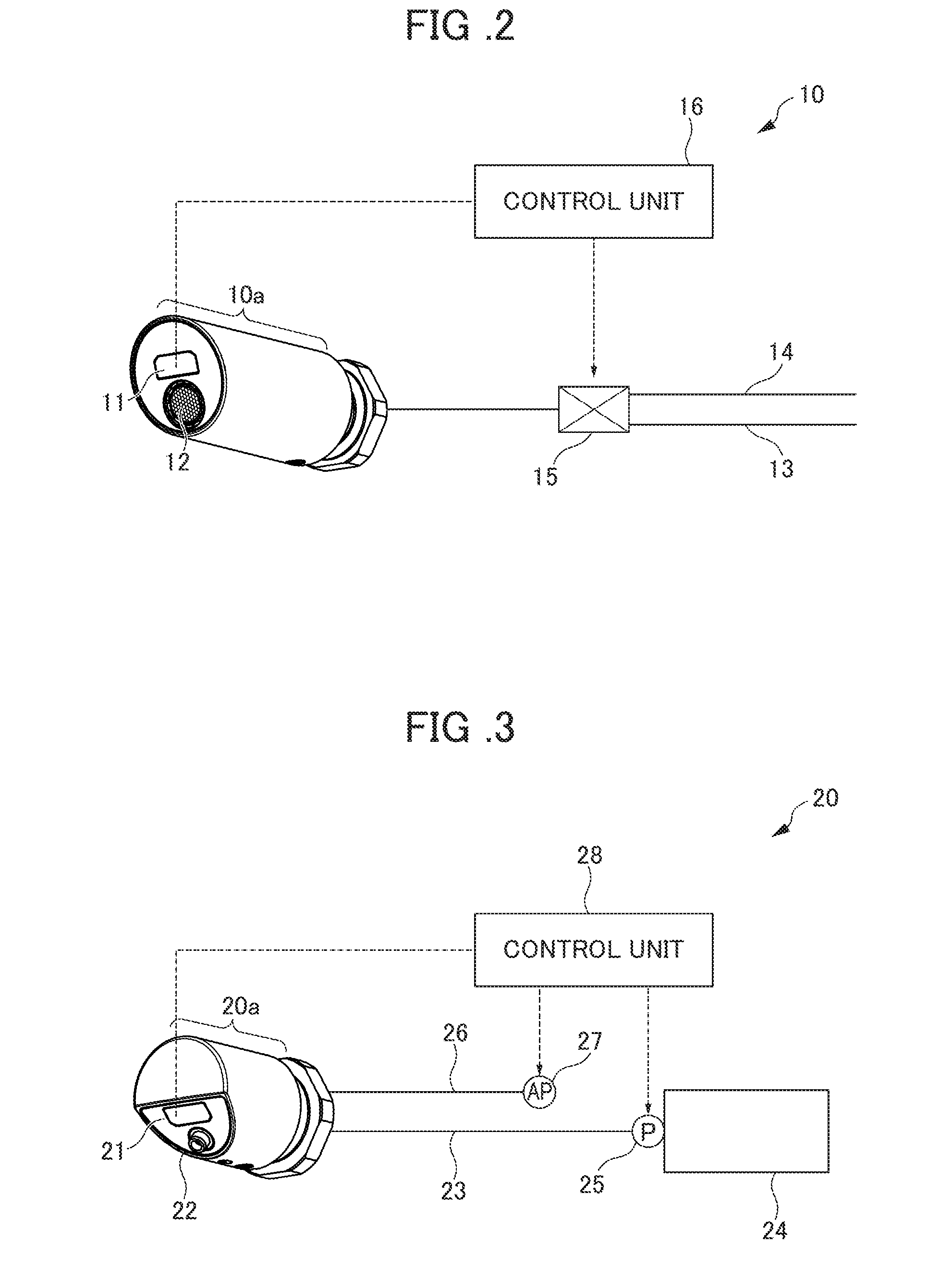
[0033] FIG. 3 is a block diagram illustrating a function of the washing liquid dispenser 20 according to the present embodiment. The configuration of the washing liquid dispenser 20 according to the present embodiment will be described below with reference to FIG. 3.
[0034] The washing liquid dispenser 20 has a washing liquid supply pipe 23, an air supply pipe 26, and the washing liquid dispenser main body 20a that is provided, on the tip side, with the dispensing port 22 and the washing liquid dispensing sensor 21 detecting an object such as a human hand.
[0035] As is the case with the water discharge sensor 11, the washing liquid dispensing sensor 21 is a sensor detecting an object such as a human hand, the washing liquid dispensing sensor 21 is an infrared sensor, a photoelectric sensor, a radio wave sensor, or the like, and an infrared distance measurement sensor that has a light emitting portion and a light receiving portion is preferably used as the washing liquid dispensing sensor 21. The washing liquid dispensing sensor 21 is electrically connected to a washing liquid dispensing control unit 28 (described below). The washing liquid dispensing sensor 21 transmits a detection signal to the washing liquid dispensing control unit 28 once an object is detected.
[0036] The dispensing port 22 is a member connected to the discharge port of the washing liquid dispenser 20 and dispenses, from the tip portion, bubbles formed by the washing liquid and air being mixed with each other.
[0037] The washing liquid supply pipe 23 is a pipe through which the washing liquid such as water soap circulates. The downstream side end portion of the washing liquid supply pipe 23 is connected to the washing liquid dispenser main body 20a, and the upstream side end portion of the washing liquid supply pipe 23 is connected to a washing liquid tank 24 storing the washing liquid. Incidentally, although the washing liquid tank 24 is connected to the single washing liquid dispenser main body 20a in FIG. 3, the washing liquid tank 24 is actually connected to a plurality of washing liquid dispenser main bodies for public use. In addition, a washing liquid pump 25 is connected to the washing liquid supply pipe 23. The washing liquid pump 25 is electrically connected to the washing liquid dispensing control unit 28 (described below) and supplies the washing liquid dispenser main body 20a, by pumping, with the washing liquid such as water soap stored in the washing liquid tank 24 on the basis of a control signal transmitted from the washing liquid dispensing control unit 28.
[0038] The air supply pipe 26 is a pipe through which air for washing liquid bubble formation is supplied to the washing liquid dispenser main body 20a. The downstream side end portion of the air supply pipe 26 is connected to the washing liquid dispenser main body 20a, and the upstream side end portion of the air supply pipe 26 is connected to an air pump 27. The air pump 27 has a drive unit such as a motor, and compresses outside air and discharges the air to the downstream side by the drive unit being driven. The air pump 27 is electrically connected to the washing liquid dispensing control unit 28 (described below), and supplies the air to the washing liquid dispenser main body 20a on the basis of a control signal transmitted from the washing liquid dispensing control unit 28.
[0039] A circuit board on which a microcomputer or the like is mounted constitutes the washing liquid dispensing control unit 28. The washing liquid dispensing control unit 28 performs control to operate the washing liquid pump 25 and the air pump 27 for a predetermined time once a detection signal is received from the washing liquid dispensing sensor 21 and then non-operate the washing liquid pump 25 and the air pump 27, even in the event of detection signal reception from the washing liquid dispensing sensor 21, for a certain period of time. Incidentally, the washing liquid dispensing control unit 28 controlling the washing liquid dispenser 20 is independently disposed separately from the water discharge control unit 16 controlling the water discharger 10.
[0040] The positional relationship of the water discharger 10 and the washing liquid dispenser 20 of the hand washing device 1 according to the present embodiment will be described below. FIG. 4 is a diagram illustrating a discharge angle and a sensor angle, which are the inclination angles of sensor directions X1 and Y2 and discharge directions X1a and Y2a of the water discharger 10 and the washing liquid dispenser 20 with respect to the horizontal direction, respectively. Incidentally, the discharge directions X1a and Y2a mentioned above indicate directions immediately after water or washing liquid discharge from each device and do not take into account the effect of gravity on the discharged water and washing liquid. Specifically, the discharge directions X1a and Y2a are the extension directions of the respective dispensing ports. Likewise, the sensor direction indicates the direction immediately after emission of emission light such as infrared light from the device and does not take into account the effect of, for example, diffusion and scattering on the emission light.
[0041] As illustrated in FIG. 4, the sensor directions X1 and Y2 and the discharge directions X1a and Y2a of the water discharger 10 and the washing liquid dispenser 20 are inclined downward with respect to the horizontal direction and a water discharge angle R1a of the water discharger 10 is less than a sensor angle R2 of the washing liquid dispenser 20. In other words, the sensor direction Y2 of the washing liquid dispenser 20 is inclined further downward than the discharge direction X1a of the water discharger 10.
[0042] In the present embodiment, a person's hand is unlikely to enter the detection range of the washing liquid dispensing sensor 21 when the person performs a water discharge operation on the water discharger 10 by the angular difference between the water discharge angle R1a of the water discharger 10 and the sensor angle R2 of the washing liquid dispenser 20 being equal to or greater than 10.degree.. In addition, a human hand becomes less likely to enter the sensor range of the washing liquid dispensing sensor 21 during a water discharge operation as the sensor angle R2 of the washing liquid dispenser 20 increases, that is, as the angular difference from the water discharge angle R1a of the water discharger 10 increases by the sensor direction facing downward. In a case where the angular difference between R1a and R2 exceeds 40.degree., a person should stretch his or her hand to the back side to the point of coming into contact with the wall to perform a dispensing operation on the washing liquid dispenser 20, which is not preferable because this results in a decline in the usability of the washing liquid dispenser 20. Accordingly, the angular difference between R1a and R2 is preferably 10.degree. to 40.degree..
[0043] In addition, it is preferable that the water discharge angle R1a of the water discharger 10 is 10.degree. to 30.degree. and the sensor angle R2 of the washing liquid dispenser 20 is 30.degree. to 50.degree.. In the present embodiment, R1a is 20.degree. and R2 is 45.degree.. Incidentally, in the present embodiment, a sensor angle R1 and the water discharge angle R1a of the water discharger 10 are almost equal to each other and the sensor angle R2 and a discharge angle R2a of the washing liquid dispenser 20 are almost equal to each other.
[0044] The internal structures of the water discharger main body 10a and the washing liquid dispenser main body 20a according to the present embodiment will be described in detail below with reference to FIGS. 5 and 6.
[0045] FIG. 5 is a longitudinal sectional view of the water discharger 10 according to the present embodiment. As illustrated in FIG. 5, the water discharger 10 is provided with the water discharge sensor 11, the water discharge port 12, the water supply pipe 13, water discharger fixing members 131 and 132, and a water discharger main body case 133.
[0046] The water discharge sensor 11 is an infrared distance measurement sensor as described above and has a substantially rectangular parallelepiped shape. The water discharge sensor 11 is provided with a water discharge sensor emission portion 111 at the tip and is accommodated in a water discharge sensor accommodating portion 134 disposed in the water discharger main body case 133 (described below). In a state where the water discharge sensor 11 is accommodated in the water discharge sensor accommodating portion 134, the water discharge sensor emission portion 111 is the only part of the water discharge sensor 11 that is exposed to the outside.
[0047] The water discharge port 12 has a water discharge portion 121 that has an extension direction substantially perpendicular to an inclined surface portion 133a of the water discharger main body case 133 (described below) and is connected to the water supply pipe 13 in the water discharger main body 10a. Accordingly, the discharge direction X1a of the water that is discharged from the water discharge port 12 is substantially perpendicular to the inclined surface portion 133a, that is, the tip surface of the water discharge portion 121.
[0048] The water supply pipe 13 is a metallic or resinous member such as a hose supplying water or hot water to the water discharging device main body 10a. The downstream side end portion of the water supply pipe 13 is connected to the water discharge port 12.
[0049] The water discharger fixing members 131 and 132 include a water discharger fixing member main body 131 that has a cylindrical portion and a flange portion and a nut 132 that can be screwed therewith. The water discharger main body 10a is fixed to a wall W by the wall W being pinched between the nut 132 and the flange portion of the water discharger fixing member main body 131 and the water discharger fixing member main body 131 and the nut 132 being tightened by screwing.
[0050] The water discharger main body case 133 is a substantially cylindrical metal member that has the inclined surface portion 133a in the tip portion, and covers and accommodates therein a member disposed on the front side with respect to an attachment surface W1. A proximal end portion 133b and the inclined surface portion 133a in the tip portion of the water discharger main body case 133 are open. The water discharge sensor emission portion 111 and the water discharge portion 121 formed at the tip of the water discharge port 12 are exposed from the inclined surface portion 133a. The proximal end portion 133b abuts against the attachment surface W1. In addition, the water discharge sensor accommodating portion 134 is disposed in the water discharger main body case 133. The water discharge sensor accommodating portion 134 is formed to be open in the inclined surface portion 133a and has a recessed shape that is almost identical in shape and size to the water discharge sensor 11. The water discharge sensor accommodating portion 134 is inclined upward from the inclined surface portion 133a toward the proximal end side. The sensor direction X1 from the water discharge sensor 11 accommodated in the water discharge sensor accommodating portion 134 is substantially perpendicular to the inclined surface portion 133a, that is, the surface of the water discharge sensor emission portion 111.
[0051] FIG. 6 is a longitudinal sectional view of the washing liquid dispenser 20 according to the present embodiment. As illustrated in FIG. 6, the washing liquid dispenser 20 has the washing liquid dispensing sensor 21, the dispensing port 22, a dispensing port member 221, a connecting member 223, dispenser fixing members 224 and 225, and a dispenser main body case 226.
[0052] The washing liquid dispensing sensor 21 is an infrared distance measurement sensor as described above and has a substantially rectangular parallelepiped shape. The washing liquid dispensing sensor 21 is provided with an emission portion 211 at the tip and is accommodated in a washing liquid dispensing sensor accommodating portion 212 disposed in the dispensing port member 221 (described below). In a state where the washing liquid dispensing sensor 21 is accommodated in the washing liquid dispensing sensor accommodating portion 212, the emission portion 211 is the only part of the washing liquid dispensing sensor 21 that is exposed to the outside.
[0053] The dispensing port 22 is connected to a flow passage 222 formed in the dispensing port member 221 (described below) and has an extension direction substantially perpendicular to an inclined surface portion 226a formed in the washing liquid dispenser main body case 226 (described below). Accordingly, the discharge direction Y2a of the washing liquid that is dispensed from the dispensing port 22 is substantially perpendicular to the inclined surface portion 226a, that is, the tip surface of the dispensing port 22.
[0054] The dispensing port member 221 is connected to the dispensing port 22 and has the washing liquid flow passage 222 therein. In addition, the dispensing port member 221 is a resinous member that has the washing liquid dispensing sensor accommodating portion 212 holding the washing liquid dispensing sensor 21. The washing liquid dispensing sensor accommodating portion 212 is formed to be open in the inclined surface portion 226a (described below) and has a recessed shape that is almost identical in shape and size to the washing liquid dispensing sensor 21. The washing liquid dispensing sensor accommodating portion 212 is inclined upward from the inclined surface portion 226a toward the proximal end side. The sensor direction Y2 from the washing liquid dispensing sensor 21 accommodated in the washing liquid dispensing sensor accommodating portion 212 is substantially perpendicular to the inclined surface portion 226a, that is, the surface of the emission portion 211. Incidentally, the inclination angle of the surface of the emission portion 211 may be greater than the inclination angle of the tip surface of the water discharge portion 121. In addition, the dispensing port member 221 is connected to the connecting member 223 (described below).
[0055] The connecting member 223 is a resinous member that has a washing liquid and air flow passage therein. The washing liquid supply pipe 23 and the air supply pipe 26 are connected to the upstream side of the connecting member 223, and the dispensing port member 221 is connected to the downstream side of the connecting member 223. Washing liquid bubbles are formed by the supplied washing liquid and air being mixed with each other in the connecting member 223.
[0056] The dispenser fixing members 224 and 225 include a dispenser fixing member main body 224 that has a cylindrical portion and a flange portion and a nut 225 that can be screwed therewith. The washing liquid dispenser main body 20a is fixed to the wall W by the wall W being pinched between the nut 225 and the flange portion of the dispenser fixing member main body 224 and the dispenser fixing member main body 224 and the nut 225 being tightened by screwing.
[0057] The dispenser main body case 226 is a substantially cylindrical metal member that has the inclined surface portion 226a in the tip portion, and covers and accommodates therein a member disposed on the front side with respect to the attachment surface W1. A proximal end portion 226b and the inclined surface portion 226a in the tip portion of the dispenser main body case 226 are open. The emission portion 211 and the dispensing port 22 are exposed from the inclined surface portion 226a. The proximal end portion 226b abuts against the attachment surface W1.
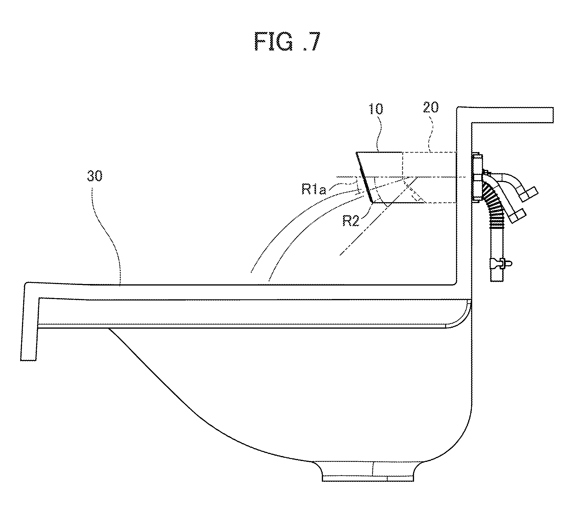
[0058] FIG. 7 is a diagram schematically illustrating the discharge direction X1a of the water discharger 10 and the sensor direction Y2 of the washing liquid dispenser 20 in a case where the angular difference between the water discharge angle R1a of the water discharger 10 and the sensor angle R2 of the washing liquid dispenser 20 is 10.degree. to 40.degree.. As illustrated in FIG. 7, an adequate space can be provided between a hand washing position and the position of detection by the washing liquid dispensing sensor 21 and a human hand is unlikely to enter the detection range of the washing liquid dispensing sensor 21 during hand washing by the angular difference between R1a and R2 being 10.degree. to 40.degree..
[0059] FIG. 8 is a schematic diagram illustrating a state where the emission portion 211 of the washing liquid dispensing sensor 21 is disposed closer to the back side by a distance L than the water discharge port 12 of the water discharger 10 in the hand washing device 1 according to the present embodiment.
[0060] In the present embodiment, the emission portion 211 disposed on the tip side of the washing liquid dispensing sensor 21 and emitting emission light such as infrared light is disposed closer to the back side than the water discharge port 12 of the water discharger 10. As described above, a human hand becomes less likely to enter the detection range of the washing liquid dispensing sensor 21 during hand washing as the angular difference between R1a and R2 increases, that is, as the sensor angle R2 of the washing liquid dispensing sensor 21 increases. Still, an excessively large R2 is not preferable in ensuring the usability of the washing liquid dispenser 20. However, by the emission portion 211 being disposed closer to the back side than the water discharge port 12, a human hand is unlikely to enter the detection range of the washing liquid dispensing sensor 21 during hand washing even without an excessive increase in R2, that is, even in a case where the angular difference between R1a and R2 is relatively small.
[0061] FIG. 8 is a diagram schematically illustrating the movement range of a person's hand, the discharge direction X1a of the water discharger 10, and the detection range of the washing liquid dispensing sensor 21 at a time when he or she performs a water discharge operation on the water discharger 10. Incidentally, in FIG. 8, the angular difference between the water discharge angle R1a of the water discharger 10 and the sensor angle R2 of the washing liquid dispenser 20 is 10.degree. to 40.degree.. As illustrated in FIG. 8, by the emission portion 211 being disposed closer to the back side than the water discharge port 12, the movement range of the hand and the detection range of the washing liquid dispensing sensor 21 are unlikely to overlap each other when he or she performs the water discharge operation on the water discharger 10. Incidentally, it is preferable that the distance L has a range of at least 40 mm.
[0062] An operation of the water discharger 10 according to the present embodiment will be described below with reference to FIG. 2. Once a person's hand enters the detection range of the water discharge sensor 11 by approaching the water discharger main body 10a, a detection signal is transmitted to the water discharge control unit 16 by the water discharge sensor 11. After receiving the detection signal, the water discharge control unit 16 transmits a control signal to the electromagnetic valve 15. After receiving the control signal, the electromagnetic valve 15 performs a valve opening operation and supplies water to the water discharger main body 10a. The water supplied to the water discharger main body 10a is discharged from the water discharge port 12. Likewise, a control signal is transmitted to the electromagnetic valve 15 by the water discharge control unit 16, with a detection signal from the water discharge sensor 11 received by the water discharge control unit 16, once the human hand disappears from the detection range of the water discharge sensor 11 after the person finishes washing his or her hand. Then, the electromagnetic valve 15 performs a valve closing operation and the water supplied to the water discharger main body 10a is blocked. As a result, the water discharged from the water discharge port 12 is cut off.
[0063] An operation of the washing liquid dispenser 20 according to the present embodiment will be described below with reference to FIG. 3. Once a person's hand enters the detection range of the washing liquid dispensing sensor 21 by approaching the washing liquid dispenser main body 20a, a detection signal is transmitted to the washing liquid dispensing control unit 28 by the washing liquid dispensing sensor 21. After receiving the detection signal, the washing liquid dispensing control unit 28 transmits a control signal to the washing liquid pump 25 and the air pump 27. After receiving the control signal, the washing liquid pump 25 supplies the washing liquid stored in the washing liquid tank 24, by pumping, to the washing liquid dispenser main body 20a through the washing liquid supply pipe 23. Likewise, after receiving the control signal, the air pump 27 supplies air to the washing liquid dispenser main body 20a through the air supply pipe 26. The washing liquid and the air supplied to the washing liquid dispenser main body 20a are mixed with each other and discharged in the form of bubbles from the tip of the dispensing port 22 connected to the discharge port.
[0064] The hand washing device 1 according to the present embodiment described above has the following effects. The hand washing device 1 according to the present embodiment is configured such that the sensor direction Y2 of the washing liquid dispensing sensor 21 of the washing liquid dispenser 20 is inclined further downward than the discharge direction X1a of water or hot water discharged from the water discharge port 12 of the water discharger 10. As a result, a person's hand is unlikely to enter the detection range of the washing liquid dispensing sensor 21 when he or she performs a water discharge operation on the water discharger 10, that is, during hand washing, and thus malfunctions of the washing liquid dispenser 20 during hand washing can be prevented. In addition, it is possible for the detection ranges of the respective sensors of the water discharger 10 and the washing liquid dispenser 20 not to overlap each other, and thus the devices can be individually controlled and control units can be individually disposed. In addition, cost reduction can be achieved as malfunctions can be prevented with a simple device structure.
[0065] In addition, the hand washing device 1 according to the present embodiment is configured such that the emission portion 211, from which emission light from the washing liquid dispensing sensor 21 is emitted, is disposed closer to the back side than the water discharge port 12 of the water discharger 10. As a result, a human hand is unlikely to enter the detection range of the washing liquid dispensing sensor 21 during hand washing even without an excessive downward inclination of the sensor direction of the washing liquid dispensing sensor 21, and thus malfunctions of the washing liquid dispenser 20 during hand washing can be prevented with the usability of the washing liquid dispenser 20 ensured.
[0066] In addition, the hand washing device 1 according to the present embodiment is configured such that the angular difference between R2 and R1a is 10.degree. to 40.degree. in a case where the inclination angle of the sensor direction of the washing liquid dispenser 20 with respect to the horizontal direction is R2 and the inclination angle of the discharge direction X1a of the water discharger 10 with respect to the horizontal direction is R1a. As a result, a human hand entering the detection range of the washing liquid dispensing sensor 21 during hand washing can be more reliably prevented, and thus malfunctions of the washing liquid dispenser 20 during hand washing can be more reliably prevented.
[0067] In addition, in the hand washing device 1 according to the present embodiment, the water discharge control unit 16 controlling the water discharger 10 and the washing liquid dispensing control unit 28 controlling the washing liquid dispenser 20 are individually disposed. As a result, the control units do not have to be replaced altogether even in a case where a new device is added to the hand washing device 1 and in a case where one of the devices is repaired, and thus facility expansion and repair costs can be reduced.
[0068] In addition, the present invention is not limited to the above-described embodiment, and any modification, improvement, and so on is included in the present invention insofar as the object of the present invention can be achieved. For example, although the water discharger 10 and the washing liquid dispenser 20 of the hand washing device 1 according to the present embodiment are fixed and attached to a wall in FIG. 1, the present invention is not limited thereto. Alternatively, the water discharger 10 and the washing liquid dispenser 20 may be fixed and attached to a stand.
[0069] In addition, although a plurality of the washing liquid dispensing device 20 are configured to receive washing liquid supply from the single washing liquid tank 24 in the above-described embodiment, the present invention is not limited thereto. Alternatively, a single washing liquid dispensing device may be configured to receive washing liquid supply from a single washing liquid tank.
[0070] In addition, although the washing liquid dispensing device 20 is provided with the air supply pipe 26 supplying air for washing liquid bubble formation in the above-described embodiment, the present invention is not limited thereto. Alternatively, the washing liquid dispensing device 20 may not be provided with the air supply pipe 26.
EXPLANATION OF REFERENCE NUMERALS
[0071] 1 Hand washing device [0072] 10 Water discharger [0073] 11 Water discharge sensor [0074] 12 Water discharge port [0075] 16 Water discharge control unit [0076] 20 Washing liquid dispenser [0077] 21 Washing liquid dispensing sensor [0078] 22 Dispensing port [0079] 28 Washing liquid dispensing control unit
* * * * *
D00000
D00001
D00002
D00003
D00004
D00005
D00006
D00007
XML
uspto.report is an independent third-party trademark research tool that is not affiliated, endorsed, or sponsored by the United States Patent and Trademark Office (USPTO) or any other governmental organization. The information provided by uspto.report is based on publicly available data at the time of writing and is intended for informational purposes only.
While we strive to provide accurate and up-to-date information, we do not guarantee the accuracy, completeness, reliability, or suitability of the information displayed on this site. The use of this site is at your own risk. Any reliance you place on such information is therefore strictly at your own risk.
All official trademark data, including owner information, should be verified by visiting the official USPTO website at www.uspto.gov. This site is not intended to replace professional legal advice and should not be used as a substitute for consulting with a legal professional who is knowledgeable about trademark law.