Heat Spreading Cloths
Pidwerbecki; David ; et al.
U.S. patent application number 15/860553 was filed with the patent office on 2019-02-07 for heat spreading cloths. This patent application is currently assigned to Intel Corporation. The applicant listed for this patent is Intel Corporation. Invention is credited to Mark MacDonald, David Pidwerbecki.
| Application Number | 20190040554 15/860553 |
| Document ID | / |
| Family ID | 65229196 |
| Filed Date | 2019-02-07 |


View All Diagrams
| United States Patent Application | 20190040554 |
| Kind Code | A1 |
| Pidwerbecki; David ; et al. | February 7, 2019 |
HEAT SPREADING CLOTHS
Abstract
Heat spreading cloths, associated devices, systems, and methods can include a plurality of attached polymeric fibers that are thermally conductive and electrically insulative. The heat spreading cloth can be configured to couple an electronic component thereto in a heat spreading relationship.
| Inventors: | Pidwerbecki; David; (Hillsboro, OR) ; MacDonald; Mark; (Beaverton, OR) | ||||||||||
| Applicant: |
|
||||||||||
|---|---|---|---|---|---|---|---|---|---|---|---|
| Assignee: | Intel Corporation Santa Clara CA |
||||||||||
| Family ID: | 65229196 | ||||||||||
| Appl. No.: | 15/860553 | ||||||||||
| Filed: | January 2, 2018 |
| Current U.S. Class: | 1/1 |
| Current CPC Class: | D03D 1/00 20130101; D03D 2700/017 20130101; D03D 1/0088 20130101; G06F 1/203 20130101; A41D 1/002 20130101 |
| International Class: | D03D 1/00 20060101 D03D001/00 |
Claims
1. A heat spreading cloth, comprising: a plurality of attached polymeric fibers, said polymeric fibers being thermally conductive and electrically insulative; and an electronics area configured to thermally couple to an electronic device in a heat spreading relationship.
2. The heat spreading cloth of claim 1, wherein the plurality of polymeric fibers includes a thermoplastic polymeric fiber.
3. The heat spreading cloth of claim 2, wherein the thermoplastic polymer fiber includes polyamide, polybenzimidazole, polycarbonate, polyethylene, polypropylene, polyvinyl chloride, or a combination thereof.
4. The heat spreading cloth of claim 1, wherein the plurality of polymeric fibers includes aligned polymeric fibers having a high degree of molecular alignment to provide the aligned polymeric fibers with a thermal conductivity of at least 10 times the thermal conductivity of the unaligned polymeric fibers.
5. The heat spreading cloth of claim 1, wherein the polymeric fibers have a linear mass density of from 10 denier to 6000 denier.
6. The heat spreading cloth of claim 1, wherein the polymeric fibers are attached by interweaving the polymeric fibers.
7. The heat spreading cloth of claim 1, further comprising a plurality of carrier fibers.
8. The heat spreading cloth of claim 7, wherein the carrier fibers are either natural fibers or synthetic fibers.
9. The heat spreading cloth of claim 7, wherein the plurality of polymeric fibers comprises at least 20 wt % of the heat spreading cloth.
10. The heat spreading cloth of claim 1, wherein the polymeric fibers are attached by fusing a portion of the plurality of polymeric fibers together or to a carrier fiber.
11. The heat spreading cloth of claim 1, wherein the polymeric fibers have a thermal conductivity of at least 5 watts per meter kelvin (W/m-K).
12. The heat spreading cloth of claim 1, wherein the polymeric fibers have a dielectric strength of at least 10 kV/cm.
13. The heat spreading cloth of claim 1, wherein the electronics area is marked for placement of an electronic device.
14. The heat spreading cloth of claim 1, wherein the electronics area is substantially free of a carrier fiber.
15. The heat spreading cloth of claim 1, wherein the electronics area includes carrier fiber in an amount from about 0 wt % to about 50 wt % of a carrier fiber.
16. The heat spreading cloth of claim 1, wherein the electronics area is an area having an effective heat spreading weave or orientation of the polymeric fibers.
17. The heat spreading cloth of claim 1, wherein the electronics area is an area of the heat spreading cloth including a polymeric material suitable for attachment of the electronic device thereto via sintering.
18. The heat spreading cloth of claim 1, wherein the electronics area is disposed at a perimeter of the heat spreading cloth.
19. The heat spreading cloth of claim 1, wherein the electronics area is disposed at a central location of the heat spreading cloth.
20. A method of manufacturing a heat spreading cloth, comprising: attaching a plurality of polymeric fibers, said polymeric fibers being thermally conductive and electrically insulative; and forming an electronics area of the heat spreading cloth, said electronics area being configured to thermally couple to an electronic device in a heat spreading relationship.
21. The method of claim 20, wherein attaching includes interweaving the polymeric fibers.
22. The method of claim 20, wherein attaching includes attaching the polymeric fibers to a plurality of carrier fibers.
23. The method of claim 20, wherein the plurality of polymeric fibers comprises at least 20 wt % of the heat spreading cloth.
24. The method of claim 20, wherein attaching includes fusing a portion of the plurality of polymeric fibers together or to a carrier fiber.
25. The method of claim 20, wherein forming includes preparing an effective heat spreading weave or orientation of the polymeric fibers.
26. The method of claim 20, wherein forming includes marking the electronics area for placement of the electronic device.
Description
BACKGROUND
[0001] Typical wearable technology or "wearables" includes and electronic device or component incorporated into an article or accessory that can be worn on a user's body. A growing number of uses have been found for such devices, including monitoring and reporting aspects of a user's physiology, monitoring and reporting aspects of a surrounding environment, participating in geographic location or tracking services, providing power or support for other electronic devices, security and authentication, and personal climate or comfort, among others. Among the many challenges that wearable technology can face is management of heat as a byproduct of the electronic device or component's operation. As with many other electronic devices, electronic components of a wearable device can face significant thermal management challenges which limit their size, operation, or degree to which they can be integrated into the wearable technology. As such, improved thermal solutions for electronic components in wearable devices continue to be sought.
BRIEF DESCRIPTION OF THE DRAWINGS
[0002] Features and advantages of the disclosure will be apparent from the detailed description which follows, taken in conjunction with the accompanying drawings, which together illustrate, by way of example, features of the disclosure; and, wherein:
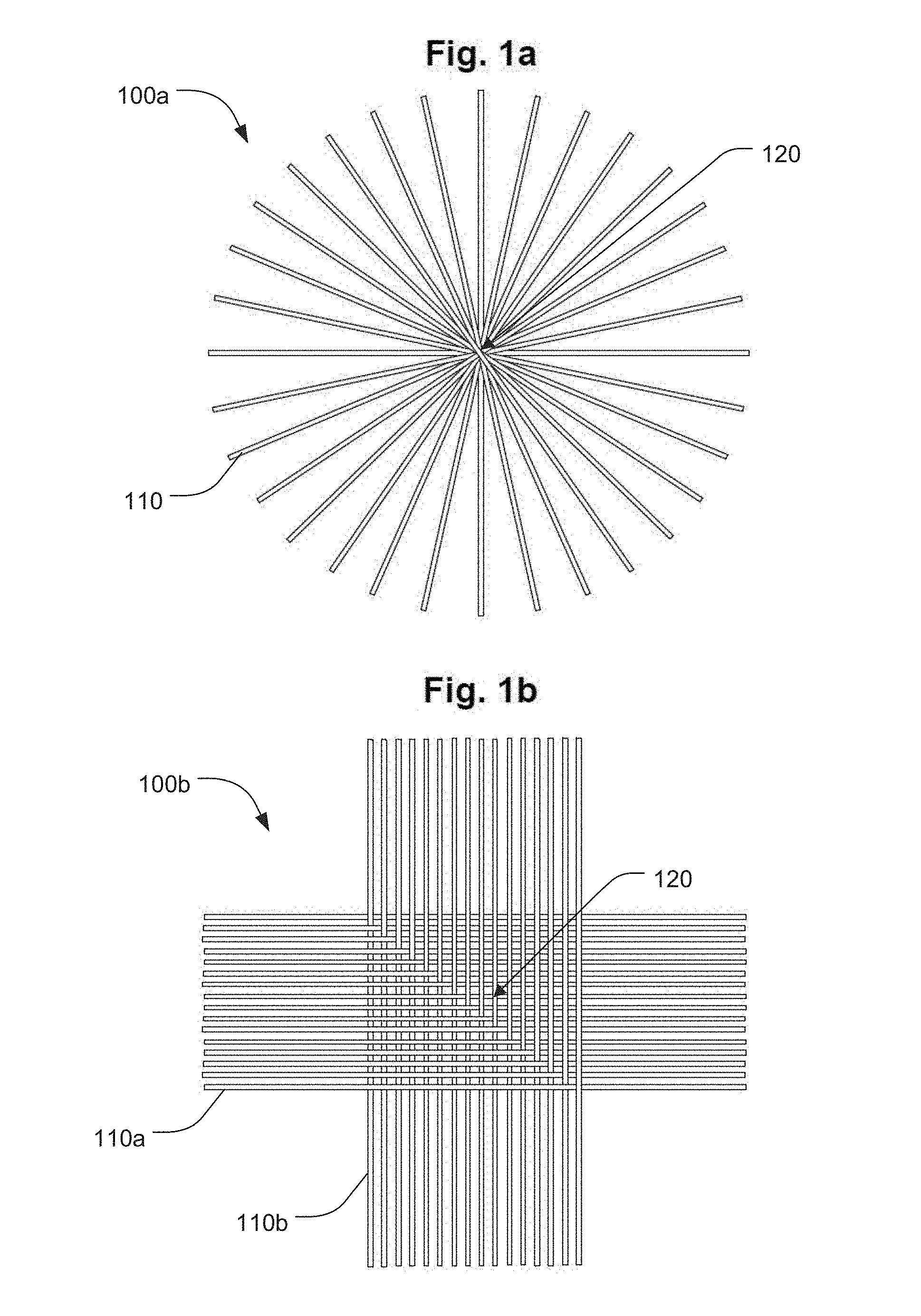
[0003] FIG. 1a illustrates a woven heat spreading cloth in accordance with an example embodiment;
[0004] FIG. 1b illustrates a woven heat spreading cloth in accordance with an example embodiment;
[0005] FIG. 1c illustrates a group of aligned polymeric fibers in accordance with an example embodiment;
[0006] FIG. 1d illustrates the plurality of aligned polymeric fibers of FIG. 1c after fusing the fibers together, in accordance with an example embodiment;
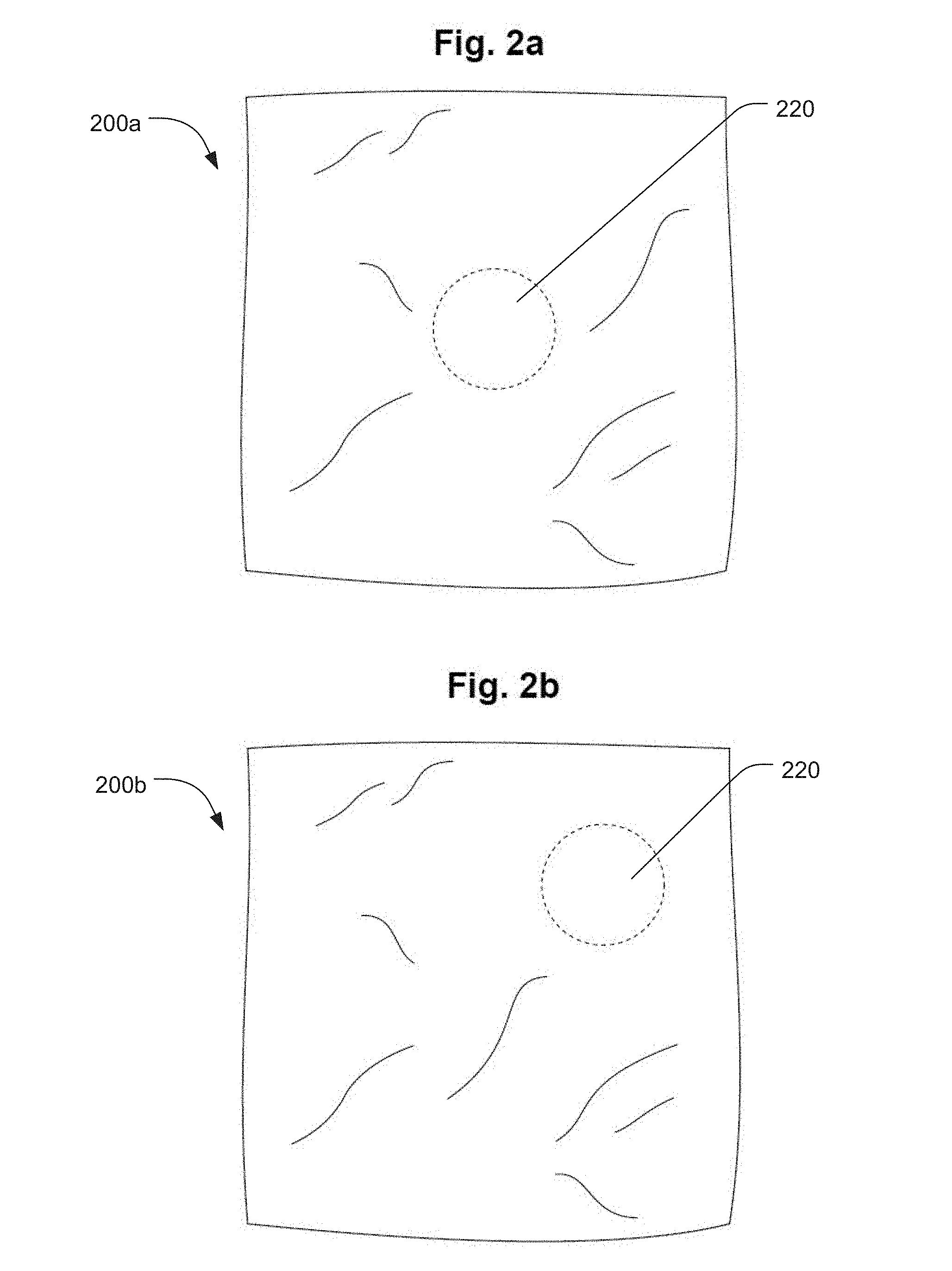
[0007] FIG. 2a illustrates a heat spreading cloth with an identified electronics area in a central location in accordance with an example embodiment;
[0008] FIG. 2b illustrates a heat spreading cloth with an identified electronics area in a peripheral location in accordance with an example embodiment;
[0009] FIG. 2c illustrates a heat spreading cloth with an identified electronics area in a central location and having a rectangular shape or pattern in accordance with an example embodiment;
[0010] FIG. 2d illustrates a heat spreading cloth with an identified electronics area in a central location and having an oval shape or pattern in accordance with an example embodiment;
[0011] FIG. 2e illustrates a heat spreading cloth with a plurality of identified electronics areas in accordance with an example embodiment;
[0012] FIG. 3a illustrates a top view of an electronic component in accordance with an example embodiment;
[0013] FIG. 3b illustrates a side view of the electronic component of FIG. 3a.
[0014] FIG. 3c illustrates a top view of a wearable electronic device in accordance with an example embodiment;
[0015] FIG. 3d illustrates a side view of the wearable electronic device of FIG. 3c;
[0016] FIG. 4a illustrates a top view of an electronic component in accordance an example embodiment;.
[0017] FIG. 4b illustrates a side view of the electronic component of FIG. 4a.
[0018] FIG. 4c illustrates a top view of a wearable electronic device in accordance with an example embodiment;
[0019] FIG. 4d illustrates a side view of the wearable electronic device of FIG. 4c.
[0020] FIG. 5a illustrates an electronic component and a component base in accordance with an example embodiment;
[0021] FIG. 5b illustrates a side view of a wearable electronic device in accordance with an example embodiment;
[0022] FIG. 5c illustrates a top view of the wearable electronic device of FIG. 5b.
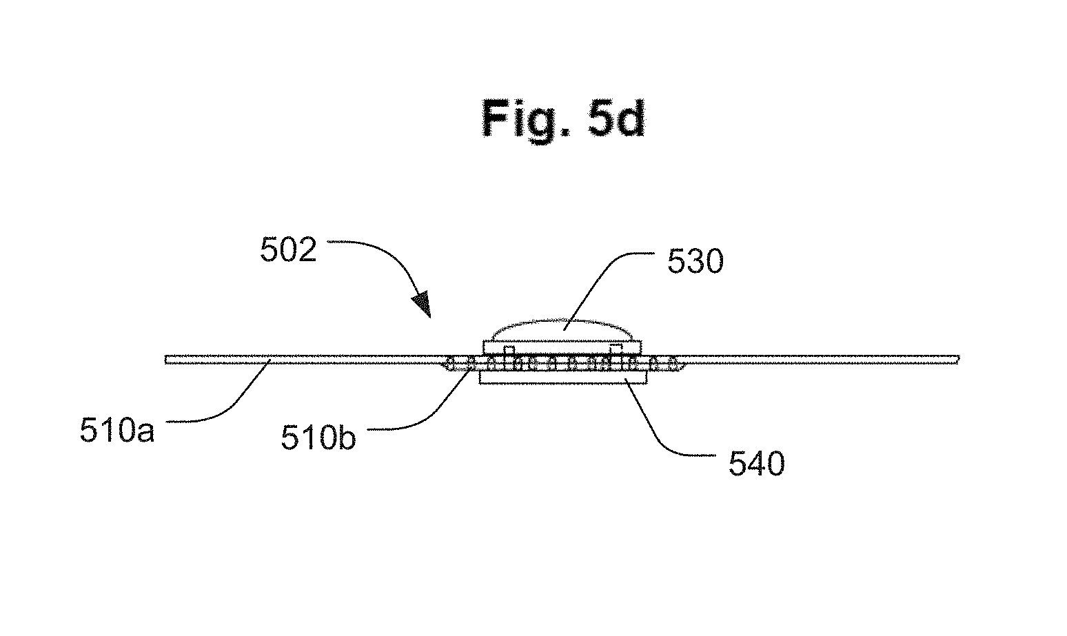
[0023] FIG. 5d illustrates a side view of another wearable electronic device in accordance with an example embodiment;
[0024] FIG. 6a illustrates a side view of a wearable electronic device configured to have a heat spreading cloth engage top and bottom surfaces of an electronic component in accordance with an example embodiment;
[0025] FIG. 6b illustrates the wearable electronic device of FIG. 6a with the heat spreading cloth engaging the electronic component and fused together in accordance with an example embodiment;
[0026] FIG. 7 illustrates a garment having a wearable electronic device coupled thereto in accordance with an example embodiment;
[0027] FIG. 8 illustrates a garment having a wearable electronic device coupled thereto in accordance with another example embodiment;
[0028] FIG. 9 illustrates a computing system in accordance with an example embodiment;
[0029] FIG. 10a illustrates an example of a weaving pattern;
[0030] FIG. 10b illustrates an example of another weaving pattern;
[0031] FIG. 10c illustrates an example of yet another weaving pattern; and
[0032] FIG. 10d illustrates an example of an additional weaving pattern.
DESCRIPTION OF EMBODIMENTS
[0033] Although the following detailed description contains many specifics for the purpose of illustration, a person of ordinary skill in the art will appreciate that many variations and alterations to the following details can be made and are considered to be included herein. Accordingly, the following embodiments are set forth without any loss of generality to, and without imposing limitations upon, any claims set forth. It is also to be understood that the terminology used herein is for the purpose of describing particular embodiments only, and is not intended to be limiting. Unless defined otherwise, all technical and scientific terms used herein have the same meaning as commonly understood by one of ordinary skill in the art to which this disclosure belongs.
[0034] As used in this written description, the singular forms "a," "an" and "the" include express support for plural referents unless the context clearly dictates otherwise. Thus, for example, reference to "a sensor" includes support for a plurality of such sensors.
[0035] As used herein, "comprises," "comprising," "containing" and "having" and the like can have the meaning ascribed to them in U.S. Patent law and can mean "includes," "including," and the like, and are generally interpreted to be open ended terms. The terms "consisting of" or "consists of" are closed terms, and include only the components, structures, steps, or the like specifically listed in conjunction with such terms, as well as that which is in accordance with U.S. Patent law. "Consisting essentially of" or "consists essentially of" have the meaning generally ascribed to them by U.S. Patent law. In particular, such terms are generally closed terms, with the exception of allowing inclusion of additional items, materials, components, steps, or elements, that do not materially affect the basic and novel characteristics or function of the item(s) used in connection therewith. For example, trace elements present in a composition, but not affecting the compositions nature or characteristics would be permissible if present under the "consisting essentially of" language, even though not expressly recited in a list of items following such terminology. When using an open ended term, like "comprising" or "including," in this written description it is understood that direct support should be afforded also to "consisting essentially of" language as well as "consisting of" language as if stated explicitly and vice versa.
[0036] The terms "first," "second," "third," "fourth," and the like in the description and in the claims, if any, are used for distinguishing between similar elements and not necessarily for describing a particular sequential or chronological order. It is to be understood that any terms so used are interchangeable under appropriate circumstances such that the embodiments described herein are, for example, capable of operation in sequences other than those illustrated or otherwise described herein. Similarly, if a method is described herein as comprising a series of steps, the order of such steps as presented herein is not necessarily the only order in which such steps may be performed, and certain of the stated steps may possibly be omitted and/or certain other steps not described herein may possibly be added to the method.
[0037] The terms "left," "right," "front," "back," "top," "bottom," "over," "under," and the like in the description and in the claims, if any, are used for descriptive purposes and not necessarily for describing permanent relative positions. It is to be understood that the terms so used are interchangeable under appropriate circumstances such that the embodiments described herein are, for example, capable of operation in other orientations than those illustrated or otherwise described herein. The term "coupled," as used herein, is defined as directly or indirectly connected in an electrical or nonelectrical manner. Objects described herein as being "adjacent to" each other may be in physical contact with each other, in close proximity to each other, or in the same general region or area as each other, as appropriate for the context in which the phrase is used. Occurrences of the phrase "in one embodiment," or "in one aspect," herein do not necessarily all refer to the same embodiment or aspect.
[0038] As used herein, comparative terms such as "increased," "decreased," "better," "worse," "higher," "lower," "enhanced," "maximized," "minimized," and the like refer to a property of a device, component, or activity that is measurably different from other devices, components, or activities in a surrounding or adjacent area, in a single device or in multiple comparable devices, in a group or class, in multiple groups or classes, or as compared to the known state of the art, or to a comparable device lacking identical features or components. For example, a data region that has an "increased" risk of corruption can refer to a region of a memory device, which is more likely to have write errors to it than other regions in the same memory device. A number of factors can cause such increased risk, including location, fabrication process, number of program pulses applied to the region, etc.
[0039] The terms "coupled" and "attached" can be used interchangeably herein, and are defined as directly or indirectly connected in an electrical or nonelectrical manner. Objects or components that are attached or coupled can be merely held in a fixed relationship without necessarily being physically joined. For example, woven fibers may be attached to one another by intertwining through a weaving process. "Directly coupled" or "directly attached" objects, structures, or elements are in physical contact with one to another and in some embodiments may be "merged" or "fused" for example by sintering. Objects described herein as being "adjacent to" each other may be in physical contact with each other, in close proximity to each other, or in the same general region or area as each other, as appropriate for the context in which the phrase is used.
[0040] As used herein, the term "substantially" refers to the complete or nearly complete extent or degree of an action, characteristic, property, state, structure, item, or result. For example, an object that is "substantially" enclosed would mean that the object is either completely enclosed or nearly completely enclosed. The exact allowable degree of deviation from absolute completeness may in some cases depend on the specific context. However, generally speaking the nearness of completion will be so as to have the same overall result as if absolute and total completion were obtained. The use of "substantially" is equally applicable when used in a negative connotation to refer to the complete or near complete lack of an action, characteristic, property, state, structure, item, or result. For example, a composition that is "substantially free of" particles would either completely lack particles, or so nearly completely lack particles that the effect would be the same as if it completely lacked particles. In other words, a composition that is "substantially free of" an ingredient or element may still actually contain such item as long as there is no measurable effect thereof.
[0041] As used herein, the term "about" is used to provide flexibility to a numerical range endpoint by providing that a given value may be "a little above" or "a little below" the endpoint. Unless otherwise stated, use of the term "about" in accordance with a specific number or numerical range should also be understood to provide support for such numerical terms or range without the term "about". For example, for the sake of convenience and brevity, a numerical range of "about 50 angstroms to about 80 angstroms" should also be understood to provide support for the range of "50 angstroms to 80 angstroms." Furthermore, it is to be understood that in this specification support for actual numerical values is provided even when the term "about" is used therewith. For example, the recitation of "about" 30 should be construed as not only providing support for values a little above and a little below 30, but also for the actual numerical value of 30 as well.
[0042] As used herein, a plurality of items, structural elements, compositional elements, and/or materials may be presented in a common list for convenience. However, these lists should be construed as though each member of the list is individually identified as a separate and unique member. Thus, no individual member of such list should be construed as a de facto equivalent of any other member of the same list solely based on their presentation in a common group without indications to the contrary. In addition, various embodiments and examples can be referred to herein along with alternatives for the various components thereof. It is understood that such embodiments, examples, and alternatives are not to be construed as de facto equivalents of one another, but are to be considered as separate and autonomous representations under the present disclosure.
[0043] Furthermore, the described features, structures, or characteristics can be combined in any suitable manner in one or more embodiments. In the following description, numerous specific details are provided, such as examples of layouts, distances, network examples, etc., to provide a thorough understanding of embodiments. One skilled in the relevant art will recognize, however, that the technology can be practiced without one or more of the specific details, or with other methods, components, layouts, etc. In other instances, well-known structures, materials, or operations may not be shown or described in detail to avoid obscuring aspects of the disclosure.
[0044] Concentrations, amounts, and other numerical data may be expressed or presented herein in a range format. It is to be understood that such a range format is used merely for convenience and brevity and thus should be interpreted flexibly to include not only the numerical values explicitly recited as the limits of the range, but also to include all the individual numerical values or sub-ranges encompassed within that range as if each numerical value and sub-range is explicitly recited. As an illustration, a numerical range of "about 1 to about 5" should be interpreted to include not only the explicitly recited values of about 1 to about 5, but also include individual values and sub-ranges within the indicated range. Thus, included in this numerical range are individual values such as 2, 3, and 4 and sub-ranges such as from 1-3, from 2-4, and from 3-5, etc., as well as 1, 2, 3, 4, and 5, individually.
[0045] This same principle applies to ranges reciting only one numerical value as a minimum or a maximum. Furthermore, such an interpretation should apply regardless of the breadth of the range or the characteristics being described.
[0046] Reference throughout this specification to "an example" means that a particular feature, structure, or characteristic described in connection with the example is included in at least one embodiment. Thus, appearances of the phrases "in an example" in various places throughout this specification are not necessarily all referring to the same embodiment.
Example Embodiments
[0047] An initial overview of invention embodiments is provided below and specific embodiments are then described in further detail. This initial summary is intended to aid readers in understanding the technological concepts more quickly, but is not intended to identify key or essential features thereof, nor is it intended to limit the scope of the claimed subject matter.
[0048] One of the challenges associated with wearable or flexible devices is that there are few thermal solutions available for such devices. For example, in some cases, it can be beneficial for a wearable device to be very thin, light, and/or include multifunctional parts. However, many existing thermal solutions are relatively heavy, rigid, and inflexible (e.g. heat sinks, vapor chambers, graphite spreaders, etc.). Thus, some current solutions include power management, limiting range of motion, or dealing with large thermal solutions.
[0049] The present disclosure describes examples of heat spreading cloths and associated devices, systems, and methods to help provide a thermal solution for wearable electronics devices that can be thin, light, and flexible. For example, heat spreading cloths can include a plurality of attached polymeric fibers that are thermally conductive and electrically insulative. Additionally, heat spreading cloths can include an electronics area configured to thermally couple to an electronic device in a heat spreading relationship. Heat spreading cloths can also be incorporated into wearable electronic devices. For example, wearable electronic devices can include an electronic component and a heat spreading cloth thermally coupled to the electronic component. The heat spreading cloth can include a plurality of attached thermally conductive and electrically insulative polymeric fibers. Further still, wearable electronic devices can be incorporated into various systems. Some example systems can include a wearable electronic device as described herein and a remote computing device configured to wirelessly communicate with the wearable electronic device.
[0050] In the present disclosure, it is noted that when discussing the heat spreading cloths, the wearable electronic devices, the systems, and the various methods, each of these discussions can be considered applicable to each of these examples, whether or not they are explicitly discussed in the context of that example. Thus, for example, in discussing details about heat spreading cloths per se, such discussion also refers to the wearable electronic devices, the systems, and the various methods described herein, and vice versa.
[0051] FIG. 1a illustrates an example of a heat spreading cloth 100a. The heat spreading cloth can include a plurality of attached thermally conductive and electrically insulative polymeric fibers 110 oriented in a radial weave. In this particular example, an electronics area 120 of the heat spreading cloth 110a can include an area having a high density or concentration of polymeric fibers 110 (e.g. higher than in other areas of the cloth, for example by increased thickness, density, weave tightness, etc.). FIG. 1b illustrates another example of a heat spreading cloth 100b. FIG. 1b can illustrate different embodiments of a heat spreading cloth. For example, in some cases, heat spreading cloth 100b can include a plurality of attached or coupled thermally conductive and electrically insulative polymeric fibers 110a and 110b that are interwoven together in a plain weave. The densely woven area 120 can include an electronics area. However, in some other examples, heat spreading cloth 100b can include a plurality of attached thermally conductive and electrically insulative polymeric fibers 110a and plurality of non-thermally conductive carrier fibers 110b that are co-woven together. In this example, the electronics area can include an area 120 of the co-weave or another suitable area of attachment to the polymeric fibers 110a. In some examples, individual polymeric fiber ends can be stitched or otherwise integrated into a larger carrier fabric or garment for use as a heat spreading component of an electronic device.
[0052] In further detail, a variety of thermally conductive polymeric fibers can be used to prepare a heat spreading cloth. Typically, any suitable polymeric fiber can be used that is both thermally conductive and electrically insulative. In further detail, the polymeric fibers can typically have a thermal conductivity of greater than or equal to 5 watts per meter kelvin (W/m-K). In other examples, the polymeric fibers can have a thermal conductivity of greater than or equal to 10 W/m-k. In some other examples, the polymeric fibers can have a thermal conductivity of greater than or equal to 20 W/m-k. In yet other examples, the polymeric fibers can have a thermal conductivity of greater than or equal to 30 W/m-k, 40 W/m-K, or 50 W/m-K. In some further examples, the polymeric fibers can have a thermal conductivity of greater than or equal to 100 W/m-K.
[0053] One way of obtaining a polymeric fiber with high thermal conductivity is to stretch or otherwise chemically or mechanically process the polymeric fibers to achieve individual polymer chains with a high degree of molecular alignment. As will be appreciated by one skilled in the art, bulk polymer materials are typically randomly entangled without a high degree of molecular alignment and are generally regarded as thermal insulators. However, individual polymer chains within the bulk material can have high thermal conductivities. Without wishing to be bound by theory, it is believed that the random arrangement of thermally conductive individual polymer chains can render the overall bulk material thermally insulating. However, a polymeric fiber with high thermal conductivity can be obtained by mechanically, chemically, or otherwise processing the polymeric fibers (e.g. by repeatedly stretching the bulk polymer material) until a high degree of molecular alignment is achieved for individual polymer chains within the fiber. In some examples, the high degree of molecular alignment can increase phonon transport along the polymeric fibers. One way of measuring the degree of molecular alignment is by measuring the thermal conductivity of the fiber. For example, in some cases, an unstretched fiber can be thermally insulating (e.g. having a thermal conductivity of about 0.1 W/m-K to about 0.5 W/m-K). After repeatedly stretching the polymeric fiber, the thermal conductivity of the polymeric fiber can increase to provide a non-isotropic thermally conductive polymeric fiber (e.g with a thermal conductivity in a longitudinal direction of at least 5 W/m-K). Of course, the thermal conductivities of the polymer fibers can vary depending on the particular polymeric material employed and the degree of polymer alignment.
[0054] The polymeric fibers can also be electrically insulating. For example, in some general aspects, the polymer fibers can have a dielectric strength of from about 100 to about 300 kV/cm (kilovolt per centimeter). In some further examples, the volumetric resistivity (e.g. the resistance to flow of electrical current through the three-dimensional volume) of the polymeric fibers can be from about 1.times.10.sup.12 to about 1.times.10.sup.16 ohms/centimeter. Additionally, in some cases, the surface resistivity (e.g. the resistance to flow of electrical current across the surface) of the polymeric fibers can be from about 1.times.10.sup.10 ohms/square to about 1.times.10.sup.15 ohms/square. Of course, the electrically insulating properties of the polymer fibers can vary depending on the particular polymeric material employed.
[0055] In some specific examples, the polymeric fibers can include or be made of a thermoplastic material. Non-limiting examples of thermoplastic materials can include acrylics (e.g. poly(methyl methacrylate)), acrylate styrene acrylonitrile, acrylonitrile butadiene styrene, ethylene vinyl acetate, polyamides (e.g. nylon), polylactic acid, polybenzimidazole, polycarbonate, polyether sulfone, polyoxymethylene, polyether ketone, polyetherimide, polyethylene, polyphenylene oxide, polyphenylene sulfide, polypropylene, polystyrene, polyurethane, polyvinyl chloride, polyvinylidene fluoride, polytetrafluoroethylene, styrene acrylonitrile, the like, or a combination thereof. In some specific examples, the thermoplastic material can include ethylene vinyl acetate, polyamide, polybenzimidazole, polycarbonate, polyethylene, polypropylene, polyurethane, polyvinyl chloride, the like, or combinations thereof
[0056] In some examples, the use of a thermoplastic material can facilitate attachment of individual polymeric fibers to one another, to a carrier fiber or fabric, to an electronic component, or a combination thereof. For example, where the polymeric fibers include or are made of a thermoplastic material, the fibers can be heated to a sufficient temperature to fuse the polymeric fibers to one another, to a carrier fiber or fabric, to an electronic component, or a combination thereof. One example is illustrated in FIGS. 1c and 1d. FIG. 1c illustrates a plurality of aligned polymeric fibers 110 of a heat spreading cloth 100c prior to fusion. FIG. 1d illustrates the plurality of aligned polymeric fibers 110 of FIG. 1c after heat fusion (e.g. heat fusion, chemical fusion, etc.). It is noted that FIGS. 1c and 1d illustrate a simplified version of this process and are intended to be illustrative rather than limiting. As will be appreciated by one skilled in the art, a fusion process, such as a heat fusion process, can be similarly performed with any suitable interweaving pattern, co-weaving pattern, etc., of polymeric fibers or types of polymeric fibers and optionally one or more carrier fibers or types of carrier fibers.
[0057] Whether or not heat fusion is employed, individual polymeric fibers can be attached in a number of ways. In some examples, the polymeric fibers can be attached to one another by interweaving individual polymeric fibers. In some further examples, the interwoven polymeric fibers can be further heated to fuse the polymeric fibers together, to a carrier fiber or fabric, to an electronic component, or a combination thereof. In some additional examples, the polymeric fibers can be attached by co-weaving the polymeric fibers with a carrier fiber. In some further examples, the co-woven polymeric fibers can be further heated to fuse the polymeric fibers together, to a carrier fiber or fabric, to an electronic component, or a combination thereof. In some examples, the polymeric fibers can be aed by stitching individual polymeric fibers into a carrier fabric. In some further examples, the stitched polymeric fibers can be further heated to fuse the polymeric fibers together, to a carrier fiber or fabric, to an electronic component, or a combination thereof.
[0058] As described above in some examples, a carrier fiber or carrier fabric can be used in the heat spreading cloths. Carrier fibers can be valuable in imparting a particular feel, appearance, quality, integrity, etc. for the heat spreading cloth. In some examples, the carrier fiber or carrier fabric can include or be made of a natural fiber. Non-limiting examples of natural fibers can include cotton, linen (flax), ramie, silk, wool, cashmere, hemp, jute, the like, or a combination thereof. In some examples, the carrier fiber or carrier fabric can include or be made of a synthetic fiber. Non-limiting examples of synthetic fibers can include rayon, polyesters, acrylics, polyethylene, polyvinyl chloride, polychloroprene, aramids, polyamides, elastane, the like, or a combination thereof.
[0059] Thus, in some examples, the heat spreading cloths can be formed entirely of thermally conductive polymeric fibers. In other examples, the heat spreading cloths can be formed of or otherwise comprise thermally conductive polymeric fibers and carrier fibers. Where this is the case, the polymeric fibers can typically include or form at least 20 weight percent (wt %) of the heat spreading cloth. In other examples, the polymeric fibers can include or form at least 30 wt % of the heat spreading cloth. In still other examples, the polymeric fibers can include or form at least 40 wt % of the heat spreading cloth. In yet other examples, the polymeric fibers can include or form at least 50 wt % of the heat spreading cloth. In some additional examples, the polymeric fibers can include or form at least 60 wt %, 70 wt %, or 80 wt % of the heat spreading cloth. In some examples, the heat spreading cloth can include or be formed entirely of polymeric fibers.
[0060] It is noted that the polymeric fibers can have a variety of linear mass densities. Typically, the polymeric fibers can have a linear mass density of from about 10 denier to about 6000 denier. In some examples, the polymeric fibers can have a linear mass density of from about 60 denier to about 1600 denier. In some additional examples, the polymeric fibers can have a linear mass density of from about 30 denier to about 500 denier.
[0061] As described above, the heat spreading cloth can include an electronics area configured to thermally couple to an electronic device in a heat spreading relationship. FIGS. 2a-2e illustrate various examples of heat spreading cloths having an electronics area (e.g. an identified, pre-identified, designated, or pre-designated area to which an electronics device or component is to be coupled or attached). As will all figures contained herein, it is noted that these examples are not necessarily drawn to scale and are illustrated only generically for the sake of discussion. For example, it is noted individual thermally conductive polymeric fibers are not illustrated for heat spreading cloths 200a-200e. Nonetheless, heat spreading cloths 200a-200e can be prepared in a number of ways, such as those described elsewhere herein. As non-limiting examples, heat spreading cloths 200a-200e can be prepared by interweaving or fusing thermally conductive polymeric fibers (e.g. as shown in FIGS. 1a-1d), co-weaving thermally conductive polymeric fibers with carrier fibers (e.g. alternative embodiments in FIGS. 1a and 1b), stitching polymeric fibers into a carrier fabric, applying a patch of polymeric fibers to a carrier fabric, or the like. With this in mind, FIG. 2a illustrates an electronics area 220 positioned centrally on heat spreading cloth 200a. While in some examples it can be advantageous to position the electronics area centrally on the heat spreading cloth, in other examples it may not be. Thus, in some cases, as illustrated in FIG. 2b, an electronics area 220 can be positioned toward a perimeter of a heat spreading cloth 200b. In some cases, the size and location of the electronics area can also depend on the size and/or number of electronics devices to be attached to the heat spreading cloth. Thus, as illustrated in FIG. 2c, a heat spreading cloth 200c can include an electronics area 220 that can extend from one perimeter edge of the heat spreading cloth 200c to an opposing perimeter edge of the heat spreading cloth. In some examples, this can accommodate larger electronic components and/or a plurality of electronic components within a common electronics area 220. FIG. 2d illustrates a heat spreading cloth 200d having a centrally positioned, but elongated, electronics area 220. This can accommodate a specifically sized or shaped electronic component, for example, and can be sized or shaped in any suitable geometry to accommodate a specific electronic component. FIG. 2e illustrates a heat spreading cloth 200e having a plurality of electronics areas 220a, 220b configured for coupling a plurality of electronics devices thereto.
[0062] In further detail, in some examples, the electronics area can be marked for placement of an electronics device. For example, in some cases, the electronics area can be marked with a label, symbol, or other marking to designate a specific area of the heat spreading cloth as the electronics area. This can be done by printing, dying, stitching, or otherwise marking the area accordingly. No specific markings or labeling is required so long as it identifies the area of the heat spreading cloth as the electronics area.
[0063] In some other examples, the electronics area can be an area of the heat spreading cloth that includes an effective heat spreading weave or orientation of the polymeric fibers, with or without additional markings to designate the area as the electronics area.
[0064] An effective heat spreading weave can depend on a number of factors, such as the type of fiber employed, fiber thickness, the amount of fiber employed, the linear mass density of the fiber, the heating power of the electronic device, etc. Thus, there can be a number of effective heat spreading weaves. Non-limiting examples of weaves that can be effective heat spreading weaves can include a plain weave, a basket weave, a twill weave, a jacquard weave, a satin weave, a dobby weave, a radial weave, a leno weave, double cloth weave, the like, or a combination thereof.
[0065] In some examples, the electronics area can include an effective heat spreading orientation of the polymeric fibers. For example, the polymeric fibers need not be interwoven or co-woven with a carrier fiber to be effective heat spreaders. In some examples, the effective heat spreading orientation can include a stitching pattern of the polymeric fibers incorporated into a carrier fabric. In other examples, the effective heat spreading orientation can include a patch including or formed of the polymeric fibers that is adhered to, fused to, stitched to, or otherwise coupled to a carrier fabric.
[0066] In some examples, the electronics area can be an area of the heat spreading cloth that is substantially free of a carrier fiber. In some specific examples, the electronics area can include from about 0 wt % to about 50 wt % of a carrier fiber. In other examples, the electronics area can include from about 0 wt % to about 10 wt % of a carrier fiber. In still other examples, the electronics area can include from about 5 wt % to about 25 wt % of a carrier fiber. In yet other examples, the electronics area can include from about 15 wt % to about 40 wt % of a carrier fiber. In some examples, the electronics area can include at least 20 wt %, 30 wt %, 40 wt %, 50 wt % or 60 wt % of the polymeric fibers.
[0067] In some examples, the electronics area can be an area of the heat spreading cloth including a polymeric material suitable for attachment of the electronic device thereto via fusing, melting, sintering, or the like. For example, in some cases, the electronics area can include a sufficient amount of polymeric fibers made of a thermoplastic material that an electronic device can be attached to the heat spreading cloth at the electronics area via fusing, melting, sintering, or the like.
[0068] While not required, in some additional examples, the electronics area can be an area that is thicker than the rest of the heat spreading cloth. For example, in some cases, the electronics area can be at least 10% thicker than other areas of the heat spreading cloth. In other examples, the electronics area can be at least 25% thicker than other areas of the heat spreading cloth. In still other examples, the electronics area can be at least 50% thicker than other areas of the heat spreading cloth. In yet other examples, the electronics area can be at least twice as thick as other areas of the heat spreading cloth. In some cases, a thickened electronics area can facilitate enhanced local heat spreading. In some additional examples, a thickened electronics area can facilitate thermal attachment of an electronic component thereto. In yet other examples, a thickened electronics area can provide additional structural support for the electronic component. In some specific examples, the electronics area can be a location of interface for a power source sensor, accessory, plug, the like, or a combination thereof.
[0069] In some additional examples, the electronics area can be an area of the heat spreading cloth that includes a base for mounting or mechanically securing an electronic device thereto. The base can be configured to secure the electronic device thereto via clamps, clips, screws, pins, threaded attachment, magnetic attachment, friction fitting, straps, cam-lock attachment, adhesive, the like, a combination thereof, or using other attachment mechanisms. In some examples, the base can include an intermediary heat transfer substrate thermally coupled to the polymeric fibers (e.g. as via fusing, melting, or sintering, a portion of the polymeric fibers to attach the base thereto, for example). The intermediary heat transfer substrate can be positioned to interface with a heat-generating component of the electronic device. The intermediary heat transfer substrate can be made of or include any suitable heat transfer material, such as copper, aluminum, graphite, diamond, the like, or a combination thereof.
[0070] As described above, the electronics area can be located at a variety of positions of the heat spreading cloth. For example, in some cases, the electronics area can be disposed at a perimeter of the heat spreading cloth. In some examples, the electronics area can be disposed at a central location of the heat spreading cloth. In some examples, the heat spreading cloth can include a plurality of electronics areas. Where this is the case, the plurality of electronics areas can be positioned at a variety of locations on the heat spreading cloth. For example, in some cases at least one electronics area can be positioned at a central location of the heat spreading cloth. In some examples, at least one of the electronics areas can be positioned at a perimeter of the heat spreading cloth. In some examples, at least one of the electronics areas can be positioned at a central location of the heat spreading cloth and at least one electronics area can be positioned at a perimeter of the heat spreading cloth. In some examples, each of the electronics areas can be positioned at a central location of the heat spreading cloth. In yet other examples, each of the electronics areas can be positioned at or along a perimeter of the heat spreading cloth.
[0071] The heat spreading cloth can also be associated with a garment, for example, to form a wearable article. For example, in some cases, the heat spreading cloth can be attached or otherwise integrated into a garment, such as via sewing, adhering, fusing, magnetically coupling, clipping, clamping, snapping, strapping, tying, securing via hook and loop fasteners, the like, or a combination thereof. In some examples, the heat spreading cloth can be integrated into a garment to form a part of the garment. In either case, a variety of garments or other articles can be used for attachment of the heat spreading cloth. Non-limiting examples can include a shirt, pants, shorts, footwear, a jacket, a scarf, a watch, jewelry (e.g. necklace, bracelet, earrings, etc.), a headband, eyewear, earwear, a glove, a sock, a hat, an undergarment, athletic equipment (e.g. athletic apparel, helmet, mask, protective padding, etc.), strap (e.g. chest strap, arm strap, leg strap, etc.) the like, or a combination thereof.
[0072] The present disclosure is also directed to wearable electronic devices. In some examples, a wearable electronic device can include an electronic component and a heat spreading cloth thermally coupled to the electronic component. The heat spreading cloth can include a plurality of attached thermally conductive and electrically insulative polymeric fibers, such as those described elsewhere herein. Generally, the heat spreading cloth of the wearable electronic device can include one or more of the features described elsewhere herein regarding heat spreading cloths.
[0073] As one non-limiting example, FIGS. 3a and 3b illustrate an example of an electronic component 330 that can be coupled to a heat spreading cloth in a heat spreading relationship. For example, as illustrated in FIGS. 3c and 3d, electronic component 330 can be coupled to a plurality of thermally conductive and electrically insulative polymeric fibers 310 in a heat spreading relationship to form a wearable electronic device 302. Similarly, FIGS. 4a and 4b illustrate another example of an electronic component 430 that can be coupled to a heat spreading cloth in a heat spreading relationship. For example, as illustrated in FIGS. 4c and 4d, electronic component 430 can be coupled to a plurality of thermally conductive and electrically insulative polymeric fibers 410a (and optionally 410b) in a heat spreading relationship to form a wearable electronic device 402. As described above, fibers 410b can represent thermally conductive polymeric fibers interwoven with polymeric fibers 410a, or a non-thermally conductive carrier fiber co-woven with polymeric fibers 410a, depending on the particular desired application.
[0074] A variety of electronic components or devices can be included as part of the wearable electronic device, such as computing devices, memory and storage devices, media devices, data logging and collection devices, control actuators, security tokens/devices, atmospheric, biologic, or pressure sensors or monitors, and the like. More specific electronic devices or components can include an activity tracker, a heart rate monitor, a blood pressure monitor, an oxygen monitor, a perspiration/hydration monitor, a sleep monitor, a temperature monitor, a global positioning system (GPS), a gyroscope, or combinations thereof.
[0075] The electronic component or device can also include a number of accessories such as a speaker, a microphone, a display, an alarm indicator (e.g. audible alarm, visible alarm, vibrational alarm, thermal alarm, or a combination thereof), a light (e.g. a flashlight), a display screen or other visual output or indicator, electronic paper (e-paper), an electro-wetting display, adaptive colors, ink (e.g. electronic ink or "e-ink") or combinations thereof.
[0076] The electronic component or device can include a variety of other parts or components, such as a power module, a data collection module, a communication module, a controller module, the like, or a combination thereof. A power module can be configured to power the electronic component. Any power source sufficient to adequately power the electronic component can be used. Batteries, capacitors, solar panels (e.g. flexible solar panels) and/or other power sources (e.g. ambient radio energy, solar energy, optical remote charging, vibration energy, kinetic energy, thermal energy, etc.) may be selected in view of the electronic component's intended purpose and duration and nature of operation. In one aspect, the power module can include a battery. In one example the battery can be a rechargeable battery. Other components can be included in the power module, for example, wires and electrical connections required to operably connect the power module to other modules within the electronic component that require power for their operation. In one specific example, the power module may include components that inductively charge the battery when exposed to an adequate external influence, such as a wireless or magnetic influence. In such embodiment, if charging of the battery is necessary or desired, the proper external influence can be brought within a sufficient range to operate the inductive components and charge the battery without physically accessing the electronic component.
[0077] A communication module can be configured to communicate with a remote device, such as a computing device (i.e. computer), mobile device (e.g. smart phone or tablet), or cloud database, in order to transmit and/or receive information. Typical components for such a module may be used. In one aspect, the communication module may include a wireless transmitter/receiver capable of wirelessly communicating with the remote device. Nearly any wireless frequency, range, protocol or type can be used, for example short-wavelength radio waves in various bands, such as Bluetooth (IEEE 802.15.1), Zigbee (IEEE 802.15.4), other IEEE 802.15 protocols, WiMAX or other IEEE 802.16 protocols, local area wireless technologies, such as WiFi, WiFi-direct, or other IEEE 802.11 protocols, cellular, including GMA and CDNA, radio, electromagnetic, acoustic communication (e.g. via piezoelectric transducer, etc.), the like, or a combination thereof. In one embodiment, the wireless transmitter/receiver can be a low power consumption device, for example, Bluetooth.RTM. low energy (LE).
[0078] A controller module can be configured to control the operation of the electronic component, including all aspects of sensor activity, data collection, communications, etc. The controller module can be operatively coupled to the other device modules as necessary to affect such control. The controller module can include one or more processors and memory and can be equipped with program logic sufficient to control all aspects and function of the device. In one example, the program logic of the controller may include instructions to control the communications module based on sensor activity. For example, the controller module can activate or deactivate the communication module and/or other device components upon receiving an indication of an amount, presence, or absence of a sensed component or activity.
[0079] It is noted that, in some examples, the electronic component can be designed to have a heating power less than or equal to 5 watts (W). In some examples, the heat spreading cloth can be effective at spreading heat for an electronic component having a heating power less than or equal to 5 W. However, in other examples, the heat spreading cloth can be effective at spreading heat for an electronic component having a heating power greater than 5 W. In some examples, the electronic device can have a heating power of from about 1 W to about 5 W. In some other examples, the electronic device can have a heating power of from about 0.5 W to about 3 W.
[0080] In some other examples, the electronic device can be removably coupled to the heat spreading cloth. In some specific examples, this can be accomplished via a base coupled to the heat spreading cloth, such as is described elsewhere herein. This is generally illustrated in FIG. 5a. Specifically, an electronic component 530 can be coupled removably (or in some cases, permanently) coupled to a base 540. The base 540 can be configured to attach to the electronic component 530 in any suitable way, such as via clamps, clips, screws, pins, threaded attachment, magnetic attachment, friction fitting, straps, cam-lock attachment, adhesive, the like, or a combination thereof. In some examples, as illustrated in FIGS. 5b and 5c, the base 540 can be configured to couple to the electronic component 530 on a common side of the plurality of attached polymeric fibers 510a (and optionally 510b, which can alternatively represent carrier fibers) to form a wearable electronic device 502. In some cases, this can require the base 540 to include an intermediary heat transfer surface or medium to transfer heat to the heat spreading polymeric fibers 510a. However, in some other examples, as illustrated in FIG. 5d, the base 540 can be configured to couple to the electronic component 530 through the plurality of attached polymeric fibers 510a to form the wearable device 502. In this example, the polymeric fibers 510a can be positioned in direct contact with the electronic component 530 in a heat spreading relationship. It is noted that while FIG. 5d illustrates pins or screws penetrating the plurality of thermally conductive polymeric fibers 510a to couple to the base 540 to the electronic component 530, this can also be accomplished via magnetic retention or the like without penetrating the plurality of polymeric fibers 510a.
[0081] In some examples, the electronic component can be removably attached to the heat spreading cloth without a base. In some examples, this can be accomplished via an adhesive, magnetic retention, a clamp, a clip, a strap, screws, pins, a hook and loop fastener, the like, or a combination thereof.
[0082] In some examples, the electronic component can be permanently coupled to the heat spreading cloth. In some examples, the electronic component can be permanently thermally coupled to the heat spreading cloth via fusing, melting, sintering, or the like a portion of the polymeric fibers to thermally couple the electronic component thereto. One non-limiting example of permanent attachment is illustrated in FIGS. 6a-6b. These figures illustrate a process of laminating an electronic device 630 between a first heat spreading cloth 600a and a second heat spreading cloth 600b or a first portion 600a of a heat spreading cloth and a second portion 600b of the heat spreading cloth to form a wearable electronic device 602. In this example, the electronic component can be enveloped by the heat spreading cloth such that the electronic component is contacted on all sides by the heat spreading cloth. In some examples, the heat spreading cloth can be fused to the electronic component. In one example, the heat spreading cloth may be or comprise an outer housing or case for the electronic device or component. In this as well as in other embodiments, the heat spreading cloth may be directly coupled to at least one heat-generating part, area, or component of the electronics device. Such direct contact can maximize transfer and movement of heat energy away from the electronics device or component. In some embodiments, the contact interface between the heat spreading cloth and the electronics device or component (or portion thereof, whether as a housing or case or not) can be substantially free of voids, spaces (e.g. air spaces), or gaps and can be substantially continuous.
[0083] The wearable electronic device can also be associated with a garment. For example, in some cases, the wearable electronic device can be attached to a garment, such as via sewing, adhering, fusing, magnetically coupling, clipping, clamping, snapping, strapping, tying, securing via hook and loop fasteners, the like, or a combination thereof. In some examples, the wearable electronic device can be integrated into a garment to form a part of the garment. In either case, a variety of garments can be used for attachment of the wearable electronic device. Non-limiting examples can include a shirt, pants, shorts, footwear, a jacket, a scarf, a watch, jewelry (e.g. necklace, bracelet, earrings, etc.), a headband, eyewear, earwear, a glove, a hat, an undergarment, athletic equipment (e.g. athletic apparel, helmet, mask, protective padding, etc.), the like, or a combination thereof.
[0084] As one non-limiting example, FIG. 7 illustrates a wearable electronic device 702 coupled to a garment 750. The wearable electronic device 702 includes a plurality of thermally conductive and electrically insulative polymeric fibers 710 stitched into the garment 750. An electronic component 730 has been fused to the plurality of polymeric fibers 710 in a heat spreading relationship. As another non-limiting example, FIG. 8 illustrates a wearable electronic device 802 integrated into a garment 850. In this particular example, wearable electronic device 802 includes a heat spreading cloth 800 that has been integrated into garment 850 so as to form part of the garment 850. An electronic component 830 has been fused to the heat spreading cloth in a heat spreading relationship. Alternatively, FIG. 8 can represent an embodiment where heat spreading cloth 800 has been coupled to garment 850 as a patch on a surface of garment 850.
[0085] In some examples, the wearable electronic device can be included as part of a system. The system can include a wearable electronic device as described herein and a remote computing device configured to wirelessly communicate with the wearable electronic device.
[0086] FIG. 9 illustrates a simplified example of a system in accordance with some embodiments of the present disclosure. System 960 may be used in any of the following exemplary systems: a wireless local area network (WLAN) system, a wireless personal area network (WPAN) system, a cellular network, the like, or a combination thereof.
[0087] System 960 can include a controller 962, an input/output (I/O) device 964 (e.g. a keypad, display, etc.), a memory 966, a wireless interface 968, and any other suitable component coupled to each other via a bus 970. A battery 972 or other power source can be used in some embodiments. It should be noted that such components are merely exemplary and other components not specifically recited could be used in place of or included along with one or more of the above-recited components. In one example, the system 960 may include a processor 974, a power source or battery 972, and a memory 966 coupled to the processor.
[0088] Controller 962 may comprise, for example, one or more microprocessors, digital signal processors, microcontrollers, or the like. Memory 966 may be used to store messages transmitted to or by system 960. Memory 966 may also optionally be used to store instructions that are executed by controller 962 during the operation of system 960, and may be used to store user data. Memory 966 may be provided by one or more different types of memory. For example, memory 966 may comprise any type of random access memory, a volatile memory, a non-volatile memory such as a flash memory, etc.
[0089] I/O device 964 may be used by a user to generate a message. System 960 may use wireless interface 968 to transmit and receive messages to and from remote device 990 or other wireless communication network with a radio frequency (RF) signal, for example. Examples of wireless interface 968 may include an antenna, a wireless transceiver, or other signal transmitting/receiving devices.
[0090] In further detail, the wearable electronic device can be configured to communicate with a variety of remote devices. Remote devices can include a computing device (e.g. a laptop computer, desktop computer, etc.), mobile device (e.g. smart phone, tablet, other smart mobile device, etc.), server, cloud database, gateway, smart hub the like, or a combination thereof. Further, the remote device can be configured to wirelessly communicate with the wearable electronic device via any suitable wireless communication technology. For example, the remote device can be configured to communicate with the wearable electronic device via Bluetooth.RTM. (IEEE 802.15.1), Zigbee.RTM. (IEEE 802.15.4), other IEEE 802.15 protocols, WiMAX or other IEEE 802.16 protocols, local area wireless technologies, such as WiFi, WiFi-direct, or other IEEE 802.11 protocols, cellular, including GMA and CDNA, radio, electromagnetic, the like, or a combination thereof In one embodiment, the wireless transmitter/receiver can be a low power consumption device, for example, Bluetooth.RTM. low energy (LE).
[0091] In some examples, the remote device can be configured to send outgoing information to the wearable electronic device. For example, the remote device can be configured to transmit user-entered or user-prompted information to the wearable electronic device. As a few non-limiting examples, a user of the wearable electronic device can send commands for the wearable electronic device to track certain metrics over period of time (e.g. a used-defined period of time, an automatically recurring period of time, etc.), instructions to control standard settings of the wearable electronic device, instructions regarding data collected by wearable electronic device (e.g. to save data, delete data, transfer data, etc.), instructions to transfer data or information from a remote device to the wearable electronic device, the like, or a combination thereof. In still additional examples, a person (e.g. a parent, guardian, health care provider, personal trainer, coach, etc.) other than the user of the wearable electronic device can send instructions to the wearable electronic device to track certain metrics over period of time (e.g. a used-defined period of time, an automatically recurring period of time, etc.), instructions to control standard settings of the wearable electronic device, instructions regarding data collected by wearable electronic device (e.g. to save data, delete data, transfer data, etc.), instructions to transfer data or information from a remote device to the wearable electronic device, the like, or a combination thereof.
[0092] Additionally, in some examples, the remote device can be configured to receive incoming information from the wearable electronic device. As non-limiting examples, incoming information can include data (e.g. health data, activity data, location data, etc.) collected by a sensor of the wearable electronics device, or user-entered, user-prompted, or user-authorized information (e.g. a start time, a goal, occurrence or absence of a health event, compliance with a health activity, achievement of a milestone, payment authorization, a distress signal, a customized communication, etc.), or the like, or a combination thereof. In some further examples, incoming information can be transmitted from the remote device to a user of the wearable electronic device. For example, in some cases, data collected by the wearable electronic device can be sent to a remote device for processing and subsequently sent back to the wearable electronic device or second remote device of the user. In some examples, the outgoing processed data can trigger an alarm, an alert, a notification, or the like on the wearable electronic device or second remote device of the user. In other examples, the information can be transferred from the remote device to an individual or entity (e.g. a parent, guardian, health care provider, personal trainer, coach, etc.) other than a user of the electronic device, such as to a second remote device or other computing device of the individual or entity, for example. Thus, the remote device can be configured to communicate with the wearable electronic device in a number of ways, such as those described herein and other similar configurations.
[0093] The present disclosure also describes a number of methods, such as methods of manufacturing a heat spreading cloth, methods of manufacturing a wearable electronics device, and methods of cooling an electronics device. In further detail, a method of manufacturing a heat spreading cloth can include attaching a plurality of polymeric fibers that are thermally conductive and electrically insulative. The methods can also include forming an electronics area of the heat spreading cloth. The electronics area can be configured to thermally couple to an electronic device in a heat spreading relationship.
[0094] Various methods of attaching the polymeric fibers are contemplated. As one specific example, the polymeric fibers can be attached by interweaving individual polymeric fibers together. This can be accomplished using any suitable weaving pattern or orientation. In some examples, the polymeric fibers can be attached by co-weaving individual polymeric fibers with a carrier fiber, as described elsewhere herein. Where this is the case, individual polymeric fibers may not come into direct contact with one another. However, in some cases, individual polymeric fibers can come into direct contact with one another when co-woven with a carrier fiber. Where attaching includes weaving, any suitable weaving pattern can be used. Non-limiting examples of weaves that can be effective heat spreading weaves can include a plain weave, a basket weave, a twill weave, a jacquard weave, a satin weave, a dobby weave, a radial weave, a leno weave, double cloth weave, the like, or a combination thereof. Some non-limiting examples of weaving patterns are illustrated in FIGS. 10a-10d.
[0095] In some additional examples, individual polymeric fibers can be attached by stitching the polymeric fibers into a carrier fabric in any suitable stitching pattern or orientation. Where this is the case, individual polymeric fibers may not come into direct contact with one another. However, in some cases, individual polymeric fibers can come into direct contact with one another when stitched into a carrier fabric. In some further examples, individual polymeric fibers can be attached by melting, fusing, sintering, or the like the polymeric fibers together, or to a carrier fiber or fabric, or a combination thereof. Other similar methods of attaching the polymeric fibers can also be used. It is also noted that any suitable combination of methods of attaching the polymeric fibers can also be used.
[0096] Forming an electronics area of the heat spreading cloth can be accomplished in a number of ways. For example, in some cases, the electronics area can be formed by preparing an effective heat spreading weave or orientation of the polymeric fibers, as described elsewhere herein. For example, the effective heat spreading weave or orientation can provide adequate heat spreading for an electronic device when coupled to the electronics area in a heat spreading relationship. In some examples, the electronics area can be marked, such as with an ink, dye, or the like to identify the electronics area.
[0097] Methods of manufacturing a wearable electronic device can include attaching a plurality of polymeric fibers that are thermally conductive and electrically insulative to form a heat spreading cloth. An electronic component can be thermally coupled to the heat spreading cloth in a heat spreading relationship.
[0098] Heat spreading cloths can be prepared as described elsewhere herein. An electronic component can be thermally coupled to the heat spreading cloth in a number of ways, including those described elsewhere herein. It is noted that it can be desirable for the area of contact or the area of interface between the electronic component and the heat spreading cloth to be as large as reasonably possible to minimize thermal resistance. This can be balanced with other design considerations of a particular electronic device and heat spreading cloth. As described, there are numerous ways of coupling an electronic component to a heat spreading cloth. Generally, it is desirable to employ a method of coupling the electronic component to the heat spreading cloth that minimizes or eliminates air pockets or gaps between the electronic component (or a heat producing surface thereof) and the heat spreading cloth. In some examples, an intermediary heat spreader can be employed between the electronic component and the heat spreading cloth. In some examples, an intermediary heat spreader is not employed between the electronic component and the heat spreading cloth. In some specific examples, the electronic component can be coupled to the heat spreading cloth via sintering, fusing, melting, the like, or a combination thereof In some examples, an adhesive, such as a flexible adhesive, can be employed to attach the electronic component to the heat spreading cloth. In some further examples, the adhesive can be doped to enhance a thermal conductivity of the adhesive. In some additional examples, the electronic component can be mechanically coupled to the heat spreading cloth. It is noted that any suitable combination of the methods of coupling described herein, or in combination with other suitable coupling methods, can likewise be employed. It is further noted that these methods of coupling can be employed to facilitate either permanent or temporary/removable attachment of the electronic component to the heat spreading cloth.
[0099] For example, thermally coupling the electronic component to the heat spreading cloth can include permanently coupling the electronic device to the heat spreading cloth. For example, in some cases, the electronic component can be permanently coupled to the heat spreading cloth by melting, fusing, sintering, or the like a portion of the polymeric fibers of the heat spreading cloth to thermally couple the electronic component thereto.
[0100] In some examples, thermally coupling the electronic component to the heat spreading cloth can include removably coupling the electronic component to the heat spreading cloth. In some examples, this can be accomplished via a base or mount configured to mechanically couple the electronic component thereto. The base can be configured to secure the electronic component thereto via clamps, clips, screws, pins, threaded attachment, magnetic attachment, friction fitting, straps, cam-lock attachment, adhesive, the like, or a combination thereof. In some examples, the base can include an intermediary heat transfer substrate thermally coupled to the polymeric fibers (e.g. as via fusing, melting, or sintering, a portion of the polymeric fibers to attach the base thereto, for example). The intermediary heat transfer substrate can be positioned to interface with the electronic component to transfer heat from the electronic component to the heat spreading cloth. The intermediary heat transfer substrate can be made of or include any suitable heat transfer material, such as copper, aluminum, graphite, diamond, the like, or a combination thereof. In some examples, the electronic component can be removably coupled to the heat spreading cloth without a base. For example, in some cases, this can be accomplished via an adhesive, magnetic retention, a clamp, a clip, a strap, screws, pins, a hook and loop fastener, the like, or a combination thereof.
[0101] Methods of cooling an electronic device can include attaching a plurality of thermally conductive and electrically insulating polymeric fibers to form a heat spreading cloth. Additionally, an electronic device can be thermally coupled to the heat spreading cloth in a heat spreading relationship configured to cool the electronic device when in use.
[0102] Methods of attaching polymeric fibers to form a heat spreading cloth are described elsewhere herein. Methods of thermally coupling an electronic device to a heat spreading cloth in a heat spreading relationship are also described elsewhere herein.
[0103] As described above, the heat spreading cloths described herein can be effective heat spreaders for a variety of devices. In some examples, the heat spreading cloths can be effective heat spreaders for devices having a heating power of less than or equal to 5 W (e.g. from about 2 W to about 5 W, or from about 1 W to about 4 W, for example). In other examples, the heat spreading cloths can be effective heat spreaders for devices having a heating power greater than 5 W (e.g. from about 5 W to about 10 W, or greater).
EXAMPLES
[0104] The following examples pertain to specific invention embodiments and point out specific features, elements, or steps that can be used or otherwise combined in achieving such embodiments.
[0105] In one example there is provided, a heat spreading cloth, comprising:
[0106] a plurality of attached polymeric fibers, said polymeric fibers being thermally conductive and electrically insulative; and
[0107] an electronics area configured to thermally couple to an electronic device in a heat spreading relationship.
[0108] In one example of a heat spreading cloth, the plurality of polymeric fibers includes a thermoplastic polymeric fiber.
[0109] In one example of a heat spreading cloth, the thermoplastic polymer fiber includes polyamide, polybenzimidazole, polycarbonate, polyethylene, polypropylene, polyvinyl chloride, or a combination thereof.
[0110] In one example of a heat spreading cloth, the plurality of polymeric fibers includes aligned polymeric fibers having a high degree of molecular alignment to provide the aligned polymeric fibers with a thermal conductivity of at least 10 times the thermal conductivity of the unaligned polymeric fibers.
[0111] In one example of a heat spreading cloth, the polymeric fibers have a linear mass density of from 10 denier to 6000 denier.
[0112] In one example of a heat spreading cloth, the polymeric fibers have a linear mass density of from 60 denier to about 1600 denier.
[0113] In one example of a heat spreading cloth, the polymeric fibers have a linear mass density of from 30 denier to about 500 denier.
[0114] In one example of a heat spreading cloth, the polymeric fibers are attached by interweaving the polymeric fibers.
[0115] In one example of a heat spreading cloth, the cloth further comprises a plurality of carrier fibers.
[0116] In one example of a heat spreading cloth, the carrier fibers are either natural fibers or synthetic fibers.
[0117] In one example of a heat spreading cloth, the carrier fibers include cotton, flax, wool, ramie, silk, polyamide, polyester, elastane, rayon, polyethylene, polyvinyl chloride, polychloroprene, or a combination thereof.
[0118] In one example of a heat spreading cloth, the plurality of polymeric fibers comprises at least 20 wt % of the heat spreading cloth.
[0119] In one example of a heat spreading cloth, the plurality of polymeric fibers comprises at least 50 wt % of the heat spreading cloth.
[0120] In one example of a heat spreading cloth, the polymeric fibers are attached by fusing a portion of the plurality of polymeric fibers together or to a carrier fiber.
[0121] In one example of a heat spreading cloth, the polymeric fibers have a thermal conductivity of at least 5 watts per meter kelvin (W/m-K).
[0122] In one example of a heat spreading cloth, the polymeric fibers have a thermal conductivity of at least 10 W/m-K.
[0123] In one example of a heat spreading cloth, the polymeric fibers have a thermal conductivity of at least 20 W/m-K.
[0124] In one example of a heat spreading cloth, the polymeric fibers have a dielectric strength of at least 10 kV/cm.
[0125] In one example of a heat spreading cloth, the electronics area is marked for placement of an electronic device.
[0126] In one example of a heat spreading cloth, the electronics area is substantially free of a carrier fiber.
[0127] In one example of a heat spreading cloth, the electronics area includes carrier fiber in an amount from about 0 wt % to about 50 wt % of a carrier fiber.
[0128] In one example of a heat spreading cloth, the electronics area is an area having an effective heat spreading weave or orientation of the polymeric fibers.
[0129] In one example of a heat spreading cloth, the effective heat spreading weave includes a plain weave, a basket weave, a twill weave, a jacquard weave, a satin weave, a dobby weave, a radial weave, a leno weave, double cloth weave, or a combination thereof.
[0130] In one example of a heat spreading cloth, an effective heat spreading orientation includes a stitching pattern of the polymeric fibers incorporated into a carrier fabric.
[0131] In one example of a heat spreading cloth, the electronics area is an area of the heat spreading cloth including a polymeric material suitable for attachment of the electronic device thereto via sintering.
[0132] In one example of a heat spreading cloth, the electronics area further comprises a base for mechanically securing an electronic device thereto.
[0133] In one example of a heat spreading cloth, the electronics area is disposed at a perimeter of the heat spreading cloth. to In one example of a heat spreading cloth, the electronics area is disposed at a central location of the heat spreading cloth.
[0134] In one example of a heat spreading cloth, the heat spreading cloth is attached to a garment.
[0135] In one example of a heat spreading cloth, the heat spreading cloth is integrated into a garment to form a part of the garment.
[0136] In one example of a heat spreading cloth, the garment is a shirt, pants, shorts, footwear, a jacket, a scarf, a bracelet, a watch, a necklace, a chest strap, a headband, an armband, a wristband, eyewear, earwear, a glove, an undergarment, athletic equipment, or a combination thereof.
[0137] In one example there is provided a wearable electronic device, comprising an electronic component; and a heat spreading cloth thermally coupled to the electronic component, said heat spreading cloth comprising a plurality of thermally conductive and electrically insulative attached polymeric fibers.
[0138] In one example of a wearable electronic device, the plurality of polymeric fibers includes a thermoplastic polymeric fiber.
[0139] In one example of a wearable electronic device, the thermoplastic polymer fiber includes polyamide, polybenzimidazole, polycarbonate, polyethylene, polypropylene, polyvinyl chloride, or a combination thereof.
[0140] In one example of a wearable electronic device, the plurality of polymeric fibers includes aligned polymeric fibers having a high degree of molecular alignment to provide the aligned polymeric fibers with a thermal conductivity of at least 10 times the thermal conductivity of the unaligned polymeric fibers.
[0141] In one example of a wearable electronic device, the polymeric fibers have a linear mass density of from 10 denier to 6000 denier.
[0142] In one example of a wearable electronic device, the polymeric fibers are attached by interweaving the polymeric fibers.
[0143] In one example of a wearable electronic device, the device further comprises a plurality of carrier fibers carrier fibers.
[0144] In one example of a wearable electronic device, the carrier fibers include a natural fiber.
[0145] In one example of a wearable electronic device, the carrier fibers include a synthetic fiber.
[0146] In one example of a wearable electronic device, the carrier fibers include cotton, flax, wool, ramie, silk, polyamide, polyester, elastane, rayon, polyethylene, polyvinyl chloride, polychloroprene, or a combination thereof.
[0147] In one example of a wearable electronic device, the plurality of polymeric fibers comprises at least 20 wt % of the heat spreading cloth.
[0148] In one example of a wearable electronic device, the polymeric fibers are attached by fusing a portion of the plurality of polymeric fibers together or to a carrier fiber.
[0149] In one example of a wearable electronic device, the polymeric fibers have a thermal conductivity of at least 5 W/m-K.
[0150] In one example of a wearable electronic device, the heat spreading cloth is attached to a garment.
[0151] In one example of a wearable electronic device, the heat spreading cloth is integrated into a garment to form a part of the garment.
[0152] In one example of a wearable electronic device, the garment is a shirt, pants, shorts, footwear, a jacket, a scarf, a bracelet, a watch, a necklace, a headband, eyewear, earwear, a glove, an undergarment, athletic equipment, or a combination thereof.
[0153] In one example of a wearable electronic device, the electronic component includes an activity tracker, a heart rate monitor, a blood pressure monitor, an oxygen monitor, a glucose monitor, a hydration monitor, a sleep monitor, a temperature monitor, or a combination thereof.
[0154] In one example of a wearable electronic device, the electronic component includes a speaker, a microphone, a display, an alarm indicator, a light, or a combination thereof.
[0155] In one example of a wearable electronic device, the electronic component has a heating power of less than or equal to 5 watts (W).
[0156] In one example of a wearable electronic device, the electronic component has a heating power of from about 1 W to about 5 W.
[0157] In one example of a wearable electronic device, the electronic component is permanently coupled to the heat spreading cloth.
[0158] In one example of a wearable electronic device, the electronic component is thermally coupled to the heat spreading cloth via sintering.
[0159] In one example of a wearable electronic device, the electronic component is removably coupled to the heat spreading cloth.
[0160] In one example of a wearable electronic device, the electronic component is removably coupled to the heat spreading cloth via a base coupled to the heat spreading cloth.
[0161] In one example of a wearable electronic device, the base is configured to mechanically secure the electronic component thereto via clamping, clipping, riveting, magnetic retention, snapping, strapping, screwing, or a combination thereof.
[0162] In one example of a wearable electronic device, the heat spreading cloth further comprises an electronics area configured to thermally couple to the electronic component in a heat spreading relationship.
[0163] In one example of a wearable electronic device, the electronics area is substantially free of a carrier fiber.
[0164] In one example of a wearable electronic device, the electronics area includes carrier fiber in an amount from about 0 wt % to about 50 wt % of carrier fiber.
[0165] In one example of a wearable electronic device, the electronics area is an area having an effective heat spreading weave or orientation of the polymeric fibers.
[0166] In one example of a wearable electronic device, the effective heat spreading weave includes a plain weave, a basket weave, a twill weave, a jacquard weave, a satin weave, a dobby weave, a radial weave, a leno weave, double cloth weave, or a combination thereof.
[0167] In one example of a wearable electronic device, the effective heat spreading orientation includes a stitching pattern of the polymeric fiber incorporated into a carrier fabric.
[0168] In one example there is provided a wearable system comprising: a wearable electronic device as recited in any of claims 28-53; and a remote computing device configured to wirelessly communicate with the wearable electronic device.
[0169] In one example of a wearable system, the remote device is a phone, tablet, laptop computer, desktop computer, smart hub, gateway, server, or a combination thereof.
[0170] In one example of a wearable system, the remote device is configured to wirelessly communicate with the wearable electronic device via Bluetooth.RTM., Low Energy Bluetooth.RTM., Z-wave, human body data transmission, Wi-Fi, Wi-MAX, Zigbee.RTM., radio wave communication, microwave communication, infrared communication, or combinations thereof.
[0171] In one example of a wearable system, the remote device is configured to send outgoing information to the wearable electronic device.
[0172] In one example of a wearable system, the outgoing information includes user-entered information.
[0173] In one example of a wearable system, the remote device is configured to receive incoming information from the wearable electronic device.
[0174] In one example of a wearable system, the incoming information includes data collected by a sensor of the wearable electronic device.
[0175] In one example of a wearable system, the incoming information includes user-entered information.
[0176] In one example of a wearable system, the incoming information is further transmitted to a user.
[0177] In one example of a wearable system, the remove device is configured to communicate with a second remote device.
[0178] In one example there is provided a method of manufacturing a heat spreading cloth, comprising: attaching a plurality of polymeric fibers, said polymeric fibers being thermally conductive and electrically insulative; and forming an electronics area of the heat spreading cloth, said electronics area being configured to thermally couple to an electronic device in a heat spreading relationship.
[0179] In one example of a method of manufacturing a heat spreading cloth, attaching includes interweaving the polymeric fibers.
[0180] In one example of a method of manufacturing a heat spreading cloth, attaching includes attaching the polymeric fibers to a plurality of carrier fibers.
[0181] In one example of a method of manufacturing a heat spreading cloth, the carrier fibers include cotton, flax, wool, ramie, silk, polyamide, polyester, elastane, rayon, polyethylene, polyvinyl chloride, polychloroprene, or a combination thereof.
[0182] In one example of a method of manufacturing a heat spreading cloth, the plurality of polymeric fibers comprises at least 20 wt % of the heat spreading cloth.
[0183] In one example of a method of manufacturing a heat spreading cloth, the plurality of polymeric fibers comprises at least 50 wt % of the heat spreading cloth.
[0184] In one example of a method of manufacturing a heat spreading cloth, attaching includes fusing a portion of the plurality of polymeric fibers together or to a carrier fiber.
[0185] In one example of a method of manufacturing a heat spreading cloth, forming includes preparing an effective heat spreading weave or orientation of the polymeric fibers.
[0186] In one example of a method of manufacturing a heat spreading cloth, the effective heat spreading weave includes a plain weave, a basket weave, a twill weave, a jacquard weave, a satin weave, a dobby weave, a radial weave, a leno weave, double cloth weave, or a combination thereof.
[0187] In one example of a method of manufacturing a heat spreading cloth, the effective heat spreading orientation includes a stitching pattern of the polymeric fibers incorporated into a carrier fabric.
[0188] In one example of a method of manufacturing a heat spreading cloth, forming includes marking the electronics area for placement of the electronic device.
[0189] In one example there is provided a method of manufacturing a wearable electronic device, comprising: attaching a plurality of polymeric fibers to form a heat spreading cloth, said polymeric fibers being thermally conductive and electrically insulative; and thermally coupling an electronic component to the heat spreading cloth in a heat spreading relationship.
[0190] In one example of a method of manufacturing a wearable electronic device, attaching includes interweaving the polymeric fibers.
[0191] In one example of a method of manufacturing a wearable electronic device, attaching includes attaching the polymeric fibers to a plurality of carrier fibers.
[0192] In one example of a method of manufacturing a wearable electronic device, the carrier fibers include cotton, flax, wool, ramie, silk, polyamide, polyester, elastane, rayon, polyethylene, polyvinyl chloride, polychloroprene, or a combination thereof.
[0193] In one example of a method of manufacturing a wearable electronic device, the plurality of polymeric fibers comprises at least 50 wt % of the heat spreading cloth.
[0194] In one example of a method of manufacturing a wearable electronic device, attaching includes fusing a portion of the plurality of polymeric fibers together or to a carrier fiber.
[0195] In one example of a method of manufacturing a wearable electronic device, thermally coupling includes permanently coupling the electronic component to the heat spreading cloth.
[0196] In one example of a method of manufacturing a wearable electronic device, thermally coupling includes sintering the heat spreading cloth to the electronic component.
[0197] In one example of a method of manufacturing a wearable electronic device, thermally coupling includes removably coupling the electronic component to the heat spreading cloth.
[0198] In one example of a method of manufacturing a wearable electronic device, removably coupling includes coupling the electronic component to the heat spreading cloth via a base coupled to the heat spreading cloth.
[0199] In one example of a method of manufacturing a wearable electronic device, the base is configured to mechanically secure the electronic component thereto via clamping, clipping, magnetic retention, snapping, strapping, screwing, or a combination thereof.
[0200] In one example there is provided a method of cooling an electronic device, comprising: attaching a plurality of thermally conductive and electrically insulative polymeric fibers to form a heat spreading cloth; and thermally coupling an electronic device to the heat spreading cloth in a heat spreading relationship configured to cool the electronic device when in use.
[0201] In one example of a method of cooling an electronic device, individual polymeric fibers have a thermal conductivity of at least 5 W/m-K.
[0202] In one example of a method of cooling an electronic device, attaching includes interweaving the polymeric fibers.
[0203] In one example of a method of cooling an electronic device, attaching includes attaching the polymeric fibers to a plurality of carrier fibers.
[0204] In one example of a method of cooling an electronic device, the carrier fibers include cotton, flax, wool, ramie, silk, polyamide, polyester, elastane, rayon, polyethylene, polyvinyl chloride, polychloroprene, or a combination thereof.
[0205] In one example of a method of cooling an electronic device, the plurality of polymeric fibers comprises at least 20 wt % of the heat spreading cloth.
[0206] In one example of a method of cooling an electronic device, the electronic device has a heating power of less than or equal to 5 W.
[0207] In one example of a method of cooling an electronic device, attaching includes fusing a portion of the plurality of polymeric fibers together or to a carrier fiber.
[0208] In one example of a method of cooling an electronic device, thermally coupling includes permanently coupling the electronic device to the heat spreading cloth.
[0209] In one example of a method of cooling an electronic device, thermally coupling includes sintering the heat spreading cloth to the electronic device.
[0210] In one example of a method of cooling an electronic device, thermally coupling includes removably coupling the electronic device to the heat spreading cloth.
[0211] In one example of a method of cooling an electronic device, removably coupling includes coupling the electronic device to the heat spreading cloth via a base coupled to the heat spreading cloth.
[0212] In one example of a method of cooling an electronic device, the base is configured to mechanically secure the electronic device thereto via clamping, clipping, magnetic retention, snapping, strapping, screwing, or a combination thereof.
[0213] While the forgoing examples are illustrative of the specific embodiments in one or more particular applications, it will be apparent to those of ordinary skill in the art that numerous modifications in form, usage and details of implementation can be made without departing from the principles and concepts articulated herein. Accordingly, no limitation is intended except as by the claims set forth below.
* * * * *
D00000
D00001
D00002
D00003
D00004
D00005
D00006
D00007
D00008
D00009
D00010
D00011
D00012

D00013

D00014

D00015
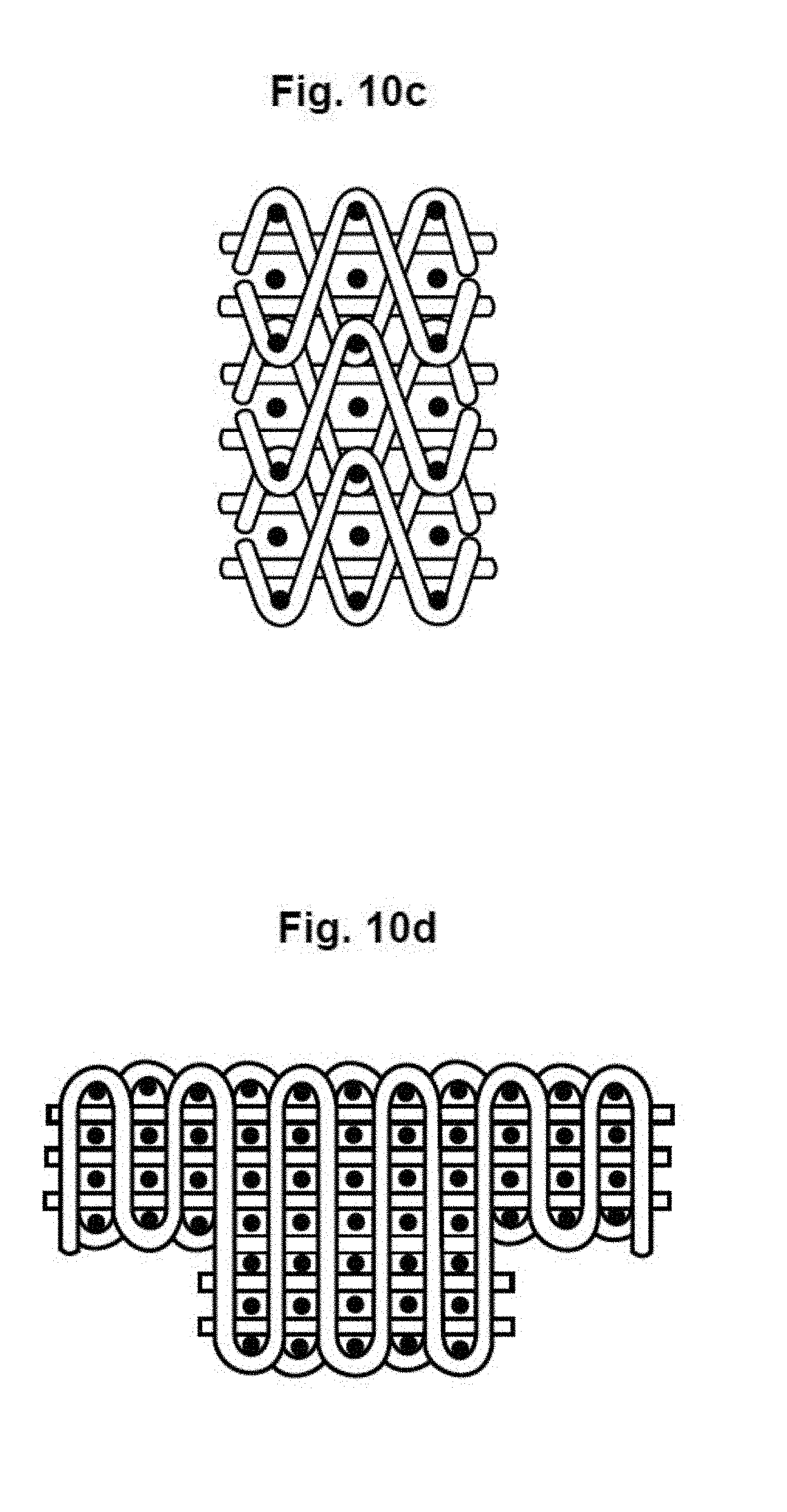
XML
uspto.report is an independent third-party trademark research tool that is not affiliated, endorsed, or sponsored by the United States Patent and Trademark Office (USPTO) or any other governmental organization. The information provided by uspto.report is based on publicly available data at the time of writing and is intended for informational purposes only.
While we strive to provide accurate and up-to-date information, we do not guarantee the accuracy, completeness, reliability, or suitability of the information displayed on this site. The use of this site is at your own risk. Any reliance you place on such information is therefore strictly at your own risk.
All official trademark data, including owner information, should be verified by visiting the official USPTO website at www.uspto.gov. This site is not intended to replace professional legal advice and should not be used as a substitute for consulting with a legal professional who is knowledgeable about trademark law.