Thermally Treated Metallic Materials And Related Methods
Bookbinder; Dana Craig ; et al.
U.S. patent application number 16/073899 was filed with the patent office on 2019-02-07 for thermally treated metallic materials and related methods. The applicant listed for this patent is CORNING INCORPORATED. Invention is credited to Dana Craig Bookbinder, Theresa Chang, Jeffrey John Domey, Peter Joseph Lezzi, Richard Orr Maschmeyer, John Christopher Thomas, Kevin Lee Wasson.
| Application Number | 20190040491 16/073899 |
| Document ID | / |
| Family ID | 58213322 |
| Filed Date | 2019-02-07 |
| United States Patent Application | 20190040491 |
| Kind Code | A1 |
| Bookbinder; Dana Craig ; et al. | February 7, 2019 |
THERMALLY TREATED METALLIC MATERIALS AND RELATED METHODS
Abstract
A thermally treated metal sheet or article as well as processes and systems for making the thermally treated sheet or article is provided. The process comprises heating and/or cooling the metal sheet by non contact thermal conduction for sufficiently long to provide a desired microstructure and mechanical properties. The process results in thermally treated metal sheets.
| Inventors: | Bookbinder; Dana Craig; (Corning, NY) ; Chang; Theresa; (Painted Post, NY) ; Domey; Jeffrey John; (Elmira, NY) ; Lezzi; Peter Joseph; (Corning, NY) ; Maschmeyer; Richard Orr; (Corning, NY) ; Thomas; John Christopher; (Elmira, NY) ; Wasson; Kevin Lee; (Elmira, NY) | ||||||||||
| Applicant: |
|
||||||||||
|---|---|---|---|---|---|---|---|---|---|---|---|
| Family ID: | 58213322 | ||||||||||
| Appl. No.: | 16/073899 | ||||||||||
| Filed: | January 27, 2017 | ||||||||||
| PCT Filed: | January 27, 2017 | ||||||||||
| PCT NO: | PCT/US2017/015283 | ||||||||||
| 371 Date: | July 30, 2018 |
Related U.S. Patent Documents
| Application Number | Filing Date | Patent Number | ||
|---|---|---|---|---|
| 62288695 | Jan 29, 2016 | |||
| Current U.S. Class: | 1/1 |
| Current CPC Class: | C21D 1/613 20130101; C22C 38/002 20130101; C22F 1/043 20130101; C22C 21/02 20130101; C22F 1/10 20130101; C21D 1/53 20130101; C21D 9/567 20130101; C21D 2211/002 20130101; C22C 19/07 20130101; C22C 38/44 20130101; C21D 2201/03 20130101; C22F 1/004 20130101; C22C 38/02 20130101; C22F 1/002 20130101; C22F 1/08 20130101; C21D 2211/008 20130101; C22C 38/06 20130101; C22C 19/055 20130101; C22C 38/50 20130101; C21D 9/63 20130101; C22C 38/001 20130101; C22C 38/04 20130101 |
| International Class: | C21D 9/63 20060101 C21D009/63; C21D 9/567 20060101 C21D009/567; C21D 1/613 20060101 C21D001/613; C21D 1/53 20060101 C21D001/53; C22F 1/043 20060101 C22F001/043; C22F 1/08 20060101 C22F001/08; C22F 1/10 20060101 C22F001/10; C22F 1/00 20060101 C22F001/00 |
Claims
1. A process for thermally treating metallic materials comprising: heating and/or cooling a metallic article, the article supported with gas during the heating and/or cooling; wherein the article is heated by transferring thermal energy from a heat source to the article across a heating gap between the heat source and the article such that more than 20% of the thermal energy leaving the heat source crosses the heating gap and is received by the article; wherein the article is cooled by transferring thermal energy from the article to a heat sink across a cooling gap between the article and the heat sink such that more than 20% of the thermal energy leaving the article crosses the cooling gap and is received by the heat sink.
2. The process of claim 1, wherein more than 50% of the thermal energy leaving the heat source or the article crosses the heating gap or the cooling gap, respectively, and is received by the article or the heat sink, respectively.
3. The process of claim 2, wherein the heating gap or the cooling gap has an average thickness between an outer surface of the heat source and an adjacent surface of the article or the adjacent surface of the article and an outer surface of the heat sink that is less than about 10 mm, 5 mm, 2 mm 1 mm, 800 .mu.m, 600 .mu.m, 400 .mu.m, or 200 .mu.m.
4. The process of claim 3, wherein a heat transfer rate from the heat source to the article during heating or from the article to the heat sink during cooling is greater than about 50 kW/m.sup.2, 100 kW/m.sup.2, 150 kW/m.sup.2, 200 kW/m.sup.2, 250 kW/m.sup.2, 300 kW/m.sup.2, 350 kW/m.sup.2, 450 kW/m.sup.2, 550 kW/m.sup.2, 650 kW/m.sup.2, 750 kW/m.sup.2, 1000 kW/m.sup.2, or 1200 kW/m.sup.2 for the area of the outer surface of the heat source or for the area of the outer surface of the article, respectively.
5. The process of claim 4, wherein the article is a sheet having a length, a width and a thickness, wherein the thickness is greater than about 0.1 mm and less than 2 mm, and at least one of the width and the length are greater than 5 times the thickness.
6. The process of claim 4, wherein the heating gap or cooling gap is a gas gap with a gap area, wherein a total flow rate of gas into the gas gap is greater than zero and less than 2 k/gCp per square meter of gap area, where k is the thermal conductivity of a gas within the gas gap evaluated in the direction of heat conduction, g is the distance between the heated article and the heat sink surface, and Cp is the specific heat capacity of the gas within the gas gap.
7. The process of claim 4, wherein the metallic material is selected from the group consisting of a polycrystalline metallic material, a single crystal metallic material and a metallic glass material.
8. The process of claim 4, wherein the metallic material is a polycrystalline metallic material selected from the group consisting of a pure metal and an alloy.
9. The process of claim 4 any of claims 1 8, wherein the polycrystalline metallic material is the alloy selected from the group consisting of an aluminum alloy, a copper alloy, an iron alloy and a nickel alloy.
10. The process of claim 9, wherein the alloy is an aluminum alloy that is heated by the heat source and heating of the aluminum alloy results in precipitation strengthening of the article.
11. The process of claim 9, wherein the metallic material is a cold worked aluminum alloy that is heated by the heat source, wherein a microstructure of the heated cold work aluminum alloy undergoes recrystallization.
12. The process of claim 9, wherein the metallic material is a copper alloy that is heated by the heat source and heating of the copper alloy results in precipitation strengthening of the article.
13. The process of claim 9, wherein the metallic material is a cold worked copper alloy that is heated by the heat source, wherein a microstructure of the heated cold work copper alloy undergoes recrystallization.
14. The process of claim 9, wherein the metallic material is a cold worked iron alloy that is heated by the heat source, wherein a microstructure of the heated cold worked iron alloy undergoes recrystallization.
15. The process of claim 9, wherein the metallic material is an iron alloy that is heated by the heat source to an annealing temperature and cooled by the heat sink at a cooling rate that provides a microstructure with a desired amount of pearlite.
16. The process of claim 9, wherein the metallic material is an iron alloy that is heated by the heat source to an appropriate austenizing temperature for the iron alloy and cooled by the heat sink at a cooling rate that provides a microstructure with a desired amount of bainite and/or martensite.
17. The process of claim 16, wherein the cooling rate provides a microstructure with no pearlite.
18. The process of claim 9, wherein the metallic material is a cold worked nickel alloy that is heated by the heat source for recrystallization of the article and cooled by the heat sink for controlled grain growth of the article after recrystallization.
19. The process of claim 9, wherein the metallic material is a nickel alloy that is heated by the heat source to an appropriate aging treatment temperature that provides precipitation strengthening of the article via precipitation of at least one of gamma prime precipitates, carbide precipitates, nitride precipitates and carbonitride precipitates.
20. The process of claim 9, wherein the metallic material is a metallic glass that is heated such that a surface region of the article is recrystallized and an inner region is not recrystallized.
21. The process of claim 1, wherein the heating occurs in a heating zone configured to chemically alter a surface region of the article.
22. The process of claim 21, wherein the heating zone is configured to provide chromizing, carburizing, boriding, nitriding, aluminizing, silicon izing, and combinations thereof, to the surface region of the article.
23. A process for thermally treating metallic materials comprising: heating and/or cooling a metallic material article, the article supported with gas during the heating and/or cooling; wherein the article is heated by transferring thermal energy from a heat source to the article across a heating gap between the heat source and the article such that at least 50% of the thermal energy leaving the heat source crosses the heating gap and is received by the article; wherein the article is cooled by transferring thermal energy from the article to a heat sink across a cooling gap between the article and the heat sink such that at least 50% of the thermal energy leaving the article crosses the cooling gap and is received by the heat sink; wherein the heating gap or the cooling gap has an average thickness between an outer surface of the heat source and an adjacent surface of the article or the article and an outer surface of the heat sink that is less than about 10 mm; wherein a heat transfer rate from the heat source to the article during heating or from the article to the heat sink during cooling is greater than about 1000 kW/m.sup.2.
24. A thermally treated metallic material article comprising: an article made from a metallic material selected from the group consisting of an Al-base alloy, a Cu-base alloy, a Ni-base alloy, an Fe-base alloy and a Ti alloy; the metallic material article having a microstructure as a result of heating and/or cooling the metallic material while the metallic material article is supported with a gas during the heating and/or cooling; the metallic material article heated by transferring thermal energy from a heat source to the metallic material article across a heating gap between the heat source and the metallic material article such that more than 20% of the thermal energy leaving the heat source crosses the heating gap and is received by the metallic material article; the metallic material article cooled by transferring thermal energy from the metallic material article to a heat sink across a cooling gap between the metallic material article and the heat sink such that more than 20% of the thermal energy leaving the metallic material article crosses the cooling gap and is received by the heat sink; the microstructure selected from the group consisting of a solid-solution strengthened microstructure, a precipitation strengthened microstructure, a ferrite plus pearlite microstructure, a ferrite plus bainite and/or martensite microstructure, a ferrite plus retained austenite microstructure and a ferrite with no pearlite microstructure.
25. The thermally treated metallic material article of claim 24, wherein the article is made from an Fe-base alloy with a ferrite plus martensite microstructure with less than 6 vol % bainite and has a tensile strength of at least 590 MPa, a yield strength of at least 330 MPa and a total elongation to failure of at least 18%.
26. The thermally treated metallic material article of claim 24, wherein the article is made from an Al-base alloy with an age hardened microstructure and an average room temperature tensile strength of 45,000 psi, an average room temperature yield strength of 40,000 psi, and an average room temperature elongation to failure of 12%.
27. The thermally treated metallic material article of claim 24, wherein the article is made from an Ni-base alloy with an age hardened microstructure and has an average room temperature tensile strength of 1335 MPa, an average room temperature yield strength of 910 MPa, and an average room temperature elongation to failure of 26.6%.
Description
[0001] This application claims the benefit of priority under 35 U.S.C. .sctn. 119 of U.S. Provisional Application Ser. No. 62/288,695 filed on Jan. 29, 2016, the content of which is relied upon and incorporated herein by reference in its entirety.
BACKGROUND
Field
[0002] The disclosure relates generally to thermally treated metallic materials and to related methods and systems for the thermal treatment of metals and alloys.
Technical Background
[0003] In the thermal treatment of metallic materials such as pure metals, alloys, intermetallics and metallic glasses, a variety of thermal and/or thermomechanical processes are used to provide desired combinations of microstructure, mechanical properties, physical properties and/or surface finishes. Particularly, metallic materials can be thermally treated and/or thermomechanically treated to produce recrystallization of the metallic material's microstructure, stress relief of a metallic material article and/or desired second phase morphology within a host matrix. Such thermal treatments typically include heating of a metallic material article to an elevated temperature, holding the metallic material article at the elevated temperature for a desired length of time and then cooling the metallic material article. In some processes, a controlled heating rate employed to heat the metallic component article to the elevated temperature and/or cooling a controlled cooling rate to cool the metallic material article is desired.
[0004] Current thermal treatment of metallic material articles, particularly in commercial thermal treatment processers, use large heating furnaces, long cooling (runout) tables which require large amounts energy to provide sufficient heat and cooling liquid to provide sufficient cooling rates. In addition, rapidly quenching metallic material articles from the elevated temperature to a desired lower temperature can be a problematic when attempting to move metallic material articles from a heated furnace (heating zone) to a quench station (cooling zone). Accordingly, apparatuses and methods that provide thermal treatments to metallic material articles while reducing energy consumption and increasing ease of movement between heating zones and cooling zones would be desirable.
SUMMARY
[0005] This disclosure relates, in part, to thermally treated metallic material articles, and to methods, processes, and systems that thermally treat metallic material articles. In various embodiments, the process and method of the current disclosure heats and/or cools an article formed from a metallic material (article), the article supported with gas during the heating and/or cooling. The article is heated by transferring thermal energy from a heat source to the article across a heating gap between the heat source and the article such that more than 20% of the thermal energy leaving the heat source crosses the heating gap and is received by the article. The article is heated to and held at a desired elevated temperature for a desired amount of time. Thereafter, the article is allowed to cool. In embodiments, the article is allowed to air cool. In other embodiments, the article is cooled by transferring thermal energy from the article to a heat sink across a cooling gap between the article and the heat sink such that more than 20% of the thermal energy leaving the heated article crosses the cooling gap and is received by the heat sink. In embodiments, the article is supported with gas during heating and more than half of the thermal energy leaving the heat source crosses the heating gap is received by the article. The article can also be supported with gas during cooling and more than half of the thermal energy leaving the article crosses the cooling gap is received by the heat sink. The heating gap or the cooling gap can have an average thickness between an outer surface of the heat source and the article or the article and an outer surface of the heat sink surface, respectively, that is less than 10 millimeters (mm), 5 mm, 2 mm 1 mm, 800 micrometers (.mu.m), 600 .mu.m, 400 .mu.m, or 200 .mu.m. In embodiments, a heat transfer rate from the heat source to the article during heating, or from the article to the heat sink during cooling, is greater than 50 kilowatts per square meter (kW/m.sup.2), greater than 100 kW/m.sup.2, greater than 150 kW/m.sup.2, greater than 200 kW/m.sup.2, greater than 250 kW/m.sup.2, greater than 300 kW/m.sup.2, greater than 350 kW/m.sup.2, greater than 450 kW/m.sup.2, greater than 550 kW/m.sup.2, greater than 650 kW/m.sup.2, greater than 750 kW/m.sup.2, greater than 1000 kW/m.sup.2, or greater than 1200 kW/m.sup.2 for the area of the outer surface of the heat source, or for the area of the outer surface of the article, respectively.
[0006] The article can be in the form of a sheet, a cylindrical rod, a hexagonal rod, and the like. When the article is in the form of a sheet, the article has a length, a width, and a thickness. In embodiments, the thickness of the sheet is less than 3 mm, less than 2 mm, less than 1.5 mm, less than 1.0 mm, less than 0.5 mm, less than about 0.25 mm, less than about 0.1 mm, less than 0.08 mm, less than 0.06 mm, or less than 0.04 mm. At least one of the width and the length are greater than five times the thickness of the sheet. When the article is in the form of a rod, the rod has an average diameter and a length. In embodiments, the diameter of the rod is less than 10 mm, less than 9 mm, less than 8 mm, less than 7 mm, less than 6 mm, less than 5 mm, less than 4 mm, less than 3 mm, less than 2 mm, less than 1 mm, less than 0.8 mm, less than 0.6 mm, less than 0.4 mm, less than 0.2 mm or less than 0.1 mm.
[0007] The heating gap or cooling gap can be a gas gap with a gap area and a total mass flow rate of gas into the gas gap is greater than 0 and less than 2 k/gCp per square meter of gap area where k is the thermal conductivity of a gas within the gas gap evaluated in the direction of heat conduction, g is the distance between the heated article and the heat sink surface, and Cp is the specific heat capacity of the gas within the gas gap.
[0008] The metallic material can be a pure metal or an alloy and the pure metal or alloy can be polycrystalline, single crystal, or metallic glass. The pure metal can be a commercial pure metal such as commercial pure aluminum (Al), copper (Cu), chromium (Cr), nickel (Ni), niobium (Nb), iron (Fe), magnesium (Mg), molybdenum (Mo), silver (Ag), tantalum (Ta), titanium (Ti), tungsten (W) zirconium (Zr), gold (Au), platinum (Pt) or any other commercially available pure metal. The alloy can be an Al-base alloy, a Cu-base alloy, a Cr-base alloy, a Ni-base alloy, a Nb-base alloy, an Fe-base alloy, a Mg-base alloy, a Mo-base alloy, a Ag-base alloy, a Ta-base alloy, a Ti-base alloy, a W-base alloy, a Zr-base alloy, a Au-base alloy or another known alloy.
[0009] In embodiments, the article is made from an Al-base alloy and the Al-base alloy article is solution heat treated, quenched and aged in order to provide a precipitation strengthened (also known as precipitation hardened or age hardened) article with reduced residual stresses. In addition, the Al-base alloy article can be subjected cold working and then heated by the heat source such that recrystallization of the cold worked Al-base alloy article microstructure occurs. The recrystallized Al-base alloy article can be controllably cooled to prevent undesired grain growth of the recrystallized Al-base alloy article microstructure.
[0010] In embodiments, the article is made from a Cu-base alloy article and the Cu-base alloy article is solution heat treated, quenched and aged in order to provide a precipitation strengthened article with reduced residual stresses. In addition, the Cu-base alloy article can be subjected cold working and then heated by the heat source such that recrystallization of the cold worked Cu-base alloy article microstructure occurs. The recrystallized Cu-base alloy article can be controllably cooled to prevent undesired grain growth of the recrystallized Cu-base alloy article microstructure.
[0011] In embodiments, the article is made from an Fe-base alloy and the Fe-base alloy article is solution annealed such that the microstructure of the Fe-base alloy is completely austenite and then cooled to provide a microstructure with ferrite and a desired amount of pearlite, including no pearlite. In other embodiments, the Fe-base alloy article is solution annealed such that the microstructure of the Fe-base alloy is completely austenite and then cooled to provide a microstructure with ferrite and a desired amount of bainite and/or martensite. The solution annealed Fe-base alloy article can be cooled such retained austenite can be present in the Fe-base alloy article's microstructure. The Fe-base alloy article can be subjected cold working and then heated by the heat source such that recrystallization of the cold worked Fe-base alloy article microstructure occurs. The recrystallized Fe-base alloy article can be controllably cooled to prevent undesired grain growth of the recrystallized Fe-base alloy article microstructure.
[0012] In embodiments, the article is made from a Ni-base alloy and the Ni-base alloy article is solution annealed such that the microstructure of the Ni-base alloy is completely austenitic (face centered cubic--FCC) and then cooled to provide a microstructure with desired second phase precipitates. Such second phases precipitates can include Ni.sub.3Al (gamma prime) precipitates, carbide precipitates, nitride precipitates and/or carbonitride precipitates. The Ni-base alloy article can be subjected cold working and then heated by the heat source such that recrystallization of the cold worked Ni-base alloy article microstructure occurs. The recrystallized Ni-base alloy article can be controllably cooled to prevent undesired grain growth of the recrystallized Ni-base alloy article microstructure. The article can be made from other types of alloys and heat treated and cooled to provide a desired article microstructure. It should be appreciated that the microstructure of an alloy article is closely linked to the article's mechanical properties. Accordingly, an alloy article can be heated treated and cooled to provide a desired combination of strength and ductility.
[0013] The process can include heating of the metallic material article in a heating zone configured to chemically alter a surface region of the article. For example, the heating zone can include chemical vapor deposition (CVD) equipment and/or plasma deposition equipment that can chemically alter the surface region of the article. The surface region of the article can be chemically altered such as by coating with, impregnation and/or diffusion of elements such as nitrogen (nitriding), boron (boriding), carbon (carburizing), and combinations thereof.
[0014] Additional features and advantages will be set forth in the detailed description that follows, and, in part, will be readily apparent to those skilled in the art from the description or recognized by practicing the embodiments as described in the written description and claims hereof, as well as the appended drawings.
[0015] It is to be understood that both the foregoing general description and the following detailed description are merely exemplary, and are intended to provide an overview or framework to understand the nature and character of the claims.
[0016] The accompanying drawings are included to provide a further understanding and are incorporated in and constitute a part of this specification. The drawings illustrate one or more embodiments, and together with the description serve to explain principles and the operation of the various embodiments.
BRIEF DESCRIPTION OF THE DRAWINGS
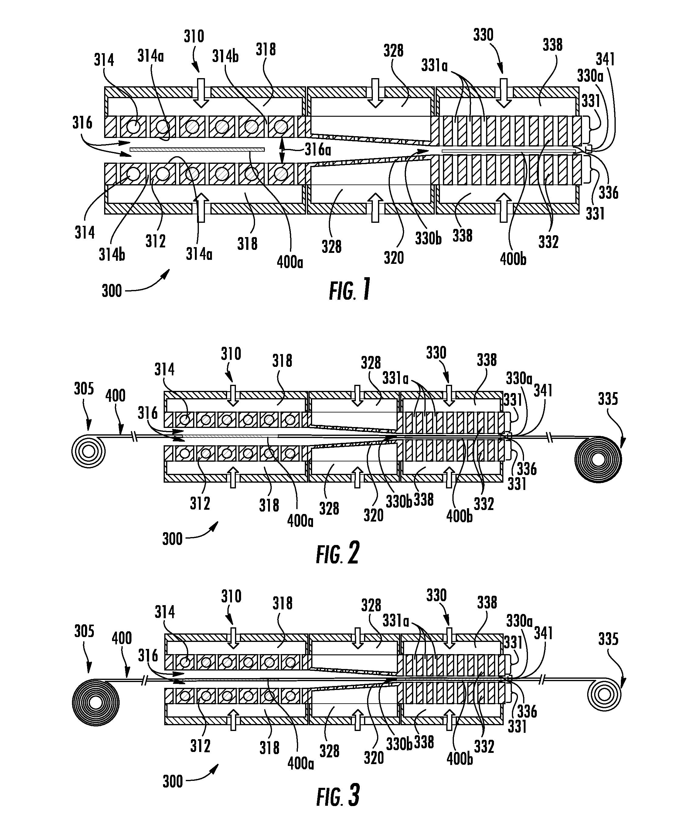
[0017] FIG. 1 is a diagrammatic cross-section of a thin metallic material sheet being cooled by conduction more than by convection using an inventive thermal treatment system according to an exemplary embodiment;
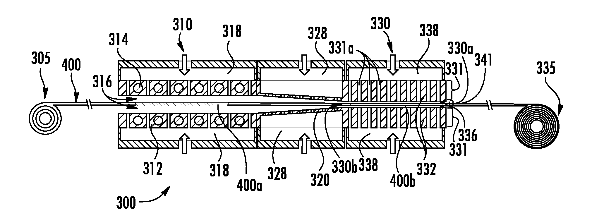
[0018] FIG. 2 is a diagrammatic cross-sectional diagram of metallic material thin sheet being heated and cooled by conduction more than by convection in a continuous manner using an inventive thermal treatment system according to an exemplary embodiment;
[0019] FIG. 3 is a diagrammatic cross-sectional diagram of metallic material thin sheet being heated and cooled by conduction more than by convection in a continuous manner according to an exemplary embodiment;
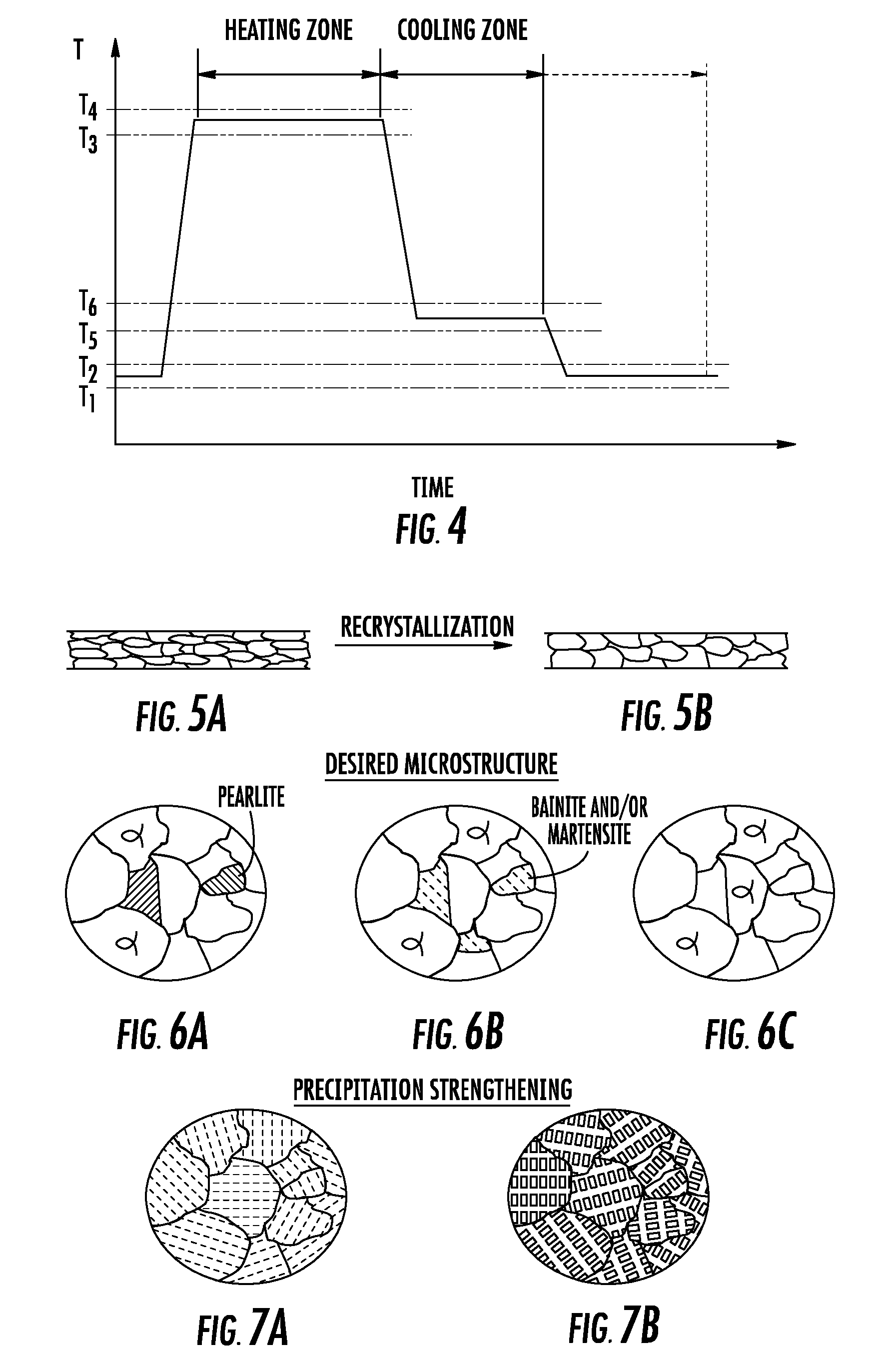
[0020] FIG. 4 is a graph showing temperature versus time for heating and cooling of metallic material thin sheet according to embodiments disclosed in the present disclosure;
[0021] FIG. 5A is a schematic cross-section of a cold worked metallic material thin sheet before recrystallization;
[0022] FIG. 5B is a schematic cross-section of the metallic material thin sheet of FIG. 4A after recrystallization;
[0023] FIG. 6A is a schematic illustration of an iron alloy having a desired amount of pearlite and produced according to an exemplary embodiment;
[0024] FIG. 6B is a schematic illustration of an iron alloy microstructure with a desired amount of bainite and martensite produced according to an exemplary embodiment;
[0025] FIG. 6C is a schematic illustration of an iron alloy microstructure having no pearlite;
[0026] FIG. 7A is a schematic illustration of an aluminum alloy microstructure having been precipitation strengthened according to an exemplary embodiment;
[0027] FIG. 7B is a schematic illustration of a nickel alloy microstructure having been precipitation strengthened according to an exemplary embodiment;
[0028] FIG. 8 is a schematic cross-section of a metallic glass thin sheet with surface regions having a recrystallized microstructure in an inner region with a glass microstructure produced according to an exemplary embodiment; and
[0029] FIG. 9 is a schematic cross-sectional diagram of an apparatus configured to chemically alter a surface region of a metallic material thin sheet article according to an exemplary embodiment.
DETAILED DESCRIPTION
[0030] Applicant has recognized a need for improvements in thermal treatment of metallic materials, both in methods and systems for thermally treating metallic materials and the resulting thermally treated metallic materials themselves. For example, thin sheets of metallic materials are useful for a number of applications, including use in heat exchangers, aerospace applications, cookware, cutlery, heat treating equipment, alternative energy components, and building materials. Metallic materials, the term herein including pure metals, alloys, intermetallics, and metallic glasses, can be processed to have a wide range of microstructures and mechanical properties. Metallic materials, particularly alloys, can provide high strength and excellent ductility compared to ceramics and glasses. In addition, metallic materials are typically electrically conductive and are used in electrical applications.
[0031] Traditional thermal treatment of metallic materials typically includes placing a metallic material article (article) in a furnace at an elevated temperature for a given amount of time and then removing the article form the furnace and cooled. In the event that the article has been subjected to cold working, the thermal treatment of the article can result in recrystallization of the article's microstructure. The thermal treatment of the article can also reduce residual stress within the article without recrystallization of the article's microstructure. When the article is made from a metal or alloy that has a high temperature phase and a different low temperature phase, e.g. iron or steel with an austenitic high temperature phase (.gamma.) and a ferritic low temperature phase (.alpha.) thermal treatment of the article can provide an article microstructure with the ferritic low temperature phase and additional metastable phases. In addition, heating and controlled cooling of the article can provide a desired density and spatial location of the one or more metastable phases. However, traditional thermal treatment of articles typically involves large furnaces that use significant amounts of energy for heating. Additionally, such furnaces may provide a reducing atmosphere for thermal treatment of the articles and this use large amounts of reducing gases such as hydrogen gas.
[0032] Therefore, a need exists for systems and methods for thermally treating articles that significantly reduce energy and/or reducing gas requirements. Specifically, processes and systems discussed herein thermally treat articles with a reduced energy consumption of at least 50% compared to traditional thermal treating systems. When a reducing gas is used during thermal treatment of a given type of classification of articles, the methods and systems described herein reduce the amount of reducing gas needed by more than 50% compared to traditional thermal treating systems.
[0033] The processes and systems described herein thermally treat an article by heating and/or cooling the article while it is supported with gas. In some embodiments the gas can be a moving and, in further embodiments, capable of moving the article. The article can be heated by transferring thermal energy from a heat source to the article across a heating gap between the heat source and the article such that more than 20% of the thermal energy leaving the heat source crosses the heating gap and can be received by the article. Also, the article can be cooled by transferring thermal energy from the article to a heat sink across a cooling gap between the article and the heat sink such that more than 20% of the thermal energy leaving the article crosses the cooling gap and can be received by the heat sink. In embodiments, more than 50% of the thermal energy leaving the heat source or the article crosses the heating gap or the cooling gap, respectively, and can be received by the article component or the heat sink, respectively. The heating gap or the cooling gap can have an average thickness between an outer surface of the heat source and the article or between the article and an outer surface of the heat sink that can be less than 200 microns, less than 180 microns, less than 160 microns, less than 140 microns, less than 120 microns, less than 100 microns, less than 80 microns, less than 60 microns, less than 40 microns or less than 20 microns. A heat transfer rate from the heat source to the article during heating or from the article to the heat sink during cooling can be greater than 50 kilowatts per square meter (kW/m.sup.2), greater than 100 kW/m.sup.2, greater than 150 kW/m.sup.2, greater than 200 kW/m.sup.2, greater than 250 kW/m.sup.2, greater than 300 kW/m.sup.2, greater than 350 kW/m.sup.2, greater than 450 kW/m.sup.2, greater than 550 kW/m.sup.2, greater than 650 kW/m.sup.2, greater than 750 kW/m.sup.2, greater than 1000 kW/m.sup.2, or greater than 1200 kW/m.sup.2 for the area of the outer surface of the heat source, or for the area of the outer surface of the article, respectively.
[0034] The article can be in the form of a sheet, a cylindrical rod, a hexagonal rod, and the like. When the article is in the form of a sheet, the article has a length, a width, and a thickness. In embodiments, the thickness of the sheet can be less than 3 mm, less than 2 mm, less than 1.5 mm, less than 1.0 mm, less than 0.5 mm, less than about 0.25 mm, less than about 0.1 mm, less than 0.08 mm, less than 0.06 mm, or less than 0.04 mm. At least one of the width and the length are greater than five times the thickness of the sheet. When the article is in the form of a rod, the rod has an average diameter and a length. In embodiments, the diameter of the rod can be less than 10 mm, less than 9 mm, less than 8 mm, less than 7 mm, less than 6 mm, less than 5 mm, less than 4 mm, less than 3 mm, less than 2 mm, less than 1 mm, less than 0.8 mm, less than 0.6 mm, less than 0.4 mm, less than 0.2 mm or less than 0.1 mm.
[0035] The heating gap or cooling gap can be a gas gap with a gap area and the total mass flow rate of gas into the gas gap can be greater than zero and less than 2 k/gCp per square meter of gap area, where k is the thermal conductivity of a gas within the gas gap evaluated in the direction of heat conduction, g is the distance between the heat source and the article or between the article and the heat sink surface, and Cp is the specific heat capacity of the gas within the gas gap.
[0036] The metallic material can be a pure metal or an alloy and the pure metal or alloy can be polycrystalline, single crystal, or metallic glass. The pure metal can be a commercial pure metal such as commercial pure aluminum (Al), copper (Cu), chromium (Cr), nickel (Ni), niobium (Nb), iron (Fe), magnesium (Mg), molybdenum (Mo), silver (Ag), tantalum (Ta), titanium (Ti), tungsten (W) zirconium (Zr), gold (Au), platinum (Pt) or any other commercially available pure metal. The alloy can be an Al-base alloy, a Cu-base alloy, a Cr-base alloy, a Ni-base alloy, a Nb-base alloy, an Fe-base alloy, a Mg-base alloy, a Mo-base alloy, a Ag-base alloy, a Ta-base alloy, a Ti-base alloy, a W-base alloy, a Zr-base alloy, a Au-base alloy or another known alloy.
[0037] In embodiments, the article can be made from an Al-base alloy and the Al-base alloy article can be solution heat treated and quenched in order to provide a precipitation strengthened (also known as precipitation hardened or age hardened) article with reduced residual stresses. In addition, the Al-base alloy article can be subjected cold working and then heated by the heat source such that recrystallization of the cold worked Al-base alloy article microstructure occurs. The recrystallized Al-base alloy article can be controllably cooled to prevent undesired grain growth of the recrystallized Al-base alloy article microstructure.
[0038] In embodiments, the article can be made from a Cu-base alloy article and the Cu-base alloy article can be solution heat treated, quenched and aged in order to provide a precipitation strengthened article with reduced residual stresses. In addition, the Cu-base alloy article can be subjected cold working and then heated by the heat source such that recrystallization of the cold worked Cu-base alloy article microstructure occurs. The recrystallized Cu-base alloy article can be controllably cooled to prevent undesired grain growth of the recrystallized Cu-base alloy article microstructure.
[0039] In embodiments, the article can be made from an Fe-base alloy and the Fe-base alloy article can be solution annealed such that the microstructure of the Fe-base alloy can be completely austenite and then cooled to provide a microstructure with ferrite and a desired amount of pearlite, including no pearlite. In other embodiments, the Fe-base alloy article can be solution annealed such that the microstructure of the Fe-base alloy can be completely austenite and then cooled to provide a microstructure with ferrite and a desired amount of bainite and/or martensite. The solution annealed Fe-base alloy article can be cooled such retained austenite can be present in the Fe-base alloy article's microstructure. The Fe-base alloy article can be subjected cold working and then heated by the heat source such that recrystallization of the cold worked Fe-base alloy article microstructure occurs. The recrystallized Fe-base alloy article can be controllably cooled to prevent undesired grain growth of the recrystallized Fe-base alloy article microstructure. For the purposes of the present disclosure, the term "solution annealed" refers to a thermal treatment that produces a solid solution of alloy elements in a high temperature matrix phase. It should be appreciated that the high temperature matrix phase can be the same phase as a low temperature matrix phase, e.g. face centered cubic (FCC) austenite for Ni-base alloys, or can be a different phase from the low temperature phase, e.g. FCC austenite versus BCC ferrite for Fe-base alloys.
[0040] In embodiments, the article can be made from a Ni-base alloy and the Ni-base alloy article can be solution annealed such that the microstructure of the Ni-base alloy can be completely austenitic (face centered cubic--FCC) and then cooled to provide a microstructure with desired second phase precipitates. Such second phases precipitates can include Ni.sub.3Al (gamma prime) precipitates, carbide precipitates, nitride precipitates and/or carbonitride precipitates. The Ni-base alloy article can be subjected cold working and then heated by the heat source such that recrystallization of the cold worked Ni-base alloy article microstructure occurs. The recrystallized Ni-base alloy article can be controllably cooled to prevent undesired grain growth of the recrystallized Ni-base alloy article microstructure. The article can be made from other types of alloys and heat treated and cooled to provide a desired article microstructure. It should be appreciated that the microstructure of an alloy article can be closely linked to the article's mechanical properties. Accordingly, an alloy article can be heated treated and cooled to provide a desired combination of strength and ductility.
[0041] The process can include heating of the metallic material article in a heating zone configured to chemically alter a surface region of the article. For example, the heating zone can include chemical vapor deposition (CVD) equipment and/or plasma deposition equipment that can chemically alter the surface region of the article. The surface region of the article can be chemically altered such as by coating with, impregnation and/or diffusion of elements such as nitrogen (nitriding), boron (boriding), carbon (carburizing), and combinations thereof.
[0042] By way of example, FIG. 1 shows an exemplary embodiment of a metal thermal treatment system 300 according to this disclosure. FIG. 1 shows a schematic cross-sectional diagram of the system 300, in which an article (sheet) can be heated via conduction of heat from a heat source to the article and cooled via conduction of heat from the article, through a gas into a conductive heat sink. The metal thermal treatment system 300 includes a hot zone 310, a cold zone 330, and a transition gas bearing 320. Transition gas bearing 320 moves or directs the article (e.g., metallic material sheet (sheet) 400a) from the hot zone 310 to the cold zone 330 such that no contact or substantially no contact occurs between the sheet and the bearings. The hot zone 310 has gas bearings 312 each fed from a hot zone plenum 318, and the bearings 312 have heat sources 314 inserted into holes through the bearings 312, which serve to heat the hot zone gas bearings 312 to a desired thermal treatment process temperature. The heat sources 314 can be electrically resistive heat sources or induction heating heat sources. In embodiments, the heat sources 314 may have an outer surfaces 314a that face the channel 316 and the outer surfaces 314a may provide infrared heating. A sheet (hot zone) 400a can be kept between the hot zone gas bearings 312 for a duration long enough to bring it to a desired thermal treatment temperature (e.g., a stress relief temperature, a solution annealing temperature, a high temperature phase annealing temperature, an age hardening temperature, etc.).
[0043] In some embodiments, heating the article in the hot zone may be done predominantly via conduction of heat from a heat sink through a thin gas barrier. The conductive heating processes used in the hot zone can be similar to, but the reverse of the cooling processes described herein (e.g., pushing heat into the article). As shown in FIG. 1, the hot zone 310 includes the one or more heat sources 314 disposed adjacent to the channel 316. Where two heat sources are utilized, such heat sources may be disposed on opposite sides of the channel 316, facing each other across a channel gap 316a between the outer surfaces 314a. In some embodiments, the heat sources include a plurality of apertures 314b which form part of the gas bearing 312, and the outer surfaces 314a of the hot gas bearings 312 of the hot zone 310 serve as the two heat source surfaces. Due to the low gas flow rate within channel 316 and the small size that can be provided for the channel gap 316a, sheet 400a can be heated within hot zone 310 primarily by conduction of heat from the heat sources 314 across the channel gap 316a and into the sheet 400a, without the sheet 400a touching the heat source outer surfaces 314a.
[0044] In some embodiments, the heat sources and/or the surfaces thereof may be segmented. In some embodiments, the heat sources may be porous, and in such embodiments, the apertures through which the gas for gas bearings 312 can be delivered are the pores of the porous heat sinks. The plurality of apertures 314b, a gas source and the channel gap 316a may be in fluid communication. In some embodiments, the gas flows through the apertures 314b to form gas cushions, layers or bearings in the channel gap 316a. The gas cushions of some embodiments prevent the sheet 400a from contacting the heat source 314 surfaces. The gas also serves as the gas through which the sheet 400a can be heated by conduction more than by convection.
[0045] In some embodiments, the gas flowed through the apertures 314b heats the heat sources 314. In some embodiments, the gas flowed through the apertures both facilitates heat conduction, from the heat source 314, across the gap 316a, into the sheet 400a, and also heats the heat sources 314. In some instances, a separate gas or liquid may be used to heat the heat sources 314. For instance, the heat sources 314 may include passages (not shown), for flowing a heating gas or liquid therethrough to heat the heat sources 314. The passages can be enclosed.
[0046] Where two heat sources are used (i.e., a first heat source and the second heat source), one or more gas sources may be used to provide a gas to the channel gap 316a. The gas sources may include the same gas as one another or different gases. The channel gap 316a may, therefore, include one gas, a mixture of gases from different gas sources, or the same gas source. Exemplary gases include air, nitrogen, carbon dioxide, helium or other noble gases, hydrogen and various combinations thereof. The gas may be described by its thermal conductivity when it enters the channel 316 just before it begins to conductively heat the sheet 400a. In some instances, the gas may have a thermal conductivity of about (e.g., plus or minus 1%) 0.02 W/(mK) or greater, about 0.025 W/(mK) or greater, about 0.03 W/(mK) or greater, about 0.035 W/(mK) or greater, about 0.04 W/(mK) or greater, about 0.045 W/(mK) or greater, about 0.05 W/(mK) or greater, about 0.06 W/(mK) or greater, about 0.07 W/(mK) or greater, about 0.08 W/(mK) or greater, about 0.09 W/(mK) or greater, about 0.1 W/(mK) or greater, about 0.15 W/(mK) or greater, or about 0.2 W/(mK) or greater).
[0047] The processes and systems described herein allow for high heat transfer rates which, as discussed above, allow for rapid and controlled heating within sheet, and allow for rapid, localized and controlled heating of outer surface regions of thin sheet. Using air as the gas, with gaps between the sheet and the heat sinks, heat transfer rates as high as 50 kilowatts per square meter (kW/m.sup.2), greater than 100 kW/m.sup.2, greater than 150 kW/m.sup.2, greater than 200 kW/m.sup.2, greater than 250 kW/m.sup.2, greater than 300 kW/m.sup.2, greater than 350 kW/m.sup.2, greater than 450 kW/m.sup.2, greater than 550 kW/m.sup.2, greater than 650 kW/m.sup.2, greater than 750 kW/m.sup.2, greater than 1000 kW/m.sup.2, or greater than 1200 kW/m.sup.2 or more are possible through conduction alone. Using helium or hydrogen, heat transfer rates of 5000 kW/m.sup.2 or more can be achieved. Accordingly, the cold zone 330 can provide cooling rates that equate to furnace cooling, air cooling and/or water quenching (1000-4000 kW/m.sup.2) of articles thermally treated in the thermal treatment system 300.
[0048] In some embodiments, gaps 316a, between the hot zone gas bearings 312 and the sheet 400a, may be relatively large, on the order of 0.05'' (1.27 mm) to 0.125'' (3.175 mm) or greater, since the sheet 400a may be heated up relatively slowly and thermal radiation from the hot gas bearings 312 into the sheet 400a can be adequate for this purpose. In other embodiments, hot zone gap size may be as small as 150 microns per side or 500 microns per side. Smaller gaps may be advantageous, in some embodiments, because they enable the bearings to have better "stiffness"--i.e., ability to centralize the sheet and therefore flatten it while it is in its softened state. In some embodiments, the process may re-form the sheets flattening them--in the initial heating step, for example via the pressure supplied by the gas bearings 312. In some embodiments, the top and bottom hot zone bearings may be on actuators, allowing for changing the gap width in a continuous manner or, alternatively, allowing the sheet to be brought into the hot zone when the gap is large and then compressing the gap to flatten the sheet while it is still soft.
[0049] Process temperatures in the hot and/or cool zone are dependent on a number of factors, including sheet composition, sheet thickness, sheet properties (CTE, etc.), and desired level of thermal treatment (e.g. stress reliving, solution annealing, etc.). Generally, the starting process temperature may be any value between the ambient temperature and the melting point of the sheet. For low carbon steel, for example, system 300 heats the sheet 400a to a temperature between about (e.g., plus or minus 1%) 780 to about 820.degree. C. For age-hardenable aluminum alloys, for example, system 300 heats the sheet to a solution anneal temperature of about 530.degree. C., an annealing temperature of about 410.degree. C. and/or an aging precipitation heat treatment temperature of about 175.degree. C. For solution strengthened nickel alloys, for example, system 300 heats the sheet to a solution anneal temperature of about 1150.degree. C. For age-hardenable nickel alloys, for example, system 300 heats the sheet to a solution anneal temperature of about 1080.degree. C., to a first age-hardening treatment temperature of about 995.degree. C., to a second age-hardening treatment temperature of about 845.degree. C. and to a third age-hardening treatment temperature of about 760.degree. C. Between the first age-hardening treatment temperature to the a second age-hardening treatment temperature, and from the a second age-hardening treatment temperature to the third age-hardening treatment temperature, the sheet can be cooled at one or more desired cooling rates such that furnace cooling, air cooling, water quenching, or some cooling rate between cooling rates associate with furnace cooling, air cooling or water quenching, can be provided to the sheet. Furthermore, the sheet can be moved back and forth between the hot zone 310 and the cold zone 330 in order to provide desired heating and cooling cycles for the sheet.
[0050] The sheet 400a can be heated to its desired starting thermal treatment temperature (e.g., a solution anneal temperature), and it can then moved from the hot zone 310 to the cold zone 330 for controlled cooling using any suitable means. In some embodiments, moving the sheet 400a from the hot zone 310 to the cold zone 330 may be accomplished by, for example (1) tilting the entire assembly such that gravity acting on the sheet forces it to move to the cold zone, (2) blocking off the gas flow from the leftmost exit of the hot zone 310 (the sides are enclosed in this embodiment), thereby forcing all of the gas emanating from all of the gas bearings to exit from the rightmost exit of the cold zone, causing fluid forces to be exerted on the sheet 400a and causing it to move to the cold zone 330, or (3) by a combination of (1) and (2)).
[0051] The transition gas bearings 320 may be supplied with gas by transition bearing plenums 328. The solid material thickness behind the surfaces of the transition gas bearings 320 may be thin, of low thermal mass and/or low thermal conductivity, allowing for reduced heat conduction from the hot zone 310 to the cold zone 330. The transition gas bearings 320 may serve as a thermal break or transition between the two zones 310 and 330 and may serve to transition from the larger gaps 316a of the hot zone down to small gaps 336 of the cold zone 330. Further, the low thermal mass and/or low thermal conductivity of transition gas bearings 320 limit(s) the amount of heat transfer and therefore cooling experienced by sheet 400a while passing past transition gas bearings 320.
[0052] Once the sheet 400a (hot zone) moves into the cold zone 330 and into the channel 330a, the sheet 400b (cold zone) can be stopped from exiting the right side exit by a mechanical stop or any other suitable blocking mechanism, shown as stop gate 341. Once the sheet 400b cools sufficiently, the stop gate 341 may be moved, unblocking cold zone channel 330a, and then the sheet 400b may be removed from the system 300. If desired, the sheet 400b may be left in the cold zone 330 until somewhere near room temperature or below before removal.
[0053] As noted above, within hot zone 310, sheet 400a can be heated to a desired temperature and the cold zone 330 includes a channel 330a for receiving heated sheet 400a through an opening 330b, conveying the sheet 400a into the cold zone 330, and cooling the sheet 400b in the cold zone 330. In one or more embodiments, the channel 330a includes a conveyance system that may include gas bearings, roller wheels, conveyor belt, or other means to physically transport the sheet through the cold zone. As shown in FIG. 1, cold zone 330 includes gas bearings 332 which are fed plenums 338 that are separate from hot zone plenums 318 and transition bearing plenums 328.
[0054] As shown in FIG. 1, the cold zone 330 includes one or more heat sinks 331 disposed adjacent to the channel 330a. Where two heat sinks are utilized, such heat sinks may be disposed on opposite sides of the channel 330a, facing each other across a channel gap 330a. In some embodiments, the heat sinks include a plurality of apertures 331a which form part of the gas bearing 332, and the surfaces of the cold gas bearings 332 of the cold zone 330 serve as the two heat sink surfaces. Due to the low gas flow rate within channel 330a and the small size of channel gap 330a, sheet 400b can be cooled within cold zone 330 primarily by conduction of heat from the sheet 400b across the gap and into the solid heat sinks 331, without the sheet 400b touching the heat sink surfaces.
[0055] In some embodiments, the heat sinks and/or the surfaces thereof may be segmented. As noted above, in some embodiments, the heat sinks may be porous, and in such embodiments, the apertures through which the gas for gas bearings 332 can be delivered are the pores of the porous heat sinks. The plurality of apertures 332b, a gas source and the channel gap 330a may be in fluid communication. In some embodiments, the gas flows through the apertures 331a to form gas cushions, layers or bearings in the channel gap 330a. The gas cushions of some embodiments prevent the sheet 400b from contacting the heat sink 331 surfaces. The gas also serves as the gas through which the sheet 400b can be cooled by conduction more than by convection.
[0056] In some embodiments, the gas flowed through the apertures 331a cools the heat sinks. In some embodiments, the gas flowed through the apertures both facilitates heat conduction, from the sheet, across the gap, into the heat sinks, and also cools the heat sinks 331. In some instances, a separate gas or liquid may be used to cool the heat sinks 331. For instance, the heat sinks 331 may include passages 334, for flowing a cooling gas or liquid therethrough to cool the heat sinks 331. The passages 334 can be enclosed.
[0057] Where two heat sinks are used (i.e., a first heat sink and the second heat sink), one or more gas sources may be used to provide a gas to the channel gap 330a. The gas sources may include the same gas as one another or different gases. The channel gap 330a may, therefore, include one gas, a mixture of gases from different gas sources, or the same gas source. Exemplary gases include air, nitrogen, carbon dioxide, helium or other noble gases, hydrogen and various combinations thereof. In embodiments, the gas can be hydrogen and the thermal treatment system 300 serves as a bright anneal furnace, i.e. a furnace that anneals the sheet in a reducing environment which prevents oxidation of the sheet surface and reduces most oxides present on the sheet surface, thereby providing an annealed sheet with a "bright" surface. The quick transfer of the sheet 400a from the hot zone 310 to the cold zone 330 can provide a rapid cooling rate, e.g. equivalent to water quenching, to the sheet 400b. It should be appreciated that such a "water quench" type of cooling provides cooling rates currently not available for current bright anneal furnaces.
[0058] The gas may be described by its thermal conductivity when it enters the channel 330a just before it begins to conductively cool the sheet 400b. In some instances, the gas may have a thermal conductivity of about (e.g., plus or minus 1%) 0.02 W/(mK) or greater, about 0.025 W/(mK) or greater, about 0.03 W/(mK) or greater, about 0.035 W/(mK) or greater, about 0.04 W/(mK) or greater, about 0.045 W/(mK) or greater, about 0.05 W/(mK) or greater, about 0.06 W/(mK) or greater, about 0.07 W/(mK) or greater, about 0.08 W/(mK) or greater, about 0.09 W/(mK) or greater, about 0.1 W/(mK) or greater, about 0.15 W/(mK) or greater, or about 0.2 W/(mK) or greater).
[0059] The processes and systems described herein allow for high heat transfer rates which, as discussed above, allow for a strengthening degree of temperature differential to form within even a very thin sheet. Using air as the gas, with gaps between the sheet and the heat sinks, heat transfer rates as high as 50, 100, 150, 200, 250, 300 350, 450, 550, 650, 750, 1000, and 1200 kW/m.sup.2 or more are possible through conduction alone. Using helium or hydrogen, heat transfer rates of 5000 kW/m.sup.2 or more can be achieved.
[0060] The heat sinks 331 of one or more embodiments may be stationary or may be movable to modify the thickness of the channel gap 330a. The thickness of the sheet 400b may be in a range from about 0.4 times the thickness to about 0.6 times the thickness of channel gap 300a, which is defined as the distance between the opposing surfaces of the heat sinks 331 (e.g., upper and lower surface of heat sinks 331 in the arrangement of FIG. 1). In some instances, the channel gap can be configured to have a thickness sufficient such that the heated sheet can be cooled by conduction more than by convection.
[0061] In some embodiments, the channel gap in the hot zone 310 and/or the cold zone 330 may have a thickness such that when sheet 400a or 400b is being conveyed through or located within the channel 316a or 330a, the distance between the major surfaces of the sheet 400a or 400b and the heat source surface or heat sink surface (e.g., the gap size discussed above) can be about (e.g., plus or minus 1%) 100 .mu.m or greater (e.g., in the range from about 100 .mu.m to about 200 .mu.m, from about 100 .mu.m to about 190 .mu.m, from about 100 .mu.m to about 180 .mu.m, from about 100 .mu.m to about 170 .mu.m, from about 100 .mu.m to about 160 .mu.m, from about 100 .mu.m to about 150 .mu.m, from about 110 .mu.m to about 200 .mu.m, from about 120 .mu.m to about 200 .mu.m, from about 130 .mu.m to about 200 .mu.m, or from about 140 .mu.m to about 200 .mu.m). In some embodiments, the channel gap may have a thickness such that when sheet 400a or 400b is being conveyed through the channel 316 or 330a, the distance between the sheet and the heat source surface or heat sink surface (the gap or gaps 316a or 330a) can be about (e.g., plus or minus 1%) 100 .mu.m or less (e.g., in the range from about 10 .mu.m to about 100 .mu.m, from about 20 .mu.m to about 100 .mu.m, from about 30 .mu.m to about 100 .mu.m, from about 40 .mu.m to about 100 .mu.m, from about 10 .mu.m to about 90 .mu.m, from about 10 .mu.m to about 80 .mu.m, from about 10 .mu.m to about 70 .mu.m, from about 10 .mu.m to about 60 .mu.m, or from about 10 .mu.m to about 50 .mu.m). The total thickness of the channel gap 316a or 330a can be dependent on the thickness of the sheet 400a or 400b, but can be generally characterized as 2 times the distance between the heat source surface or heat sink surface and the sheet, plus the thickness of the sheet. In some embodiments, the distance or gaps 316a or 330a between the sheet and the heat sources or heat sinks may not be equal. In such embodiments, the total thickness of the channel gap 316a or 330a may be characterized as the sum of the distances between the sheet and each heat source surface or the sheet and each heat sink surface, plus the thickness of the sheet.
[0062] In some instances, the total thickness of the channel gap 316a or 330a may be less than about (e.g., plus or minus 1%) 2500 .mu.m (e.g., in the range from about 120 .mu.m to about 2500 .mu.m, about 150 .mu.m to about 2500 .mu.m, about 200 .mu.m to about 2500 .mu.m, about 300 .mu.m to about 2500 .mu.m, about 400 .mu.m to about 2500 .mu.m, about 500 .mu.m to about 2500 .mu.m, about 600 .mu.m to about 2500 .mu.m, about 700 .mu.m to about 2500 .mu.m, about 800 .mu.m to about 2500 .mu.m, about 900 .mu.m to about 2500 .mu.m, about 1000 .mu.m to about 2500 .mu.m, about 120 .mu.m to about 2250 .mu.m, about 120 .mu.m to about 2000 .mu.m, about 120 .mu.m to about 1800 .mu.m, about 120 .mu.m to about 1600 .mu.m, about 120 .mu.m to about 1500 .mu.m, about 120 .mu.m to about 1400 .mu.m, about 120 .mu.m to about 1300 .mu.m, about 120 .mu.m to about 1200 .mu.m, or about 120 .mu.m to about 1000 .mu.m). In some instances, the total thickness of the channel gap may be about 2500 .mu.m or more (e.g., in the range from about 2500 .mu.m to about 10,000 .mu.m, about 2500 .mu.m to about 9,000 .mu.m, about 2500 .mu.m to about 8,000 .mu.m, about 2500 .mu.m to about 7,000 .mu.m, about 2500 .mu.m to about 6,000 .mu.m, about 2500 .mu.m to about 5,000 .mu.m, about 2500 .mu.m to about 4,000 .mu.m, about 2750 .mu.m to about 10,000 .mu.m, about 3000 .mu.m to about 10,000 .mu.m, about 3500 .mu.m to about 10,000 .mu.m, about 4000 .mu.m to about 10,000 .mu.m, about 4500 .mu.m to about 10,000 .mu.m, or about 5000 .mu.m to about 10,000 .mu.m).
[0063] The apertures 331a in the heat sink 331 may be positioned to be perpendicular to the heat sink surface or may be positioned at an angle of 20 degrees or less, such as about (e.g., plus or minus 1%) 15 degrees or less, about 10 degrees or less or about 5 degrees or less) from perpendicular to the heat sink surface.
[0064] In some embodiments, the material behind the heat sink (cold gas bearing 332) surfaces can be any suitable material having high heat transfer rates, including metals (e.g., stainless steel, copper, aluminum), ceramics, carbon, etc. This material may be relatively thick compared to the material behind the surfaces of the transition gas bearings 320, as shown in FIG. 1, such that heat sink can easily accept relatively large amounts of thermal energy. In an exemplary embodiment, the material of the heat sinks 331 can be stainless steel.
[0065] Referring to FIG. 2, the metal thermal treatment system 300 shown in FIG. 1 can processes metal sheet in a continuous manner. The thermal treatment system 300 is similar to the thermal treatment system 300 shown in FIG. 1 except a sheet 400 can be continuous processed through the thermal treatment system 300 by supplying a sheet 400 to the thermal treatment system 300 from a feed roll 305 and after exiting the thermal treatment system 300 coiling the thermal treated sheet 400 into an exit roll 335. As the sheet 400 enters the hot zone 310 it can be heated as discussed above with respect to sheet 400a. The sheet 400 continues to pass through the transition gas bearing 320 and into the cold zone 330 where it cooled as discussed above with respect to sheet 400b. It should be appreciated that the speed of the sheet 400 through the thermal treatment system 300, the heating rate of the sheet 400 in the hot zone 310, the thermal treatment temperature of the sheet 400 in the hot zone 310, the cooling rate of the sheet 400 in the cold zone 330 are designed and implemented to provide a thermally treated metallic material sheet with desired a desired microstructure and mechanical properties.
[0066] Referring now to FIGS. 1-3, FIG. 3 illustrates the use of another treatment system 300 to thermally treat the sheet 400 after it has been thermally treated by the thermal treatment system 300 in FIG. 2. Particularly, the thermal treatment system 300 in FIG. 2 thermally treats the sheet 400 through a first heating and cooling thermal treatment cycle and the thermal treatment system 300 in FIG. 3 thermally treats the sheet 400 through a second heating and cooling thermal treatment cycle. The sheet 400 from feed roll 305 in the thermal treatment system 300 in FIG. 2 can be fed into the heating zone 310 and thermally treated as discussed above in reference to sheet 400a in FIGS. 1-2. The sheet 400 moves from the hot zone 310, through the transition gas bearings 320 and into the cold zone 330 where it can be thermally treated as discussed above in reference to sheet 400b in FIGS. 1-2. As the thermally treated sheet 400 exits the cold zone 330 it can be coiled into the exit roll 335 for the thermal treatment system 300 in FIG. 2. Between the feed roll 305 and the exit roll 335 of the thermal treatment system 300 in FIG. 2, the sheet 400 can be subjected to a first heating and cooling thermal treatment cycle. Exit roll 335 of the thermal treatment system 300 in FIG. 2 can be then used as feed roll 305 for the thermal treatment system 300 in FIG. 3. Similar to the thermal treatment system 300 in FIG. 2, the thermally treated sheet 400 from the thermal treatment system 300 in FIG. 2, which can be the feed roll 305 for the thermal treatment system 300 in FIG. 3, can be subjected to another (second) heating and cooling thermal treatment cycle. It should be appreciated that more than two thermal treatment systems as disclosed herein can be used to thermally treat metallic material articles and thus provide more than two heating and cooling thermal treatment cycles.
[0067] Referring now to FIGS. 1-4, FIG. 4 illustrates a time versus temperature graph for sheet passing through the metal thermal treatment system 300 in FIG. 1 or 2, or passing through one of the thermal treatments systems in FIG. 3. In embodiments, and as shown in FIG. 4, the sheet 400 has a temperature between T1-T2 (e.g., ambient temperature) before entering the hot zone 310 of the thermal treatment system 300, at which time the sheet 400a can be heated to a heat treatment temperature (e.g. a solution anneal temperature) between T3-T4 in the heat zone 310. The sheet 400a can be held at the heat treatment temperature between T3-T4 for a predetermined amount of time and then passed through the transition gas bearings 320 into the cold zone 330 where cooling of the sheet 400b to a temperature between T5-T6 at a predetermined and desired cooling rate occurs. Thereafter, the sheet 400b can be removed from the cold zone 330 and allowed to further cool to the temperature between T1-T2 (e.g., ambient temperature). In the alternative, the sheet 400b can be cooled and held at the temperature between T5-T6 in the cold zone 330, and then cooled and held to the temperature between T1-T2 in the cold zone 330, before the sheet 400b exits the cold zone 330. The cooling rate for the sheet 400b cooled from the temperature between T3-T4 to the temperature between T5-T6 may or may not be the same as the cooling rate for the sheet 400b cooled from the temperature between T5-T6 to the temperature between T1-T2.
[0068] FIGS. 5A and 5B illustrate recrystallization of an article that has been subjected to work hardening (also known as strain hardening and cold working). The article has been subjected to plastic deformation and exhibits a work hardened microstructure (e.g. grains elongated in the direction of the plastic deformation process) in FIG. 5A. After being heated to a desired a recrystallization temperature in the hot zone 310 for a desired amount of time, recrystallization of the microstructure occurs as illustrated ion FIG. 5B. Also, cooling of the article in the cold zone 330 controls grain growth, i.e. prevents excessive grain growth after recrystallization. Such recrystallization of articles can be provided by the thermal treatments system 300 for a variety of metallic materials, including but not limited to commercial pure metals such as commercial pure Al, Cu, Cr, Ni, Nb, Fe, Mg, Mo, Ag, Ta, Ti, W, Zr, Au, Pt or any other commercially available pure metal, and alloys such as Al-base alloys, Cu-base alloys, Cr-base alloys, Ni-base alloys, Nb alloys, Fe-base alloys, Mg alloys, Mo alloys, Ag alloys, Ta alloys, Ti alloys, W alloys, Zr alloys, Au alloys or other known alloys.
[0069] FIGS. 6A-6C illustrate exemplary microstructures of articles that have been processed through the thermal treatment system 300. For example, steel sheet can be thermally treated in the thermal treatment system 300 such that a ferrite matrix with a desired amount of pearlite can be provided as illustrated in FIG. 5A. In the alternative, steel sheet can be thermally treated such that a ferrite matrix with a desired amount of bainite and/or martensite can be provided as illustrated in FIG. 5B. Also, steel sheet can be thermally treated such that a ferrite matrix free of pearlite and other second phases can be provided as illustrated in FIG. 5C.
[0070] Referring now to FIG. 6A, an exemplary microstructure of an Al-base alloy having been thermally treated by the metal thermal treatment system 300 is shown. The thermal treatment system 300 has heated and cooled the Al-base alloy such that precipitates known as "GP zones" have been precipitated throughout the alloy microstructure and provided age hardening of the material. FIG. 6B illustrates an exemplary microstructure of a nickel alloy that has been processed through the metal thermal treatment system 300 such that gamma prime precipitates have been precipitated throughout the alloy microstructure and provided precipitation strengthening of the material.
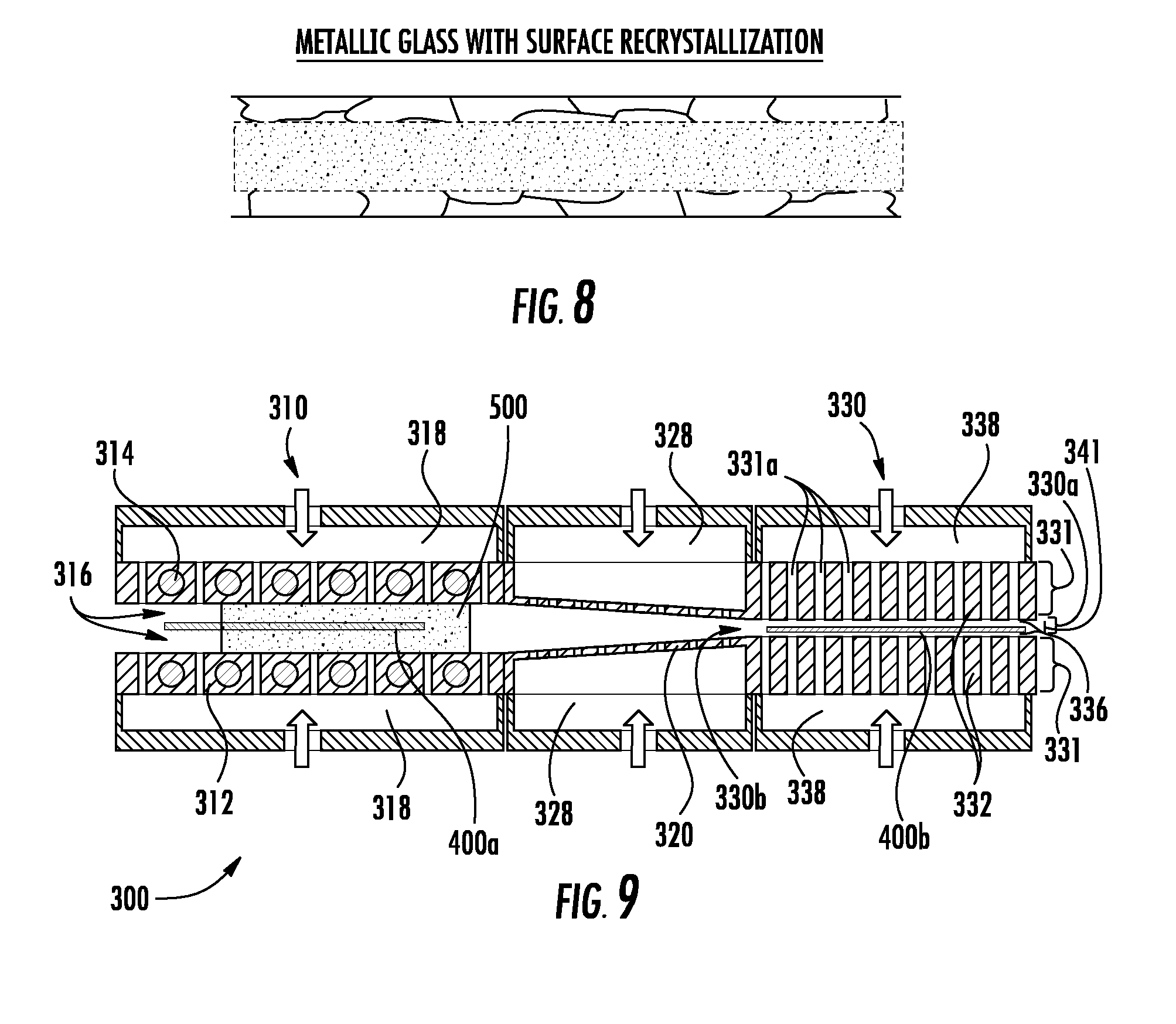
[0071] Referring now to FIG. 8, a representative microstructure of a metallic glass having been processed through the metal thermal treatment system 300 illustrates surface regions of the metallic glass thin sheet having been recrystallized while an inner region remains with an amorphous or glass morphology. Such thermal treatment provides an article with surfaces that are resistant to crack initiation and propagation and an interior with increased tensile strength and elastic strain limit.
[0072] Referring now to FIG. 9, in embodiments, the thermal treatment system 300 chemically alters surface regions of articles that pass therethrough. Particularly, a gaseous atmosphere 500 with one or more chemical elements (e.g. Cr, C, B, N, Al, Si, etc.) to be deposited onto the sheet 400a is shown. While FIG. 9 illustrates the gaseous atmosphere 500 on both sides of the sheet 400a, in embodiments, the thermal treatment system 300 can provide the gaseous atmosphere 500 primarily to only one side of the sheet 400a. Once the one or more chemical elements in the gaseous atmosphere 500 are deposited onto the surface of the sheet 400a, the one or more chemical elements can diffuse into surface regions of the sheet 400a and thereby alloy with the sheet 400a to provide a chemically altered surface. In the alternative, the one or more chemical elements deposited onto the surface of the sheet 400a can remain at the surface and thereby provide a chemically altered surface. The gaseous atmosphere 500 can be provided or generated using a chemical vapor deposition (CVD) process, a plasma deposition process, etc. In embodiments, the gaseous atmosphere 500 assists in supporting the sheet 400a such that the sheet 400a does not come into physical contact with the heat sources 314. The thermal treatment system 300 with the gaseous atmosphere 500 can chromize a surface region of the sheet 400a (chromizing), carburize a surface region of the sheet 400a (carburizing), boride a surface region of the sheet 400a (boriding), nitride a surface region of the sheet 400a (nitriding), aluminize a surface region of the sheet 400a (aluminizing), siliconize a surface region of the sheet 400a (siliconizing) and combinations thereof.
EXAMPLES
[0073] Apparatus setup--As detailed above, the apparatus comprises three zones--a hot zone, a transition zone, and a cold zone. The gaps between the top and bottom thermal bearings in the hot zone and cold zone are set to desired spacings. Gas flow rates in the hot zone, transition zone, and quench zone are set to ensure centering of the article on the gas-bearing. The hot zone can be pre-heated to a desired temperature T.sub.o where the article will be held a predetermined and desired amount of time before being transferred to the cold zone and cooled. The temperature T.sub.0 is determined by metallic material of the article being thermally treated and the specific thermal treatment being performed on the article. The time to equilibration is dependent at least on the thickness of the article. For example, for sheets of approximately 1.1 mm or less, equilibration occurs in approximately 10 seconds. For 3 mm sheets, equilibration occurs in approximately 10 seconds to 30 seconds. For thicker sheets, up to approximately 6 mm, the equilibration time may be on the order of 60 seconds. Once the article has equilibrated to T.sub.0, it can be held at T.sub.o for a desired amount of time and then transferred through the transition zone on gas bearings and into the cooling or quench zone. The article cools at a desired cooling rate to a temperature below T.sub.o (T.sub.L)and may or may not be held in the cold zone at T.sub.L for an extended period of time before exiting the cold zone. The article can be maintained in the cold zone for any period of time from 1 second, 10 seconds, 1 minute, several minutes, 1 hour, several hours or more, depending on the thermal treatment desired and/or the desired temperature of the article at removal.
[0074] A variety of different alloys can be thermally treated with the thermal treatment system disclosed herein. Examples of such alloys and microstructures and mechanical properties that can be obtained are provided.
Aluminum Alloys
Example 1
[0075] A 6061 wrought aluminum sheet having a chemical composition in weight percent of 0.15 Mn, 0.4-0.8 Si, 0.15-0.35 Cr, 0.15-0.4 Cu, 0.7 Fe, 0.25 Zn, 0.8-1.2 Mg, 0.15 Ti, with the remainder being Al and other incidental impurities was provided as thin sheet having a thickness of 1 mm. The thin sheet was annealed in the hot zone at 775.degree. F. for 2 hours followed by controlled cooling at 50.degree. F. per hour down to 500.degree. F., followed by air cooling. The material was subjected to an age hardening heat treatment at 350.degree. F. for 8 hours followed by air cooling in order to produce the T6 temper. Mechanical properties of the 6061 aluminum sheet with the T6 temper showed an average tensile strength of 45,000 psi, yield strength of 40,000 psi, shear strength of 31,000 psi, elongation to failure of 12%, and a Brinell hardness of 95.
Steel Alloys
Example 2
[0076] A cold rolled steel alloy sheet having a thickness of 0.5 mm and a chemical composition within the range and weight percent of 0.085-0.11 C, 1.4-2.0 Mn, 0.09-0.21 Mo, 0.02-0.05 Al, 0.16-0.5 Si, 0.13-0.5 Cr, 0.016 max Ti, 0.06 max Ni, 0.003 max S, 0.015 max P, 0.006 max N, and with the balance being iron and incidental metal impurities can be processed through the metal thermal treatment system 300 and subjected to an intercritical annealing in the hot zone at temperatures between 760-800.degree. C. Thereafter, the intercritically annealed steel alloy sheet can be rapidly cooled to a temperature of less than 450.degree. C. in the cold zone. The rapidly cooled sheet has a ferrite-martensite microstructure with less than 6 volume percent bainite, a 0.2% yield strength of at least 330 MPa, a tensile strength of at least 590 MPa, a total elongation to failure of at least 18%, and a uniform elongation of at least 10%.
Cobalt and Nickel Solid-Solution-Strengthened Alloys
[0077] Although Co-base and Ni-base solid-solution strengthened alloys employ second phase precipitates such as Cr-carbides, W-carbides, etc., to assist in high temperature strengthening of the material, the primary strengthening mechanism can be the addition and alloying of various elements within the Co or Ni matrix to provide "solid solution strengthening."
Example 3
[0078] One Co-base and two Ni-base solid-solution strengthened alloys having the following nominal chemical compositions (wt %) can be processed through the metal thermal treatment system 300.
[0079] Cobalt Alloy (C1): 10 Ni, 20 Cr, 15 W, 3 max Fe 1.5 Mn, 0.4 max Si, 0.10 C with the balance Co (approximately 51 et %) and incidental impurities (commercially available as HAYNES.RTM. 25 alloy).
[0080] First Nickel Alloy (N1): 22 Cr, 14 W, 2 Mo, 3 max Fe, 5 max Co, 0.5 Mn, 0.4 Si, 0.3 Al, 0.10 C, 0.02 La, 0.015 max B, with the balance Ni (approximately 57 wt %) and incidental impurities (commercially available as HAYNES.RTM. 230.RTM. alloy).
[0081] Second Nickel Alloy (N2): 22 Cr 18 Fe 9 Mo 1.5 Co 0.6 W 0.10 C 1 max Mn 1 max Si 0.008 B with the balance Ni (approximately 47 wt %) and incidental impurities (commercially available as HAYNES.RTM. Hastelloy.RTM. X alloy).
[0082] Typical solution annealing temperatures provided by the thermal treatment system 300 for the C1 and N1-N2 alloys are shown in Table 1 below. Such solid-solution-strengthened alloys are typically supplied in the solution annealed condition with microstructures of primary carbides dispersed in a single phase matrix. The microstructure can be free of primary carbides at grain boundaries and provides an optimum combination for room temperature fabricability and elevated temperature properties once the material can be put into service. Heat treatments performed at temperatures below the solution heat treating temperature range provided by the thermal treatment system 300 are known as mill annealing or stress relief thermal treatments (see Table 1 below). Mill annealing treatments are employed for restoring formed, partially fabricated, or otherwise as-worked alloy material to a condition where additional deformation or welding of the material can be performed. Such treatments may also be used to produce structures in finished raw materials which are optimum for specific forming operations. For example, mill annealing thermal treatments provided by the thermal treatment system 300 can be used to produce a microstructure with a fine grain size for deep drawing applications. Mill annealing of the solid-solution-strengthened alloys by the thermal treatment system 300 can also be used to relief stress and yet avoid article distortion that can occur at full solution annealing temperatures. However, it should be appreciated that the gas bearings of the thermal treatment system 300 support the solid-solution-strengthened alloys during annealing and thus can actually impose and ensure a final shape is maintained during the higher temperature solution annealing thermal treatments. Use of a mill annealing heat treatment typically results in precipitation of secondary carbides on grain boundaries of material originally supplied in the solution-annealed condition, and will not normally restore the material to the as-received condition.
TABLE-US-00001 TABLE 1 Typical Solution Annealing Minimum Mill Annealing Temperatures (.degree. C.) Temperature (.degree. C.) Co alloy 1175-1230 1120 Fe-base alloy 1165-1190 1035 Ni1 alloy 1165-1245 1120 Ni2 alloy 1165-1190 1010
[0083] When the solid-solution-strengthened are in the cold or warm-worked condition, i.e. after cold working of the material, application of a mill anneal or solution heat thermal treatment by the thermal treatment system 300 typically alters the microstructure of the article. The amount of prior cold work in the article influences the resulting microstructure and mechanical properties of the article. The results for several combinations of prior cold work and annealing temperature upon the microstructure response for sheet of the alloys noted above are shown below in Table 2.
TABLE-US-00002 TABLE 2 Amount Anneal Resulting ASTM Grain Size** of Cold Temperature* Co Fe Ni1 Ni2 Work % (.degree. C.) alloy alloy alloy alloy 0 None 31/2-4 5-6 5-6 4-5 10 1010 N/A NR N/A NR 1065 NR NR NR NR 1120 NR 5-51/2 NFR 5-7 1175 4-41/2 5-51/2 4-7 N/A 1230 3-41/2 N/A 61/2-7 N/A 15 1065 7 N/A N/A N/A 1120 6-7 N/A N/A N/A 1175 5-7 N/A N/A N/A 1230 3-41/2 N/A N/A N/A 20 1010 N/A NR N/A NFR 1065 7-8 NR NFR NFR 1120 7-8 71/2-81/2 8-81/2 7-8 1175 41/2-7 6-61/2 71/2-8 N/A 1230 21/2-41/2 N/A 7-71/2 N/A 25 1065 71/2-8 N/A N/A N/A 1120 71/2-8 N/A N/A N/A 1175 4 N/A N/A N/A 1230 31/2 N/A N/A N/A 30 1010 N/A NFR N/A NFR 1065 N/A 71/2-91/2 8-9 8-10 1120 N/A 7-71/2 9-10 71/2-91/2 1175 N/A 41/2-61/2 81/2-9 N/A 1230 N/A N/A 6-7 N/A 40 1010 N/A 71/2-91/2 N/A 8-9 1065 N/A 8-91/2 91/2-10 8-10 1120 N/A 7-9 9-10 91/2-10 1175 N/A 41/2-61/2 81/2-9 N/A 1230 N/A N/A 4-7 N/A 50 1010 N/A 9-10 N/A 81/2-10 1065 N/A 81/2-10 9-10 81/2-10 1120 N/A 8-91/2 9-10 81/2-10 1175 N/A 51/2-6 9-91/2 N/A 1230 N/A N/A 51/2-61/2 N/A
[0084] Currently available commercial annealing furnaces for such alloys have temperature tolerances of +/-15.degree. C. with tolerances of +/-10.degree. C. obtainable with specialized equipment. However with the very small gap between the heat sources and the metallic material article in the thermal treatment system 300, temperature tolerances can be maintained within +/-8.degree. C., and, in some embodiments, between +/-6.degree. C., +/-4.degree. C., +/-3.degree. C., +/-2.degree. C., or +/-1.degree. C. at annealing temperatures up to 1200.degree. C. Accordingly, greater temperature control provides increased microstructure and mechanical property control of articles thermally treated with embodiments of the thermal treatment system disclosed herein.
Nickel Age-Hardenable Alloys
Example 4
[0085] Two Ni-base age-hardenable (also known as precipitation hardenable or precipitation strengthenable) alloys having the following nominal chemical compositions (wt %) can be processed through the metal thermal treatment system 300.
[0086] First Ni-base age-hardenable alloy (NiAH1): 13.5 Co, 2 max Fe, 19 Cr, 4.3 Mo, 1.5 Al, 3 Ti, 0.08 C, 0.1 max Mn, 0.15 max Si, 0.006 B, 0.1 Cu, 0.05 Zr, with balance Ni (approximately 58 wt %) and incidental impurities (commercially available as HAYNES.RTM. Waspaloy alloy).
[0087] Second Ni-base age-hardenable alloy (NiAH2): 16 Cr, 8 Fe, 2.5 Ti, 1 Nb, 0.8 Al, 1 max Co, 0.35 max Mn, 0.35 max Sai, 0.08 max C, with balance Ni (approximately 70 wt %) and incidental impurities (commercially available as INCONEL.RTM. X-750 alloy and HAYNES.RTM. X-750 alloy).
[0088] Ni-base age-hardenable alloys derive most of their strength from thermal treatments that result in a range of second phase precipitates in the microstructure. The predominant precipitate is Ni.sub.3Al (gamma prime). Thermal treatment of such alloys to provide the precipitation hardened microstructure requires a number of heating and cooling steps. For example, a typical heat treatment for the NiAH1 alloy to provide the precipitation hardened microstructure includes solution annealing the material at 1080.degree. C. for 30 minutes followed by a water quench. Then the material is subjected to a first precipitation thermal treatment at 995.degree. C. for 2 hours followed by air cooling to room temperature, then a second precipitation thermal treatment at 845.degree. C. for 4 hours followed by air cooling to room temperature, and then a third precipitation thermal treatment at 760.degree. C. for 16 hours followed air cooling to room temperature. The resulting precipitation hardened microstructure for the NiAH1 provides excellent mechanical properties up to temperatures approximately 700.degree. C. as shown in Table 3 (tensile test properties) and Table 4 (stress-rupture properties) below.
TABLE-US-00003 TABLE 3 Ultimate Test Tensile Strength 0.2% Yield Elongation in Temperature (.degree. C.) (MPa) Strength (MPa) 51 mm (%) ROOM 1335 910 26.6 650 1195 770 20.8 760 970 770 12.0 870 545 415 12.0 980 220 135 19.4 1095 83 41 36.8
TABLE-US-00004 TABLE 4 Approximate Initial Stress in Test Temperature MPa to Produce Rupture in: (.degree. C.) 10 Hours 100 Hours 1000 Hours 600 -- -- 660 650 -- 635 550 705 615 515 395 760 495 365 240 815 345 220 130 870 215 125 68 925 120 66 --
[0089] For another example, a typical heat treatment for the NiAH2 alloy to provide the precipitation hardened microstructure includes solution annealing the material at 1040.degree. C. followed by a first precipitation thermal treatment at 730.degree. C. for 8 hours followed by furnace cooling to a second precipitation thermal treatment at 620.degree. C. for 8 hours followed by air cooling to room temperature. The resulting precipitation hardened microstructure for the NiAH2 provides excellent mechanical properties up to temperatures approximately 700.degree. C. as shown in Tables 5 and 6 below.
TABLE-US-00005 TABLE 5 Ultimate Test Tensile Strength 0.2% Yield Elongation in Temperature (.degree. C.) (MPa) Strength (MPa) 51 mm (%) ROOM 1325 975 23.6 540 1120 860 22.2 650 990 835 5.8 760 650 635 2.5 870 360 295 8.0 980 115 63 42.0
TABLE-US-00006 TABLE 6 Approximate Initial Stress in Test Temperature MPa to Produce Rupture in: (.degree. C.) 10 Hours 100 Hours 1000 Hours 600 825 585 490 650 550 455 345 705 420 310 200 760 285 180 105 815 165 97 51 870 86 46 -- 925 45 -- --
[0090] Other aspects and advantages will be apparent from a review of the specification as a whole, the appended claims and Appendix A.
[0091] The construction and arrangements of the metallic materials as shown in the various exemplary embodiments, are illustrative only. Although only a few embodiments have been described in detail in this disclosure, many modifications are possible (e.g., variations in sizes, dimensions, structures, shapes, and proportions of the various elements, values of parameters, mounting arrangements, use of materials, orientations) without materially departing from the novel teachings and advantages of the subject matter described herein. Some elements shown as integrally formed may be constructed of multiple parts or elements, the position of elements may be reversed or otherwise varied, and the nature or number of discrete elements or positions may be altered or varied. The order or sequence of any process, logical algorithm, or method steps may be varied or re-sequenced according to alternative embodiments. Other substitutions, modifications, changes and omissions may also be made in the design, operating conditions and arrangement of the various exemplary embodiments without departing from the scope of the present inventive technology.
* * * * *
D00000
D00001
D00002
D00003
XML
uspto.report is an independent third-party trademark research tool that is not affiliated, endorsed, or sponsored by the United States Patent and Trademark Office (USPTO) or any other governmental organization. The information provided by uspto.report is based on publicly available data at the time of writing and is intended for informational purposes only.
While we strive to provide accurate and up-to-date information, we do not guarantee the accuracy, completeness, reliability, or suitability of the information displayed on this site. The use of this site is at your own risk. Any reliance you place on such information is therefore strictly at your own risk.
All official trademark data, including owner information, should be verified by visiting the official USPTO website at www.uspto.gov. This site is not intended to replace professional legal advice and should not be used as a substitute for consulting with a legal professional who is knowledgeable about trademark law.