Vehicular Adaptive Headlighting System
Higgins-Luthman; Michael J. ; et al.
U.S. patent application number 16/147948 was filed with the patent office on 2019-02-07 for vehicular adaptive headlighting system. The applicant listed for this patent is MAGNA ELECTRONICS INC.. Invention is credited to Michael J. Higgins-Luthman, William C. Ince, Yuesheng Lu.
| Application Number | 20190039507 16/147948 |
| Document ID | / |
| Family ID | 40252940 |
| Filed Date | 2019-02-07 |


| United States Patent Application | 20190039507 |
| Kind Code | A1 |
| Higgins-Luthman; Michael J. ; et al. | February 7, 2019 |
VEHICULAR ADAPTIVE HEADLIGHTING SYSTEM
Abstract
A vehicular adaptive driving beam headlighting system includes a camera disposed at and viewing forwardly through a windshield of a vehicle. A control includes an image processor that processes image data captured by the camera at night to detect headlights present in a field of view of the camera of an oncoming vehicle that is approaching the equipped vehicle along a traffic lane to the left of a traffic lane of a road that the equipped vehicle is travelling along. A left-side headlamp is disposed at a left-side front portion of the equipped vehicle and a right-side headlamp is disposed at a right-side front portion of the equipped vehicle. Responsive to detection of headlights of an oncoming vehicle, the left-side headlamp beam of light is adjusted to reduce glaring a driver of the oncoming vehicle.
| Inventors: | Higgins-Luthman; Michael J.; (Livonia, MI) ; Lu; Yuesheng; (Farmington Hills, MI) ; Ince; William C.; (Novi, MI) | ||||||||||
| Applicant: |
|
||||||||||
|---|---|---|---|---|---|---|---|---|---|---|---|
| Family ID: | 40252940 | ||||||||||
| Appl. No.: | 16/147948 | ||||||||||
| Filed: | October 1, 2018 |
Related U.S. Patent Documents
| Application Number | Filing Date | Patent Number | ||
|---|---|---|---|---|
| 14467297 | Aug 25, 2014 | 10086747 | ||
| 16147948 | ||||
| 13427166 | Mar 22, 2012 | 8814401 | ||
| 14467297 | ||||
| 13292120 | Nov 9, 2011 | 8142059 | ||
| 13427166 | ||||
| 13074698 | Mar 29, 2011 | 8070332 | ||
| 13292120 | ||||
| 12171436 | Jul 11, 2008 | 7914187 | ||
| 13074698 | ||||
| 60949352 | Jul 12, 2007 | |||
| Current U.S. Class: | 1/1 |
| Current CPC Class: | B60Q 2300/23 20130101; B60Q 1/245 20130101; B60Q 2300/45 20130101; B60Q 1/085 20130101 |
| International Class: | B60Q 1/08 20060101 B60Q001/08; B60Q 1/24 20060101 B60Q001/24 |
Claims
1. A vehicular adaptive driving beam headlighting system, said vehicular adaptive driving beam headlighting system comprising: a camera disposed at and viewing forwardly through a windshield of a vehicle equipped with said vehicular adaptive driving beam headlighting system; wherein said camera comprises a plurality of CMOS photosensors arranged in a two dimensional array; wherein said camera is operable to capture image data; a control comprising an image processor; wherein said image processor processes image data captured by said camera at night to detect headlights present in a field of view of said camera of an oncoming vehicle that is approaching the equipped vehicle along a traffic lane to the left of a traffic lane of a road that the equipped vehicle is travelling along; a left-side headlamp disposed at a left-side front portion of the equipped vehicle, said left-side headlamp comprising a left-side illumination source that emits a left-side headlamp beam of light to illuminate forwardly of the equipped vehicle and sidewardly to the left of the equipped vehicle, said left-side illumination source comprising a plurality of light emitting diodes; a right-side headlamp disposed at a right-side front portion of the equipped vehicle, said right-side headlamp comprising a right-side illumination source that emits a right-side headlamp beam of light to illuminate forwardly of the equipped vehicle and sidewardly to the right of the equipped vehicle, said right-side illumination source comprising a plurality of light emitting diodes; wherein, responsive to detection via image processing by said image processor of captured image data of headlights of an oncoming vehicle that is travelling along the traffic lane to the left of the traffic lane that the equipped vehicle is travelling along, the left-side headlamp beam of light emitted by said left-side headlamp is adjusted to reduce glaring a driver of the oncoming vehicle; wherein said adjustment of the left-side headlamp beam is independent of any adjustment of the right-side headlamp beam of light emitted by said right-side headlamp; and wherein said adjustment of the left-side headlamp beam comprises selectively activating at least some individual light emitting diodes of said plurality of light emitting diodes of said left-side illumination source.
2. The vehicular adaptive driving beam headlighting system of claim 1, wherein, responsive to detection via image processing by said image processor of captured image data of a pedestrian present at or near the right side edge of the road that the equipped vehicle is travelling along that is to the right of the traffic lane that the equipped vehicle is travelling along, the right-side headlamp beam of light emitted by said right-side headlamp is adjusted to illuminate the detected pedestrian, and wherein said adjustment of the right-side headlamp beam is independent of any adjustment of the left-side headlamp beam of light emitted by said left-side headlamp, and wherein said adjustment of the right-side headlamp beam comprises selectively activating at least some individual light emitting diodes of said plurality of light emitting diodes of said right-side illumination source.
3. The vehicular adaptive driving beam headlighting system of claim 2, wherein the right-side headlamp beam emitted by said right-side headlamp is adjusted at least in part responsive to one selected from the group consisting of (a) distance from the equipped vehicle to the detected pedestrian and (b) direction from the equipped vehicle toward the detected pedestrian.
4. The vehicular adaptive driving beam headlighting system of claim 2, wherein adjustment of the right-side headlamp beam comprises activating some light emitting diodes of said plurality of light emitting diodes of said right-side illumination source to aim a portion of the right-side headlamp beam towards the detected pedestrian and activating other light emitting diodes of said plurality of light emitting diodes of said right-side illumination source to aim another portion of the right-side headlamp beam in a different direction.
5. The vehicular adaptive driving beam headlighting system of claim 4, wherein said plurality of light emitting diodes of said right-side illumination source comprises an array of light emitting diodes.
6. The vehicular adaptive driving beam headlighting system of claim 5, wherein the right-side light beam of said right-side headlamp is adjustable horizontally.
7. The vehicular adaptive driving beam headlighting system of claim 6, wherein the right-side light beam of said right-side headlamp is adjustable vertically.
8. The vehicular adaptive driving beam headlighting system of claim 6, wherein, responsive to said pedestrian detection, said control generates an alert to a driver of the equipped vehicle seated at a left side of the equipped vehicle, and wherein said alert comprises at least one alert selected from the group consisting of (a) a visual display, (b) a warning light, (c) an audible signal and (d) a haptic alert.
9. The vehicular adaptive driving beam headlighting system of claim 1, wherein said vehicular adaptive driving beam headlighting system is enabled in response to an output of at least one selected from the group consisting of (a) a human-machine interface, (b) a Global Positioning System, (c) a roadside information system, (d) the internet, (e) an intelligent transportation system, (f) a communication system, (g) a telematics system and (h) a navigation system.
10. The vehicular adaptive driving beam headlighting system of claim 1, comprising a gaze detection device operable to determine a gaze direction of a driver of the equipped vehicle seated at a left side of the equipped vehicle, wherein said gaze detection device comprises a second camera for capturing image data, said second camera having a field of view toward the head of the driver of the equipped vehicle, and wherein an image processing device processes image data captured by said second camera to determine the gaze direction of the driver of the equipped vehicle.
11. The vehicular adaptive driving beam headlighting system of claim 10, wherein the right-side headlamp beam emitted by said right-side headlamp is adjusted at least in part responsive to a determination by said gaze detection device of the gaze direction of the driver of the equipped vehicle seated at the left side of the equipped vehicle.
12. The vehicular adaptive driving beam headlighting system of claim 1, wherein, responsive to detection via image processing by said image processor of captured image data of a sign ahead of the equipped vehicle that is present at a road side edge of the road that the equipped vehicle is travelling along that is to the right of the traffic lane that the equipped vehicle is travelling along, the right-side headlamp beam of light emitted by said right-side headlamp is adjusted to illuminate the detected sign, and wherein said adjustment of the right-side headlamp beam is independent of any adjustment of the left-side headlamp beam of light emitted by said left-side headlamp, and wherein said adjustment of the right-side headlamp beam comprises selectively activating at least some individual light emitting diodes of said plurality of light emitting diodes of said right-side illumination source.
13. The vehicular adaptive driving beam headlighting system of claim 12, wherein the right-side headlamp beam emitted by said right-side headlamp is adjusted at least in part responsive to one selected from the group consisting of (a) distance from the equipped vehicle to the detected sign and (b) direction from the equipped vehicle toward the detected sign.
14. The vehicular adaptive driving beam headlighting system of claim 12, wherein adjustment of the right-side headlamp beam comprises activating at least some light emitting diodes of said plurality of light emitting diodes of said right-side illumination source to aim a portion of the right-side headlamp beam towards the detected sign and activating other light emitting diodes of said plurality of light emitting diodes of said right-side illumination source to aim another portion of the right-side headlamp beam in a different direction.
15. The vehicular adaptive driving beam headlighting system of claim 14, wherein the at least some light emitting diodes of said plurality of light emitting diodes of said right-side illumination source activated to aim the portion of the right-side headlamp beam towards the detected sign comprise near-infrared light emitting diodes.
16. A vehicular adaptive driving beam headlighting system, said vehicular adaptive driving beam headlighting system comprising: a camera disposed at and viewing forwardly through a windshield of a vehicle equipped with said vehicular adaptive driving beam headlighting system; wherein said camera comprises a plurality of CMOS photosensors arranged in a two dimensional array; wherein said camera is operable to capture image data; a control comprising an image processor; wherein said image processor processes image data captured by said camera at night to detect headlights present in a field of view of said camera of an oncoming vehicle that is approaching the equipped vehicle along a traffic lane to the left of a traffic lane of a road that the equipped vehicle is travelling along; a left-side headlamp disposed at a left-side front portion of the equipped vehicle, said left-side headlamp comprising a left-side illumination source that emits a left-side headlamp beam of light to illuminate forwardly of the equipped vehicle and sidewardly to the left of the equipped vehicle, said left-side illumination source comprising a plurality of light emitting diodes; a right-side headlamp disposed at a right-side front portion of the equipped vehicle, said right-side headlamp comprising a right-side illumination source that emits a right-side headlamp beam of light to illuminate forwardly of the equipped vehicle and sidewardly to the right of the equipped vehicle, said right-side illumination source comprising a plurality of light emitting diodes; wherein, responsive to detection via image processing by said image processor of captured image data of headlights of an oncoming vehicle that is travelling along the traffic lane to the left of the traffic lane that the equipped vehicle is travelling along, the left-side headlamp beam of light emitted by said left-side headlamp is adjusted to reduce glaring a driver of the oncoming vehicle; wherein said adjustment of the left-side headlamp beam is independent of any adjustment of the right-side headlamp beam of light emitted by said right-side headlamp; wherein said adjustment of the left-side headlamp beam comprises selectively activating at least some individual light emitting diodes of said plurality of light emitting diodes of said left-side illumination source; wherein, responsive to detection via image processing by said image processor of captured image data of an object of interest present at or near the right side edge of the road that the equipped vehicle is travelling along that is to the right of the traffic lane that the equipped vehicle is travelling along, the right-side headlamp beam of light emitted by said right-side headlamp is adjusted to illuminate the detected object of interest; wherein said adjustment of the right-side headlamp beam is independent of any adjustment of the left-side headlamp beam of light emitted by said left-side headlamp; and wherein said adjustment of the right-side headlamp beam comprises selectively activating at least some individual light emitting diodes of said plurality of light emitting diodes of said right-side illumination source to provide a localized beam of light that is directed toward the detected object of interest at or near the right side edge of the road.
17. The vehicular adaptive driving beam headlighting system of claim 16, wherein the detected object of interest comprises a pedestrian.
18. The vehicular adaptive driving beam headlighting system of claim 16, wherein the detected object of interest comprises a sign.
19. The vehicular adaptive driving beam headlighting system of claim 16, wherein the detected object of interest comprises an animal.
20. The vehicular adaptive driving beam headlighting system of claim 16, wherein adjustment of the right-side headlamp beam to provide the localized beam of light that is directed toward the detected object of interest is responsive, at least in part, to a steering angle of the equipped vehicle.
21. A vehicular adaptive driving beam headlighting system, said vehicular adaptive driving beam headlighting system comprising: a camera disposed at and viewing forwardly through a windshield of a vehicle equipped with said vehicular adaptive driving beam headlighting system; wherein said camera comprises a plurality of CMOS photosensors arranged in a two dimensional array; wherein said camera is operable to capture image data; a control comprising an image processor; wherein said image processor processes image data captured by said camera at night to detect headlights present in a field of view of said camera of an oncoming vehicle that is approaching the equipped vehicle along a traffic lane to the left of a traffic lane of a road that the equipped vehicle is travelling along; a left-side headlamp disposed at a left-side front portion of the equipped vehicle, said left-side headlamp comprising a left-side illumination source that emits a left-side headlamp beam of light to illuminate forwardly of the equipped vehicle and sidewardly to the left of the equipped vehicle, said left-side illumination source comprising a plurality of light emitting diodes; a right-side headlamp disposed at a right-side front portion of the equipped vehicle, said right-side headlamp comprising a right-side illumination source that emits a right-side headlamp beam of light to illuminate forwardly of the equipped vehicle and sidewardly to the right of the equipped vehicle, said right-side illumination source comprising a plurality of light emitting diodes; wherein, responsive to detection via image processing by said image processor of captured image data of headlights of an oncoming vehicle that is travelling along the traffic lane to the left of the traffic lane that the equipped vehicle is travelling along, the left-side headlamp beam of light emitted by said left-side headlamp is adjusted independent of any adjustment of the right-side headlamp beam of light emitted by said right-side headlamp; wherein said adjustment of the left-side headlamp beam comprises selectively activating at least some individual light emitting diodes of said plurality of light emitting diodes of said left-side illumination source; wherein, responsive to detection via image processing by said image processor of captured image data of an object of interest present at or near the right side edge of the road that the equipped vehicle is travelling along that is to the right of the traffic lane that the equipped vehicle is travelling along, the right-side headlamp beam of light emitted by said right-side headlamp is adjusted to illuminate the detected object of interest; wherein the detected object of interest comprises an object selected from the group consisting of (i) a pedestrian, (ii) a sign and (iii) an animal; wherein said adjustment of the right-side headlamp beam is independent of any adjustment of the left-side headlamp beam of light emitted by said left-side headlamp; and wherein said adjustment of the right-side headlamp beam comprises selectively activating at least some individual light emitting diodes of said plurality of light emitting diodes of said right-side illumination source to provide a localized beam of light that is directed toward the detected object of interest at or near the right side edge of the road.
22. The vehicular adaptive driving beam headlighting system of claim 21, wherein the localized beam of light that is directed toward the detected object of interest is adjustable horizontally.
23. The vehicular adaptive driving beam headlighting system of claim 22, wherein the localized beam of light that is directed toward the detected object of interest is adjustable vertically.
24. The vehicular adaptive driving beam headlighting system of claim 21, wherein, responsive to said detection of the detected object of interest, said control generates an alert to a driver of the equipped vehicle seated at the left side of the equipped vehicle, and wherein said alert comprises at least one alert selected from the group consisting of (a) a visual display, (b) a warning light, (c) an audible signal and (d) a haptic alert.
25. The vehicular adaptive driving beam headlighting system of claim 21, wherein the at least some light emitting diodes of said plurality of light emitting diodes of said right-side illumination source activated to provide the localized beam of light that is directed toward the detected object of interest comprise near-infrared light emitting diodes.
26. The vehicular adaptive driving beam headlighting system of claim 21, wherein, responsive to detection via image processing by said image processor of captured image data of headlights of the oncoming vehicle that is travelling along the traffic lane to the left of the traffic lane that the equipped vehicle is travelling along, the left-side headlamp beam of light emitted by said left-side headlamp is adjusted to reduce glaring a driver of the oncoming vehicle, and wherein said adjustment of the left-side headlamp beam is independent of any adjustment of the right-side headlamp beam of light emitted by said right-side headlamp.
Description
CROSS REFERENCE TO RELATED APPLICATIONS
[0001] The present application is a continuation of U.S. patent application Ser. No. 14/467,297, filed Aug. 25, 2014, now U.S. Pat. No. 10,086,747, which is a continuation of U.S. patent application Ser. No. 13/427,166, filed Mar. 22, 2012, now U.S. Pat. No. 8,814,401, which is a continuation of U.S. patent application Ser. No. 13/292,120, filed Nov. 9, 2011, now U.S. Pat. No. 8,142,059, which is a continuation of U.S. patent application Ser. No. 13/074,698, filed Mar. 29, 2011, now U.S. Pat. No. 8,070,332, which is a continuation of U.S. patent application Ser. No. 12/171,436, filed Jul. 11, 2008, now U.S. Pat. No. 7,914,187, which claims the benefit of U.S. provisional application Ser. No. 60/949,352, filed Jul. 12, 2007, which are hereby incorporated herein by reference in their entireties.
FIELD OF THE INVENTION
[0002] The present invention relates generally to vehicle lighting systems and, more particularly, to vehicle lighting systems that may control the headlamps of the vehicle.
BACKGROUND OF THE INVENTION
[0003] Vehicle vision systems and/or vehicle headlamp control systems are known and provide enhanced automatic control of the headlamps of a vehicle, typically in response to a detection of a threshold ambient light level and/or a detection of light (such as headlamps of oncoming vehicles and/or taillights of leading vehicles) in the region forward of the vehicle. Examples of such vision and/or headlamp control systems are described in U.S. Pat. Nos. 5,550,677; 5,877,897; 6,498,620; 5,670,935; 5,796,094; 6,396,397; 6,806,452; 6,690,268; 7,005,974; 7,123,168; 7,004,606; 6,946,978; 7,038,577; 6,353,392; 6,320,176; 6,313,454 and 6,824,281, which are all hereby incorporated herein by reference in their entireties.
SUMMARY OF THE INVENTION
[0004] The present invention provides an automatic vehicle lighting system or light control system with an adaptive alignment function. The light control system of the present invention is operable to control or adjust the beam of a light of the vehicle (or of the headlamps or auxiliary light of the vehicle) in response to a detection of a gaze direction or head angle or pose or position of the head or eyes of the driver of the vehicle, so as to provide enhanced illumination in the direction that the driver is looking, such as toward road signs and/or the like along the road on which the vehicle is traveling.
[0005] Optionally, the light control system may be responsive to a detection of a gaze direction of a driving instructor (typically seated in the front passenger seat of the vehicle during a driving instruction or test for the person or student driving the vehicle). In such an application, the light control system provides the driving instructor with a tool to direct the attention of the student in a way that does not force the driver or student to look at the hand-pointing of the instructor, but at the relevant object which is illuminated or highlighted by the automatic adaptively-aligned lighting system.
[0006] According to an aspect of the present invention, an automatic lighting system for a vehicle includes a gaze detection device operable to determine a gaze direction of a driver or driving instructor or front seat occupant of a vehicle, an illumination source and a control. The illumination source is directed generally forwardly with respect to a direction of travel of the vehicle, and has an adjustable principal axis of illumination. The control is operable to adjust the principal axis of illumination of the illumination source in response to an output of the gaze detection device. The control adjusts the principal axis of illumination of the illumination source to direct illumination toward an area where the driver or driving instructor or front seat occupant of the vehicle is looking.
[0007] Optionally, the gaze detection device may comprise an imaging device for capturing images, with the imaging device having a field of view directed generally toward the head of a driver or driving instructor of the vehicle. An image processing device may process image data to determine the gaze direction of the driver or driving instructor of the vehicle. Optionally, the automatic lighting system may be selectively enabled and disabled in response to a human-machine interface or other systems or inputs. For example, such other systems may include an intelligent headlight system that detects other vehicles so that the host vehicle's light does not shine at the eyes of the driver of an oncoming or leading vehicle, a Global Positioning System (GPS), a roadside information system, the internet, an intelligent transportation system or information system, a communication system, a telematics system, a navigation system or the like, that may provide or generate an output, whereby the automatic illumination system may control the adjusting or enabling of the adaptive alignment light in response to such an output. For example, some geographical locations or jurisdictions may forbid or limit such adaptively aligned lighted systems, whereby it is envisioned that the automatic lighting system may override the adaptive alignment control or otherwise not adjust or limit the adjustment of the adaptive light when the vehicle is in such locations or jurisdictions (such as in response to an output of a global positioning system that is indicative of the vehicle being located at or in such a location or jurisdiction).
[0008] According to another aspect of the present invention, an automatic lighting system for a vehicle includes an imaging device for capturing images, a control and an illumination source directed generally forwardly with respect to the direction of travel of the vehicle. The imaging device has a field of view directed generally forwardly with respect to a direction of travel of the vehicle. The control is operable to process image data to determine if a sign, or other important object or object of interest (such as an object of interest to the driver or student or instructor), such as a deer or pedestrian or the like, is present generally forwardly and sidewardly of the vehicle as the vehicle travels along a road. The control is operable to adjust the illumination source in response to a detection of an object of interest (such as a sign or person or animal or other object) generally forwardly and sidewardly of the vehicle, with the control adjusting the illumination source to direct illumination toward an area encompassing the detected object of interest when the object of interest is detected.
[0009] These and other objects, advantages, purposes and features of the present invention will become more apparent upon review of the following specification in conjunction with the drawings.
BRIEF DESCRIPTION OF THE DRAWINGS
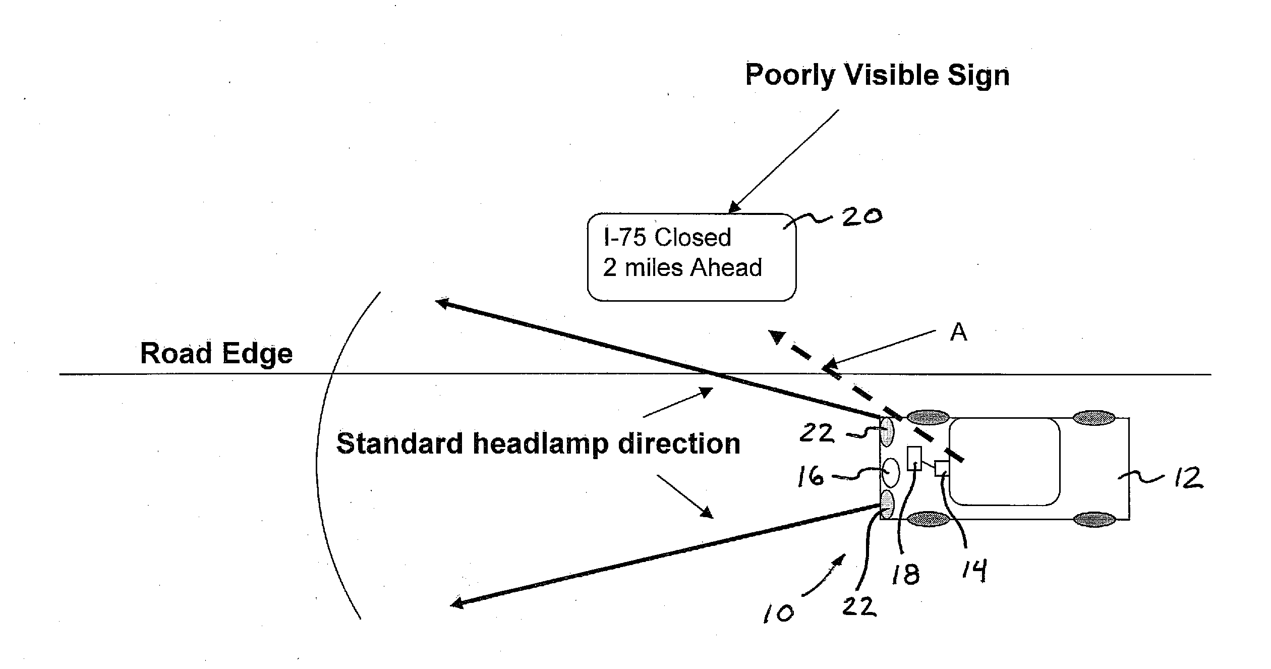
[0010] FIG. 1 is a schematic of a vehicle and lighting system, showing that the vehicle headlamps may not substantially illuminate a sign at the side of the road as the vehicle travels along the road and approaches and passes the sign;
[0011] FIG. 2 is a schematic of a vehicle and lighting system in accordance with the present invention, showing an adjustment of illumination from an illumination source to provide enhanced illumination of a sign in response to the driver's or driving instructor's gaze direction or head direction being angled or directed generally toward the sign; and
[0012] FIG. 3 is another schematic of another vehicle and lighting system in accordance with the present invention, showing that the principal axis of illumination from the illumination source may be adjusted to account for the offset of the illumination source from the driver or driving instructor.
DESCRIPTION OF THE PREFERRED EMBODIMENTS
[0013] Referring now to the drawings and the illustrative embodiments depicted therein, an automatic lighting system or miner's lighting system 10 of a vehicle 12 includes a gaze detection device 14, such as an imaging device or the like, that is operable to determine a gaze direction or head angle or pose or position of the head or eyes of the driver or driving instructor or occupant of the vehicle, and an illumination source 16 or "miner's light" that is operable or adjustable to provide illumination generally in the direction of the detected gaze or head angle A, so as to provide enhanced illumination of an area that the driver or driving instructor of the vehicle is looking toward (FIGS. 1 and 2). A control or image processor 18 may process the image data to determine the gaze direction or line of sight A and may adjust the angled illumination source accordingly. For example, the illumination source 16 may provide a centrally located illumination source or light or light emitting diode(s) (LED) or the like at a forward portion of the vehicle, and the illumination source may be pivotable or adjustable to adjust its principal axis of illumination toward either side of the vehicle and generally forwardly of the vehicle (and optionally vertically), so as to provide enhanced illumination of a sign or object 20 or the like located forwardly of the vehicle 12 and toward the side of the vehicle as the vehicle travels along a road surface.
[0014] The gaze detection device 14 may comprise an imaging sensor or device, such as a pixelated imaging array having a plurality of photosensors arranged in a two dimensional array on a semiconductor substrate, such as a CMOS imaging array or the like. The imaging array may be located within the vehicle, such as in an interior rearview mirror of the vehicle or an accessory module of the vehicle or an overhead console of the vehicle, or steering wheel column of the vehicle or instrument panel of the vehicle or the like, with its field of view directed generally toward a region of the interior cabin of the vehicle that is occupied by or encompasses a head of a typical or average sized driver of the vehicle (at the driver's seat of the vehicle) or driving instructor of the vehicle (typically at the front passenger seat of the vehicle). Optionally, other gaze detecting devices may be implemented while remaining in the spirit and scope of the present invention. The control or image processor processes the image data captured by the imaging device (such as via any suitable processing means, such as via edge detection algorithms or biometric characteristic recognition/identification algorithms or the like) to determine the direction of the driver's or driving instructor's gaze, and adjusts or activates the illumination source in response thereto.
[0015] Optionally, the gaze detection device may comprise a cellular telephone with a camera or imaging sensor incorporated therein (or other personal camera device). For example, a camera telephone may be mounted or docked at the vehicle dashboard or interior mirror or elsewhere in the vehicle cabin with the camera directed toward the driver's head (or toward the head of a driving instructor), whereby images captured by the camera may be processed (by circuitry within the telephone or by vehicle-based or mirror-based circuitry or the like within the vehicle) to detect the driver's or driving instructor's gaze direction and activate or control the adjustable light accordingly. Such a system may utilize any suitable telephone or device incorporating a camera or image sensor, and may utilize aspects of the imaging systems described in U.S. provisional application Ser. No. 60/956,633, filed Aug. 17, 2007, which is hereby incorporated herein by reference in its entirety.
[0016] In the illustrated embodiment, the illumination source 16 is generally centrally located at a forward portion of the vehicle, and has its principal axis or beam of illumination adjustable toward either side for providing illumination at the targeted area or region at one side of the vehicle, such as at the right side of the vehicle off to the side of the road on which the vehicle is traveling. The illumination source may comprise any suitable illumination source, such as a light emitting diode (LED) or the like, or may comprise one or both of the headlamps of the vehicle. The illumination source may be adjustable, such as pivotable about an axis, or may be adjustable by selectively enabling or activating components, such as light emitting diodes or the like, to direct the illumination in the desired or targeted direction, or a baffle or light guiding element may be adjustably disposed in front of the illumination source and may be adjustable to adjust or guide the principal axis of illumination of the illumination source toward the targeted region at or near the side of the vehicle. Optionally, the adjustable nature of such a light may be accomplished by enabling or disabling or selectively activating/deactivating several individual components, such as individual lighting elements or light sources, such as individual ones of a plurality of or array of light emitting diodes disposed at or near the front of the vehicle, such that such selective activation and deactivation of the light sources results in an adjustment in the principal beam direction of the light sources (for example, the individual light sources may be directed in different directions so that activation of some lights results in a beam of light generally in one direction while activation of other lights results in a beam of light generally in another direction).
[0017] Optionally, the illumination source or sources may be vertically adjustable as well as adjustable laterally or side-to-side. Optionally, the range of such adjustment may be limited in the vertical dimension by an intelligent headlight system that is operable to detect the presence or absence of vehicles in the potential location of the adjustable "miner's light". For example, when a vehicle is detected or present in the desired or targeted "miner's light" direction (as determined by the gaze detection system), the light could be further adjusted downward or partially disabled or limited in its upward adjustment so as to prevent glaring light towards the driver or drivers of such other vehicle or vehicles detected ahead of the subject or host vehicle.
[0018] Optionally, the range of adjustability of the illumination source may be limited to only the right side of the vehicle (for vehicles that travel on the right side of the road) so as to limit directing the light toward oncoming or approaching traffic forwardly of and to the left of the controlled vehicle. In such applications, the adjustable illumination source may be located at or toward the right side of the vehicle, such as at the front right portion of the vehicle or at the right side portion of the vehicle, so as to be readily directed sidewardly toward the right side of the road while leftward illumination is limited. Optionally, however, the range of adjustability may include movement or directing of light toward the left side of the vehicle, whereby such leftward illumination may be limited to an upwardly directed angle, such as, for example, an angle greater than 10 degrees above horizontal or thereabouts, so as to limit directing the light toward the eyes of the drivers of the oncoming or approaching vehicles. The headlamps of the controlled vehicle remain in their forward angle or orientation to provide the forward illumination of the road in front of the vehicle and are not affected by the adjustment of the illumination source. Optionally, however, the adjustable illumination source may be incorporated into the headlamp 22 (either as a separate illumination source at the headlamps or as an adjustable headlamp), while remaining within the spirit and scope of the present invention.
[0019] In situations or road conditions where the driver's or driving instructor's gaze moves back and forth repeatedly, the tracking of eye or head gaze direction could cause excessive swinging or moving of the light that may become annoying to the driver (or others in the vehicle or outside of the vehicle) and/or that may cause fatigue of the driver or driving instructor. Thus, it may be beneficial in such situations for the driver or driving instructor to be able to selectively deactuate or disable or limit the tracking and adjustment function of the present invention. Thus, it is envisioned that the miner's light or adjustable lighting function or system may be selectively or episodically activated so that the illumination source is adjusted in certain situations and not in others, such as in response to a user input or a control input or image input or the like. For example, a user input or control button may be provided at the steering wheel of the vehicle (or elsewhere in the vehicle, such as at the instrument panel or console or overhead console or mirror assembly or the like, where it may be readily accessible by the driver or driving instructor of the vehicle), whereby the user or driver or driving instructor may selectively actuate or enable and deactuate or disable the illumination source or system and/or the adjustment function of the illumination source or system. Optionally, the enabling or disabling of the light alignment system of the present invention could be partial, with limits determined by the same systems also used for total enabling and total disabling of the system. Optionally, the system may be operable to adjust the miner's light only when the gaze direction is generally maintained for a threshold period of time (such as around one second or thereabouts) and the system may not adjust the miner's light when the detected gaze direction is rapidly moving and/or not directed toward an object of interest or the like.
[0020] Optionally, the user input to enable/disable the illumination system may comprise other types of human-machine interface, such as, for example, a manual input or voice recognition system or the like. Optionally, the enablement/disablement function of the illumination system may be in response to a camera or imaging device that detects driver or driving instructor movements that are indicative of a situation where the illumination system should be disabled, such as a detection of repeated blinking by the driver or driving instructor or predetermined head movements by the driver or driving instructor or hand movements by the driver or driving instructor or the like. Other user inputs or human-machine interfaces may be implemented to enable/disable/limit the adjustable illumination system while remaining within the spirit and scope of the present invention. For example, intelligent headlight systems that detect vehicles in front of the host vehicle, Global Positioning Systems, roadside information systems or other information systems, the internet, intelligent transportation systems, communication systems or telematics systems or navigation systems (such as a communication system or telematics system that receives a signal or information data from a remote source, such as a telematics system or navigation system utilizing aspects of the systems described in U.S. Pat. Nos. 7,004,593; 6,678,614; 6,477,464; 6,690,268 and/or 7,167,796, which are hereby incorporated herein by reference in their entireties) or the like may also function to disable, enable, or partially enable or limit the operation of the adjustable illumination system.
[0021] Optionally, because the illumination source and the driver's or driving instructor's eyes or head may be separated by a substantial distance, such as about two meters or thereabouts, it is envisioned that the adjusted angle of the principal axis of illumination 16a may be different than the angle of the gaze direction A, in order to account for the parallax of the sign or object of interest with respect to the driver or driving instructor and the illumination source. As shown in FIG. 3, the control may determine the gaze direction and adjust the direction of the illumination source to account for such parallax, so that the illumination source provides enhanced illumination of the sign or object or area at which the driver's or driving instructor's gaze is directed. The system may detect a sign or object at or near the side of the road in the direction of the driver's gaze and may adjust the principal axis of illumination responsive to the gaze direction and a distance to the detected sign or object along the axis of the gaze direction.
[0022] Optionally, the automatic lighting system of the present invention may be used in conjunction with an object recognition system (such as a system operable to detect and/or recognize a sign, animal, such as a large animal such as a deer or the like, pedestrian, or other object) or the like of the vehicle (such as, for example, a sign recognition system utilizing aspects of the systems described in U.S. Pat. Nos. 6,396,397; 6,946,978 and/or 7,004,606, and/or U.S. patent application Ser. No. 11/105,757, filed Apr. 14, 2005, now U.S. Pat. No. 7,526,103, which are hereby incorporated herein by reference in their entireties). For example, the lighting system may include an imaging device (such as a pixelated imaging array or the like or such as a cellular phone with a camera that is mounted or docked in the vehicle or any suitable imaging device or camera or the like) that has a field of view directed generally forwardly with respect to the direction of travel of the vehicle, and that captures images of the scene generally forwardly and/or toward a side of the vehicle, so as to capture images of signs, or other important objects or objects of interest, along the road on which the vehicle is traveling. The control may process the image data to determine if a sign or other object of interest is present forwardly and/or sidewardly of the vehicle, and the illumination source (or principal beam of illumination) may be automatically actuated or adjusted to at least briefly provide illumination of the sign or object of interest. The illumination source thus may automatically illuminate signs or other objects of interest at the side of the road, such as to provide automatic illumination for the driver's or driving instructor's enhanced viewing, or to provide enhanced illumination for an object recognition system of the vehicle (such as a system operable to detect and/or recognize or identify a sign, animal or deer or pedestrian or the like) or the like. The adjustment of the illumination source in response to image processing of image data captured by a forward facing camera may function in conjunction with or independently of the miner's light function described above.
[0023] For applications with an object recognition system, the imaging device may automatically capture at least one image of the object when the object is illuminated by the illumination source, whereby the control may process the image data of the illuminated object to determine or recognize characters on the sign, or important or identifiable characteristics of the detected object. For example, an object recognition system may function to determine the nature or classification of a detected object by determining a size of the detected object of interest, a shape of the detected object of interest, a distance to the detected object of interest, and/or a direction toward the detected object of interest and/or the like. Optionally, the control may direct or adjust and flash the illumination source in response to detection of the object (and with the principal axis of the beam of illumination being directed generally toward the detected sign or object), whereby the imaging device may be synchronized with the flashing illumination source to capture one or more images of the object during the brief period of time that the sign or object area is illuminated. Optionally, the illumination source may comprise an infrared or near infrared illumination source and the imaging device may be sensitive to infrared or near infrared illumination, such that the illumination source may provide illumination of the sign or area in a manner that provides enhanced sensing by the imaging device without distracting the driver of the vehicle. Optionally, the object recognition system may output to the driver with a human machine interface modality, such as a visual display, warning light, audio device, or haptic system or the like, information about the detected and recognized object. Such output or outputs may be enhanced beyond the output capabilities available in situations where the object is not additionally illuminated by the adaptively-aligned illumination system.
[0024] Therefore, the present invention provides an automatic lighting system that provides enhanced illumination of a sign or important object or object of interest (such as deer or pedestrians) area at a side of a road or toward a side of a vehicle traveling along the road to enhance the viewing by the driver and/or imaging device of signs and the like as the vehicle travels along the road during night time or low lighting driving conditions. The system may monitor the driver's or driving instructor's eyes or head position or orientation to determine a gaze direction and may adjust or activate an illumination source accordingly. The illumination system may be installed in the vehicle during manufacture of the vehicle or may be an aftermarket system. Optionally, the illumination source may provide low intensity light in the general off-road direction, while the headlamps provide higher intensity light in the forward direction of travel of the vehicle. Optionally, the illumination source may provide a localized beam of light that is directed toward a particular sign or point of interest or object of interest at or near the side of the road. Optionally, the lighting system of the present invention may be responsive to an input from a steering wheel angle sensor, so that the illumination source may be activated or adjusted to illuminate a side region of the road in response to a detection of a turning of the steering wheel of the vehicle. Optionally, the lighting system of the present invention may provide a wider or taller beam pattern for enhanced illumination of the targeted area or object, depending on or responsive to one or more of the inputs discussed above.
[0025] The present invention thus provides for enhanced lighting of signs and the like at the side of the road and provides enhanced lighting of other regions that are typically outside a typical headlight range and orientation of the headlights of the vehicle. The imaging device and control and image processor and illumination source may comprise any suitable components, and may utilize aspects of the vision systems of the text described in U.S. Pat. Nos. 5,550,677; 5,877,897; 6,498,620; 5,670,935; 5,796,094; 6,396,397; 6,806,452; 6,690,268; 7,005,974; 7,123,168; 7,004,606; 6,946,978; 7,038,577; 6,353,392; 6,320,176; 6,313,454 and 6,824,281, which are all hereby incorporated herein by reference in their entireties. The imaging device and/or control may be part of or share components or circuitry with other image or imaging or vision systems of the vehicle, such as headlamp control systems and/or rain sensing systems and/or cabin monitoring systems and/or the like.
[0026] Changes and modifications to the specifically described embodiments may be carried out without departing from the principles of the present invention, which is intended to be limited only by the scope of the appended claims as interpreted according to the principles of patent law including the doctrine of equivalents.
* * * * *
D00000
D00001
D00002
D00003
XML
uspto.report is an independent third-party trademark research tool that is not affiliated, endorsed, or sponsored by the United States Patent and Trademark Office (USPTO) or any other governmental organization. The information provided by uspto.report is based on publicly available data at the time of writing and is intended for informational purposes only.
While we strive to provide accurate and up-to-date information, we do not guarantee the accuracy, completeness, reliability, or suitability of the information displayed on this site. The use of this site is at your own risk. Any reliance you place on such information is therefore strictly at your own risk.
All official trademark data, including owner information, should be verified by visiting the official USPTO website at www.uspto.gov. This site is not intended to replace professional legal advice and should not be used as a substitute for consulting with a legal professional who is knowledgeable about trademark law.