Wall Shelf System
Stocker; Josef
U.S. patent application number 16/045208 was filed with the patent office on 2019-02-07 for wall shelf system. The applicant listed for this patent is DIY Element System GmbH. Invention is credited to Josef Stocker.
| Application Number | 20190038023 16/045208 |
| Document ID | / |
| Family ID | 59522959 |
| Filed Date | 2019-02-07 |


| United States Patent Application | 20190038023 |
| Kind Code | A1 |
| Stocker; Josef | February 7, 2019 |
WALL SHELF SYSTEM
Abstract
The invention relates to a wall shelf system having a shelf bracket comprising a rear end for fastening to a wall rail, a front end, and at least one first side wall, and having a guide rail for a shelf element that can be pulled out and comprising a rear end, a front end, and a side wall. Coupling means are provided at the shelf bracket and at the guide rail that correspond to one another and that enable the guide rail to be releasably fastened to the shelf bracket.
| Inventors: | Stocker; Josef; (Herbertshofen (Ehingen), DE) | ||||||||||
| Applicant: |
|
||||||||||
|---|---|---|---|---|---|---|---|---|---|---|---|
| Family ID: | 59522959 | ||||||||||
| Appl. No.: | 16/045208 | ||||||||||
| Filed: | July 25, 2018 |
| Current U.S. Class: | 1/1 |
| Current CPC Class: | A47B 96/061 20130101; A47F 5/0093 20130101; A47B 2088/401 20170101; A47F 3/06 20130101; A47B 88/43 20170101; A47B 88/437 20170101; A47B 2210/04 20130101; A47B 96/028 20130101; A47B 57/42 20130101; A47B 88/407 20170101; A47B 96/024 20130101; A47B 47/022 20130101 |
| International Class: | A47B 57/42 20060101 A47B057/42; A47B 47/02 20060101 A47B047/02; A47B 88/407 20060101 A47B088/407; A47B 88/437 20060101 A47B088/437 |
Foreign Application Data
| Date | Code | Application Number |
|---|---|---|
| Aug 2, 2017 | EP | 17184483.0 |
Claims
1. A wall shelf system comprising: a shelf bracket having a rear end configured to be fastened to a wall rail, having a front end, and having at least one first side wall; and a guide rail for a shelf element that can be pulled out and that has a rear end, a front end, and at least one side wall, wherein coupling means are provided at the shelf bracket; and wherein coupling means corresponding to the coupling means of the shelf bracket are provided at the guide rail to releasably fasten the guide rail to the shelf bracket.
2. The wall shelf system in accordance with claim 1, wherein the coupling means of the shelf bracket are arranged at the side wall of the shelf bracket.
3. The wall shelf system in accordance with claim 1, wherein the coupling means of the guide rail are arranged at the side wall of the guide rail.
4. The wall shelf system in accordance with claim 1, wherein the coupling means of the shelf bracket are arranged at the side wall of the shelf bracket and wherein the coupling means of the guide rail are arranged at the side wall of the guide rail.
5. The wall shelf system in accordance with claim 1, wherein the coupling means enable a shape-matched connection between the shelf bracket and the guide rail.
6. The wall shelf system in accordance with claim 1, wherein the coupling means are formed in at least one of the side wall of the shelf bracket and of the guide rail and/or project from the side wall of the shelf bracket and/or from the guide rail.
7. The wall shelf system in accordance with claim 1, wherein the coupling means enable a fixing and/or release of the guide rail without tools.
8. The wall shelf system in accordance with claim 1, wherein the coupling means enable a push-lock connection between the guide rail and the shelf bracket.
9. The wall shelf system in accordance with claim 1, wherein the coupling means comprise at least one cut-out and/or at least one hook-shaped section.
10. The wall shelf system in accordance with claim 1, wherein the coupling means of the shelf bracket comprise two cut-outs, with one of the cut-outs being formed by a hole in the side wall of the shelf bracket and with the other cut-out being formed by a slit that extends from an upper margin of the shelf bracket into the shelf bracket; and wherein the coupling means of the guide rail comprise at least two hook sections corresponding to the cut-outs.
11. The wall shelf system in accordance with claim 1, wherein coupling means are provided at each of the side walls of the shelf bracket to respectively fasten a guide rail thereto.
12. The wall shelf system in accordance with claim 1, wherein the shelf bracket has a security against removal at its rear end.
13. The wall shelf system in accordance with claim 12, wherein the security against removal comprises a T-shaped end section.
14. The wall shelf system in accordance with claim 1, wherein at least one mount for a clothes rail holder is provided at the shelf bracket.
15. The wall shelf system in accordance with claim 14, wherein a clothes rail holder is provided that can be connected to the shelf bracket without tools.
16. The wall shelf system in accordance with claim 1, wherein the guide rail has a C-shaped cross-section.
17. The wall shelf system in accordance with claim 1, wherein the guide rail has a pull-out block at its front end region.
18. The wall shelf system in accordance with claim 17, wherein the pull-out block is in the form of a roller.
19. A wall bracket of a wall shelf system, the wall shelf system comprising: the shelf bracket having a rear end configured to be fastened to a wall rail, having a front end, and having at least one first side wall; and a guide rail for a shelf element that can be pulled out and that has a rear end, a front end, and at least one side wall, wherein coupling means are provided at the shelf bracket; and wherein coupling means corresponding to the coupling means of the shelf bracket are provided at the guide rail to releasably fasten the guide rail to the shelf bracket.
20. A guide rail of a wall shelf system, the wall shelf system comprising: a shelf bracket having a rear end for fastening to a wall rail, having a front end, and having at least one first side wall; and the guide rail for a shelf element that can be pulled out and that has a rear end, a front end, and at least one side wall, wherein coupling means are provided at the shelf bracket; and wherein coupling means corresponding to the coupling means of the shelf bracket are provided at the guide rail to releasably fasten the guide rail to the shelf bracket.
Description
[0001] The present invention relates to a wall shelf system having a shelf bracket that has a rear end for fastening to a wall rail, a front end, and a first side wall and having a guide rail for a shelf element that can be pulled out and that has a rear end, a front end, and a side wall.
[0002] Shelf brackets that have a guide rail for a shelf element are generally known from the prior art. Shelf brackets are, for example, known at which a guide groove is shaped and the shelf bracket thus itself forms the guide rail. Shelf brackets are also known to which a guide rail is welded.
[0003] All these shelf brackets have the disadvantage that they are limited in their area of application. In known wall shelf systems, at least two kinds of shelf brackets are therefore always offered, some with a guide rail and some without a guide rail.
[0004] It is the underlying object of the invention to provide a wall shelf system that is adaptable in as individual a manner as possible and that manages with a universally usable shelf bracket.
[0005] The object is satisfied by a wall shelf system having the features of claim 1 and in particular n that coupling means are provided at the shelf bracket and in that coupling means corresponding to the coupling means of the shelf bracket are provided at the guide rail to releasably fasten the guide rail to the shelf bracket.
[0006] It is the general idea underlying the invention to provide a releasable connection between the shelf bracket and the guide rail to obtain a selection possibility as to whether the shelf bracket with the guide rail or without the guide rail should be used.
[0007] Advantageous embodiments can be found in the dependent claims, in the description and in the drawings.
[0008] In accordance with an embodiment, the coupling means of the shelf bracket are arranged at the side wall of the shelf bracket. Alternatively or additionally, the coupling means of the guide rail can be arranged at the side wall of the guide rail. This has the advantage that the wall shelf system can be designed as compact and the connection between the shelf bracket and the guide rail can be designed as stable.
[0009] A particularly secure connection between the shelf bracket and the guide rail is achieved when the coupling means enable a shape-matched connection between the shelf bracket and the guide rail. Alternatively, a purely force-transmitting connection can, for example, be made possible by the coupling means by means of one or more magnets. It is also conceivable that the coupling means enable a combination of a shape-matched connection and a force-transmitting connection.
[0010] In accordance with an embodiment, the coupling means are formed in the side wall of the shelf bracket and/or of the guide rail and/or they project from the side wall of the shelf bracket and/or of the guide rail. The coupling means in particular comprise recesses and/or hooks or lugs bent out of the shelf bracket and/or of the guide rail. Such shaped coupling means have the advantage that they can be produced favorably and simultaneously with high quality.
[0011] In accordance with an embodiment that is particularly simple to assemble and to dismantle, the coupling means enable a fixing and/or release of the guide rail without tools. A fixing and release without tools is possible when a user of the wall shelf system can fasten the guide rail to the shelf bracket and can release it therefrom without requiring tools such as a screwdriver or a hammer for this purpose.
[0012] Such a fixing and release of the guide rail without tools can be made possible, for example, by means of a push-lock connection between the guide rail and the shelf bracket. A push-lock connection comprises a push connection in which a first coupling means is inserted into a second coupling means formed as an opening or recess and in particular complementary. The push-lock connection additionally comprises a lock connection in which a first coupling means mechanically latches with a second coupling means. Such push-lock connections have the advantage that they can be intuitively understood by the user since they easily reveal how the shelf bracket and the guide rail should be connected to one another.
[0013] The coupling means can have at least one cut-out and/or at least one hook-shaped section. The coupling means can in particular comprise two or more cut-outs and/or two or more hook sections. The at least one cut-out and the at least one hook section can be arranged with respect to one another at the shelf bracket and at the guide rail such that the hook section can engage into the cut-out and thereby holds the guide rail at the position intended for it at the shelf bracket.
[0014] In accordance with a preferred embodiment, the coupling means of the shelf bracket comprise two cut-outs, with one of the cut-outs being formed by a hole in the side wall of the shelf bracket and the other cut-out being formed by a slit that extends from an upper margin of the shelf bracket into the shelf bracket. The coupling means of the guide rail comprise at least two hook sections corresponding to the cut-outs, with the one hook section being able to be arranged in a central region of the side wall of the guide rail and the other hook section being able to be arranged in an upper marginal region of the side wall of the guide rail. A push-lock connection that be manufactured particularly simply can hereby be made possible that holds the guide rail securely at the shelf bracket.
[0015] To be able to fix guide rails at both sides of the shelf bracket, it is advantageous for the shelf bracket to have two side walls which are arranged spaced apart in parallel and at whose respective outer surfaces suitable coupling means are preferably provided. If, in contrast, the shelf bracket only has one side wall, the coupling means can be provided at the oppositely disposed sides of the side wall.
[0016] The shelf bracket preferably has a U-shaped cross-section. Such a shelf bracket can, for example, be manufactured in that a metal sheet is bent over to form a U-shaped bracket. In accordance with an advantageous embodiment, the shelf bracket is only manufactured by a stamping and bending process. To increase the stability, spacers can be provided between two side wall of the shelf bracket spaced apart in parallel.
[0017] So that the shelf bracket cannot unintentionally fall out of a wall rail, the shelf bracket preferably has a security against removal at its rear end. The security against removal in particular comprises a T-shaped end section so that the shelf bracket cannot be released from the wall shelf by a blow against the shelf bracket from below. The T-shaped end section is preferably dimensioned such that a part section of the T-shaped end section extending vertically in the installation situation is longer than a corresponding opening of the wall rail which likewise extends vertically in the installation situation and into which the T-shaped end section engages.
[0018] If the shelf bracket is equipped with two side walls spaced apart in parallel, a security against removal can be provided at each of its rear ends, i.e. at each of the side walls. A respective T-shaped end section can in particular be formed at each of the rear ends of the side walls.
[0019] The wall shelf system can furthermore comprise one or more wall rails vertically placeable on a wall. They can have a plurality of openings having a constant spacing, the so-called grid dimension, from one another. The spacing between the respective lower ends of the openings is advantageously 32 mm long or 50 mm long.
[0020] To be able to fasten clothes rails between two shelf brackets, the shelf bracket is preferably provided with a mount for a clothes rail holder. A clothes rail holder matching it can correspondingly be provided that is connectable to the shelf bracket by means of the mount without tools. For this purpose, the shelf bracket is preferably of U shape and advantageously has coupling means at its lower side that cooperate with corresponding coupling means of the clothes rail holder to establish a connection between the shelf bracket and the clothes rail holder. The coupling means of the shelf bracket can in particular comprise two openings at the lower side of the shelf bracket and the coupling means of the clothes rail holder can comprise two hook-shaped end sections.
[0021] The guide rail advantageously has a C-shaped cross-section in whose inner space a guide surface for the shelf element that can be pulled out is in particular provided. The guide rail preferably as a roller that is laterally attached in the guide rail and that rolls off on the shelf element on the pulling out of the shelf element.
[0022] The guide rail preferably has a pull-out block at its front end so that the shelf element cannot be pulled too far out. It can be formed in the shape of an end abutment.
[0023] The shelf element that can be pulled out, for whose reception the guide rail is provided, can, for example, be a shelf bottom, a trouser holder, a wire basket, a tray, or the like. The shelf element is preferably provided with a pull-out rail adapted to the guide rail and guided in the guide rail for a support of the shelf element in the guide rail that is as smooth as possible.
[0024] The subject of the invention is also a shelf bracket and/or a guide rail for a wall shelf system of the above-described kind.
[0025] The invention will be described in the following with reference to a purely exemplary embodiment and to the enclosed drawings: There are shown:
[0026] FIG. 1A a side view of a shelf bracket in accordance with the invention;
[0027] FIG. 1B a plan view from above of the shelf bracket of FIG. 1A;
[0028] FIG. 1C a rear view of the shelf bracket of FIG. 1A;
[0029] FIG. 1D a wall rail for the shelf bracket of FIG. 1A;
[0030] FIG. 2A a perspective view obliquely from above of the shelf bracket of FIG. 1A,
[0031] FIG. 2B a perspective view obliquely from below of the shelf bracket of FIG. 1A,
[0032] FIG. 3A a first side view of a guide rail in accordance with the invention;
[0033] FIG. 3B a plan view of the guide rail of FIG. 3A;
[0034] FIG. 3C a second side view of the guide rail of FIG. 3A;
[0035] FIG. 3D a rear view of the guide rail of FIG. 3A;
[0036] FIG. 4 a perspective view obliquely from above of the guide rail of FIG. 3A;
[0037] FIG. 5A a side view of a shelf bracket of FIG. 1 to which a guide rail of FIG. 3 is attached;
[0038] FIG. 5B a plan view of the shelf bracket of FIG. 5A;
[0039] FIG. 5C a rear view of the shelf bracket of FIG. 5A;
[0040] FIG. 6A a perspective view obliquely from above of the shelf bracket of FIG. 5A;
[0041] FIG. 6B a perspective view obliquely from above of the shelf bracket of FIG. 1A with a guide rail mirrored with respect to the guide rail of FIG. 3A;
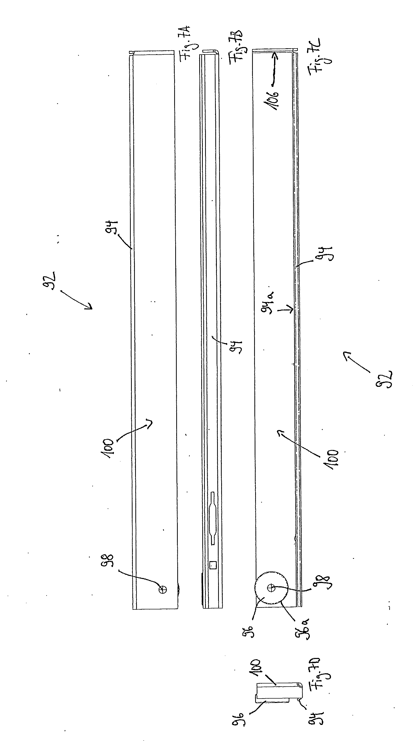
[0042] FIG. 7A a first side view of a pull-out rail;
[0043] FIG. 7B a plan view of the pull-out rail of FIG. 7A;
[0044] FIG. 7C a second side view of the pull-out rail of FIG. 7A;
[0045] FIG. 7D a rear view of the pull-out rail of FIG. 7A;
[0046] FIG. 8 a perspective view obliquely from above of a trouser holder to which the pull-out rail of FIG. 7A and a mirrored pull-out rail are attached at the left and right;
[0047] FIG. 9A a rear view of a clothes rail holder;
[0048] FIG. 9B a side view of the clothes rail holder of FIG. 9A;
[0049] FIG. 9C a front view of the clothes rail holder of FIG. 9A;
[0050] FIG. 9D a plan view from above of the clothes rail holder of FIG. 9A;
[0051] FIG. 9E a view from below of the clothes rail holder of FIG. 9A; and
[0052] FIG. 10 a perspective view of the clothes rail holder of FIG. 9.
[0053] A shelf bracket 10 for a wall shelf is shown in the FIGS. 1A to 10, 2A and 2B. The shelf bracket 10 has a rear end 12, a front end 14, and two side walls 16, 18 spaced apart in parallel. The shelf bracket 10 is brought into a U shape by bending a metal sheet and is thereby substantially closed along a bracket bottom 20, i.e. at its lower side, and is open at its upper side. The side walls 16, 18 of the shelf bracket 10 describe a substantially triangular peripheral shape, with the shelf bracket 10 being higher in the region of its rear end 12 than in the region of its front end 14. While the upper side of the shelf bracket 10 therefor extends substantially horizontally in the installed state, the bracket bottom 20 forms a slanted surface that merges into a peripheral surface in the shape of a quadrant at the front end 14 of the shelf bracket 10.
[0054] The shelf bracket 10 has a T-shaped end section 22a, 22b at a rear end 12 of each side wall 16, 18, said T-shaped end section serving to hang the shelf bracket 10 at a wall rail 24 shown in FIG. 1D. The wall rail 24 can also be called a wall strip. Each T-shaped end section 22a, 22b is formed by a web section 21a, 21b whose length at least approximately corresponds to the wall thickness of the wall rail 24 and by a hook section 23a, 23b that projects therefrom, that extends transversely thereto, and that so-to-say forms the bar of the T-shaped end section 22a, 22b.
[0055] The wall rail 24 has a plurality of pairs of slit-shaped holes 26a, 26b along its main direction of extent which are arranged spaced apart from one another at a specific spacing 28, the so-called grid dimension. Each of the T-shaped end sections 22a, 22b has a maximum height 30 that is longer than a length 32 of the slit-shaped holes 26a, 26b. The T-shaped end sections 22a, 22b of the shelf bracket 10 can hereby only be introduced into the slit-shaped holes 26a, 26b by means of a pivot movement of the shelf bracket 10 about an axis that extends perpendicular to the planes of the side walls 16, 18. The T-shaped end sections 22a, 22b thus not only hold the shelf bracket 10 at the wall rail 24, but they additionally also form a security against removal for the shelf bracket 10. The shelf bracket 10 is thus installed at the wall rail 24 such that, with an upwardly pivoted shelf bracket 10, the upper parts of the hook sections 23a, 23b of the T-shaped end sections 22a, 22b are first introduced into the slit-shaped holes 26a, 26b; the shelf bracket 10 is then pivoted downwardly into a horizontal position so that the lower parts of the hook sections 23a, 23b are also introduced into the slit-shaped holes 26a, 26b; and finally the shelf bracket 10 is displaced downwardly along the wall rail 24 until the web sections 21a, 21b lie on lower boundaries of the slit-shaped holes 26a, 26b. Two pins 34a, 34b additionally project out of the rear side of the shelf bracket 10 that each engage into an adjacent slit-shaped hole 36a, 36b of the wall rail 24 in the installed state of the shelf bracket 10 and contribute to the security against removal. A lateral movement of the shelf bracket 10 relative to the wall rail 24 is additionally limited so that a lateral fixing and guidance of the shelf bracket 10 is effected by the pins 34a, 34b and the holes 36a, 36b.
[0056] The shelf bracket 10 furthermore has a circular hanging hole 38 in the region of its rear end 12 that extends through both side walls 16, 18 and makes it possible to hang the shelf bracket 10 at a goods carrier, not shown, and thus to offer it for sale to a customer.
[0057] A plurality of cut-outs 42a, 42b to 52a, 52b extending into the respective side wall 16, 18 are formed at an upper margin 40a, 40b of each side wall 16, 18 to receive one or more shelf elements. The first cut-outs 42a, 42b form an essentially rectangular groove and are arranged in a rear end region of the shelf bracket 10. The second cut-outs 44a, 44b, 48a, and 48b are arranged along the upper margin 40a, 40b substantially after one third and after two thirds of the total length of the shelf bracket, are formed identically to one another, and each have an undercut 45a, 45b, 49a, 49b. The undercuts 45, 49 serve, for example, to hold a shelf bottom or a wire grid bottom in a shape-matched manner in the cut-out 44, 48. The third cut-outs 46a, 46b, 50a, 50b are formed by slits extending perpendicular from above into the side wall 16, 18. In this respect, the cut-outs 46 are arranged substantially centrally, i.e. spaced apart equally from the front end 14 and from the rear end 12 of the shelf bracket 10 and the cut-outs 50 are arranged in a front end region of the shelf bracket 10. The cut-outs 52 are formed at the front end 14 and are open to the top and to the front. The cut-outs 52 thus have a step-shaped outline in a side view (FIG. 1A).
[0058] Shelf elements such as steel compartment bottoms can be placed in a shape-matched manner into the cut-outs 42, 46, and 52.
[0059] Furthermore, a rectangular hole 54a, 54b that extends in the longitudinal direction of the shelf bracket is formed in each of the side walls 16, 18. The holes 54a, 54b are formed at the shelf bracket 10 in alignment with one another. Together with the slit-shaped cut-outs 50a, 50b formed at the upper margin 40a, 40b in the front end region of the shelf bracket, the holes 54a, 54b serve as coupling means for a guide rail 56 to be fastened to the shelf bracket 10.
[0060] The guide rail 56 is shown more precisely in FIGS. 3A to 4. The guide rail 56 has a rear end 70, a front end 72, and a side wall 74. As can be seen in FIG. 3D, a lower guide rail section 76 and an upper guide rail section 78 project perpendicular from the side wall 74 of the guide rail 56. The guide rail 56 hereby has a C-shaped cross-section at least sectionally.
[0061] A first hook section 80 that extends to the rear is bent outwardly, i.e. in the opposite direction to the guide rail sections 76, 78, out of the side wall 74 in a rear region of the guide rail 56. A front rail section 82 projects upwardly over the upper guide rail section 78 in a front region of the guide rail 56. A second hook section 84 projects from the front rail section 82 in the region of an upper front corner of said front rail section and is likewise bent over outwardly, but extends to the front.
[0062] First part sections 80a, 84a of the hook sections 80, 84 each extend away from the outer side of the side wall 74 and second part sections 80b, 84b then extend substantially in parallel with the side wall 74, but in opposite directions (FIG. 3B). The second part section 80b of the first hook section 80 therefore extends to the rear and the second part section 84b of the second hook section 84 extends to the front.
[0063] The first hook section 80 and the second hook section 84 form a push-lock connection with the cut-out 54a (FIG. 1A) and the slit 50a of the shelf bracket 10 so that the guide rail 56 is fastenable to the shelf bracket 10 without tools, as is shown in FIGS. 5A to 6. For this purpose, the outer side of the side wall 74 of the guide rail 56 is placed onto the outer side of the side wall 16 of the shelf bracket 10 such that the first hook section 80 engages into the cut-out 54a of the shelf bracket 10. The guide rail 56 is then displaced in the direction of the rear end 12 of the shelf bracket 10 relative to the shelf bracket 10 so that the hook section 80 engages behind the first side wall 16 and a part of the side wall 16 is located between the second part section 80b and the side wall 74 of the guide rail 56. The spacing between the hook sections 80, 84, more precisely the spacing between the first part sections 80a, 84a of the hook sections 80, 84 is dimensioned such that the part section 84a of the second hook section 84 of the guide rail 56 can be pushed into the slit 50 with the first hook section 80 already engaging into the shelf bracket 10. In other words, the first hook section 80 can first be pushed into the cut-out 54a until the side wall 16 of the shelf bracket 10 is located between the part section 80b and the side wall 74 of the guide rail 56 and the second hook section 84 can subsequently be hung from above into the slit 50 of the shelf bracket 10.
[0064] As can in particular be seen in FIG. 5A, the upper guide rail section 78 of the guide rail 56 is substantially located beneath the upper margin 40, i.e. approximately one third of the total height of the shelf bracket 10, in the installed state. It is hereby possible to fasten the guide rail 56 and additionally a further shelf element such as a wire bottom, a wooden bottom, or a steel compartment bottom at a side of the shelf bracket 10.
[0065] The guide rail 56 furthermore has a roller 86 (FIG. 3A) that is arranged at the inner side of the guide rail 56 in a front end region of the guide rail 56. The roller 86 is rotatably supported about an axis of rotation 88 that is aligned perpendicular to the plane of the side wall 74.
[0066] The guide rail 56 serves, in conjunction with a mirrored second guide rail 56' (FIG. 6B), for the displaceable support of a shelf element 90 such as the trouser holder 90 shown in FIG. 8, a wooden bottom, a wire basket, or a tray. To be able to pull it out and push it in with as low a friction as possible, a pull-out rail 92 (FIGS. 7A to 7D) is releasably or unreleasably fastened to the shelf element 90 at the left and a mirrored pull-out rail 92' at the right. The pull-out rail 92 has an upper pull-out rail section 94 whose inner side 94a (FIG. 7c) is in contact with a peripheral surface 86a of the roller 86 of the guide rail 56 (FIGS. 3A to 3D) and on whose inner side 94a the roller 86 of the guide rail 56 rolls off on the pulling out and pushing in of the shelf element 90. A roller 96 that is rotatably supported about an axis of rotation 98 that is aligned perpendicular to a plane of a side wall 100 of the pull-out rail 92 is likewise attached to the pull-out rail 92. The peripheral surface 96a of the roller 96 of the pull-out rail 92 lies on an inner side 76a (FIG. 3A) of the lower guide rail section 76 in the assembled state and rolls off on the inner side 76a of the lower guide rail section 76 on the pulling out and pushing closed of the shelf element 90.
[0067] To define a pushed-in state of the shelf element 90, a bulge 102 is provided at the inner side 76 of the lower guide rail section 76 into which bulge the roller 96 of the pull-out rail 92 can roll and is thereby held in a defined position. Furthermore, a push-in abutment 104 shaped from an elastomer is provided at the outer side of the front end 72 of the guide rail 56 and comes into contact with a front end wall 106 (FIG. 7C) of the pull-out rail 92 when the defined pushed-closed state of the shelf element 90 has been reached,
[0068] So that the pull-out rail 92 cannot be pulled out by more than a defined pull-out distance, the rollers 86, 96 are arranged so that they limit a pulling out of the pull-out rail 92 by a mutual abutment of one another. The rollers 96, 96 are disposed for this purpose in the installed state in overlapping height regions and depth regions. A pull-out block is hereby defined by which it is prevented that the shelf element 90 together with the pull-out rail 92 is unintentionally released from the guide rail 56.
[0069] Two mounts 58, 60 for a respective one clothes rail holder 62 (FIG. 9A to 10) are shaped in a front half in the bracket bottom 20 of the shelf bracket 10 (FIG. 1B). Each mount 58, 60 is formed by two slits 58a, 58b and two openings 58c, 58d. To fasten the clothes rail holder 62 to the shelf bracket 10, hook-shaped upper end sections 64a, 64b of the clothes rail holder 62 are introduced into the slits 58a, 58b from below, the clothes line holder is displaced to the front in the direction of the openings 58c, 58d, and the clothes line holder 62 is pulled downward so that front end sections 64c, 64d of the hook-shaped upper end sections 64a, 64b engage into the openings 56c, 58d.
[0070] The clothes rail holder 62 comprises a hook-shaped clothes rail mount or tube mount 108 for receiving a clothes rail, not shown. Two inwardly directed elevated portions 110, 112 are pressed in an end section of the tube mount 108 and secure a clothes rail held by the clothes rail holder 62. To insert the clothes rail into the clothes rail holder 62, the former is clipped into the tube mount 108 over the elevated portions 110, 112. A connection section 114 that is formed in the shape of a single twisted metal sheet is provided between the tube mount 108 and the hook-shaped upper end sections 64a, 64b. This embodiment of the clothes rail holder 62 has the advantage that the clothes rail holder 62 can be shaped inexpensively from a metal sheet.
[0071] Two openings 66, 68 are furthermore provided in the bracket bottom 20 of the shelf bracket 10 (FIG. 1B) through which screws can be led, for example for screwing together a wooden shelf bottom.
[0072] The shelf bracket 10 can also be called a universal support due to its above-described different functions that comprise the mounting of shelf bottoms, the mounting of guide rails for shelf elements that can be pulled out, and the mounting of clothes rail holders and due to the universal applicability resulting therefrom.
REFERENCE NUMERAL LIST
[0073] 10 shelf bracket [0074] 12 rear end of the shelf bracket [0075] 14 front end of the shelf bracket [0076] 16 first side wall of the shelf bracket [0077] 18 second side wall of the shelf bracket [0078] 20 bracket bottom [0079] 21 web section of the T-shaped end section [0080] 22 T-shaped end section [0081] 23 hook section of the T-shaped end section [0082] 24 wall rail or wall strip [0083] 26 slit-shaped hole of the wall rail [0084] 28 grid dimension [0085] 30 maximum height of the T-shaped end section [0086] 32 length of the slit-shaped hole of the wall rail [0087] 34 pin [0088] 36 second slit-shaped hole of the wall rail [0089] 38 hanging hole [0090] 40 upper margin of the shelf bracket [0091] 42 cut-out [0092] 44 cut-out [0093] 45 undercut [0094] 46 cut-out [0095] 48 cut-out [0096] 49 undercut [0097] 50 cut-out [0098] 52 cut-out [0099] 54 hole [0100] 56 guide rail [0101] 58 mount [0102] 58a, 58b slits [0103] 58c, 58d openings [0104] 60 mount [0105] 62 clothes rail holder [0106] 64a, 64b hook-shaped upper end sections [0107] 64c, 64d front end sections [0108] 66 opening [0109] 68 opening [0110] 70 rear end of the guide rail [0111] 72 front end of the guide rail [0112] 74 side wall of the guide rail [0113] 76 lower guide rail section [0114] 76a inner side of the lower guide rail section [0115] 78 upper guide rail section [0116] 80 first hook section [0117] 80a first part section [0118] 80b second part section [0119] 82 front rail section [0120] 84 second hook section [0121] 84a first part section [0122] 84b second part section [0123] 86 roller of the guide rail [0124] 86a peripheral surface of the roller [0125] 88 axis of rotation of the roller [0126] 90 shelf element [0127] 92 pull-out rail [0128] 94 upper pull-out rail section [0129] 94a inner side of the upper pull-out rail section [0130] 96 roller of the pull-out rail [0131] 96a peripheral surface of the roller [0132] 98 axis of rotation of the roller [0133] 100 side wall of the pull-out rail [0134] 102 outer arch [0135] 104 push-in abutment [0136] 106 front wall of the pull-out rail [0137] 108 tube mount [0138] 110 elevated portion for the tube clamping or tube fixing [0139] 112 elevated portion for the tube clamping or tube fixing [0140] 114 connection section
* * * * *
D00000
D00001
D00002
D00003
D00004
D00005
D00006
D00007
D00008
D00009
D00010
XML
uspto.report is an independent third-party trademark research tool that is not affiliated, endorsed, or sponsored by the United States Patent and Trademark Office (USPTO) or any other governmental organization. The information provided by uspto.report is based on publicly available data at the time of writing and is intended for informational purposes only.
While we strive to provide accurate and up-to-date information, we do not guarantee the accuracy, completeness, reliability, or suitability of the information displayed on this site. The use of this site is at your own risk. Any reliance you place on such information is therefore strictly at your own risk.
All official trademark data, including owner information, should be verified by visiting the official USPTO website at www.uspto.gov. This site is not intended to replace professional legal advice and should not be used as a substitute for consulting with a legal professional who is knowledgeable about trademark law.