Cosmetic Compact
Greenfield; Ronald J. ; et al.
U.S. patent application number 15/667896 was filed with the patent office on 2019-02-07 for cosmetic compact. The applicant listed for this patent is CPP GLOBAL. Invention is credited to Christopher Bartoldus, Ronald J. Greenfield, Alex Moskvin.
| Application Number | 20190037998 15/667896 |
| Document ID | / |
| Family ID | 65231746 |
| Filed Date | 2019-02-07 |


| United States Patent Application | 20190037998 |
| Kind Code | A1 |
| Greenfield; Ronald J. ; et al. | February 7, 2019 |
COSMETIC COMPACT
Abstract
A base for a makeup compact includes a singular integrated platform. The platform includes a pan well and one or more shock absorbers including a first end and a second end. The one or more shock absorbers may be coupled to the platform at the first end and include one or more feet coupled to the shock absorbers at the second end. The shock absorbers may mechanically isolate the pan well from mechanical vibrations.
| Inventors: | Greenfield; Ronald J.; (Ronkonkoma, NY) ; Bartoldus; Christopher; (Ronkonkoma, NY) ; Moskvin; Alex; (Ronkonkoma, NY) | ||||||||||
| Applicant: |
|
||||||||||
|---|---|---|---|---|---|---|---|---|---|---|---|
| Family ID: | 65231746 | ||||||||||
| Appl. No.: | 15/667896 | ||||||||||
| Filed: | August 3, 2017 |
| Current U.S. Class: | 1/1 |
| Current CPC Class: | A45D 33/008 20130101; A45D 42/02 20130101; A45D 40/22 20130101; A45D 2033/001 20130101 |
| International Class: | A45D 33/00 20060101 A45D033/00; A45D 40/22 20060101 A45D040/22; A45D 42/02 20060101 A45D042/02 |
Claims
1. A base for a makeup compact comprising: a singular integrated platform, the platform comprising a pan well; one or more shock absorbers comprising a first end and a second end, the one or more shock absorbers coupled to the platform at the first end; one or more feet coupled to the shock absorbers at the second end; wherein the shock absorbers mechanically isolate the pan well from mechanical vibrations.
2. The base of claim 1 further comprising a cover, wherein the cover is hingedly connected to the base to selectively cover and expose the pan well of the base.
3. The base of claim 2 wherein the cover comprises a mirror.
4. The base of claim 1 wherein the one or more shock absorbers are molded as one or more single, continuous, helical pieces extending from the platform optionally formed from a polymer.
5. The base of claim 4 wherein the polymer is selected from nylon, polypropylene, polyethylene, polystyrene, polyvinylchloride, polytetrafluoroethylene or some combination thereof.
6. The base of claim 1 wherein the one or more shock absorbers are formed from a thermosetting plastic selected from vulcanized rubber, Bakelite, Melamine, epoxy resign, phenolics, polyesters, polyimides or some combination thereof.
7. The base of claim 1 wherein the one or more shock absorbers are helically shaped.
8. The base of claim 7 wherein the one or more shock absorbers have a constant radius of curvature about a central axis along a height of the one or more shock absorbers.
9. The base of claim 7 wherein the one or more shock absorbers have a varying radius of curvature about a central axis along a height of the one or more shock absorbers.
10. A compact for storing makeup, the compact comprising: a frame; a platform comprising one or more shock absorbers and a pan well; and a base; wherein the frame and one or more shock absorbers are coupled to the base, wherein the one or more shock absorbers mechanically isolate the pan well from the base.
11. The compact of claim 10. wherein the compact further comprises a cover comprising a cover hinge and a front lip bump, and the frame further comprises a frame hinge and a frame bump, and the cover hinge and the frame hinge share a common axis of rotation and are configured to allow the cover to rotate about the common axis of rotation, and the front lip bump and the frame bump are configured to selectably friction fit the cover with the frame.
12. The compact of claim 10 wherein the one or more shock absorbers are molded as a single, continuous, helical pieces extending from the platform formed from a polymer.
13. The base of claim 12 wherein the polymer is selected from nylon, polyethylene, polystyrene, polyvinylchloride, polytetrafluoroethylene or some combination thereof.
14. The base of claim 10 wherein the one or more shock absorbers are formed from a thermosetting plastic selected from vulcanized rubber, Bakelite, Melamine, epoxy resign, phenolics, polyesters, polyimides or some combination thereof.
15. The base of claim 10 wherein the one or more shock absorbers are helically shaped.
16. The base of claim 15 wherein the one or more shock absorbers have a constant radius of curvature about a central axis along a height of the one or more shock absorbers.
17. The base of claim 15 wherein the one or more shock absorbers have a varying radius of curvature about a central axis along a height of the one or more shock absorbers.
18. A method of isolating a pan well of a makeup compact from mechanical vibrations affecting the makeup compact comprising: providing a compact comprising a platform and a base, wherein the platform comprises one or more shock absorbers and the pan well, and placing makeup within the pan well.
19. The method of claim 18 wherein the one or more shock absorbers are molded as one or more single, continuous, helical pieces extending from the platform formed from a polymer.
20. The method of claim 19 wherein the polymer is selected from nylon, polyethylene, polystyrene, polyvinylchloride, polytetrafluoroethylene or some combination thereof.
Description
BACKGROUND
Field
[0001] The present disclosure relates to cases for makeup or cosmetic compacts. More particularly, the present invention relates to a cosmetic compact having one or more helical supports for isolating a makeup pan well from the cosmetic compact.
Technical Background
[0002] Cosmetic compacts or makeup cases ("compacts") hold makeup or cosmetics (foundation, blush, lipstick, eyeliner, eyeshadow, etc.). Compacts may have one or more compartments for holding makeup, utensils, pads, or other items associated with the application of makeup. Additionally, compacts may have a mirror to enable the user to view his or her face while applying the makeup. Compacts may be configured as a single unit having a hinged opening that opens to allow the user to view the mirror.
[0003] It may be advantageous to isolate the contents of a compact from mechanical shocks or vibrations. Such isolation might prevent the contents from breaking, spilling, or otherwise leaving the compact. One such implementation might be one or more shock absorbers taking the shape of a spring that dampens or absorbs the impact on the outer casing from affecting the pan well.
BRIEF SUMMARY
[0004] According to the subject matter of the present disclosure, a base for a makeup compact includes a singular integrated platform. The platform comprises a pan well and one or more shock absorbers including a first end and a second end. The one or more shock absorbers may be coupled to the platform at the first end and include one or more feet coupled to the shock absorbers at the second end. The shock absorbers may mechanically isolate the pan well from mechanical vibrations.
[0005] In accordance with one embodiment of the present disclosure, a compact for storing makeup comprises a frame, a platform comprising one or more shock absorbers and a pan well, and a base. The frame and shock absorbers may be coupled to the base, such that the shock absorbers mechanically isolate the pan well from the base.
[0006] In accordance with another embodiment of the present disclosure, a method of isolating the contents of a makeup compact from mechanical vibrations affecting the compact comprises providing a compact comprising a platform and a base, wherein the platform comprises one or more shock absorbers and a pan well, and placing makeup within the pan well.
[0007] Although the concepts of the present disclosure are described herein with primary reference to a makeup compact, it is contemplated that the concepts will enjoy applicability to any structure for isolating a platform mechanically. For example, and not by way of limitation, it is contemplated that the concepts of the present disclosure will enjoy applicability to any type of platform mechanically isolated from a base structure.
BRIEF DESCRIPTION OF THE SEVERAL VIEWS OF THE DRAWINGS
[0008] The following detailed description of specific embodiments of the present disclosure can be best understood when read in conjunction with the following drawings, where like structure is indicated with like reference numerals and in which:
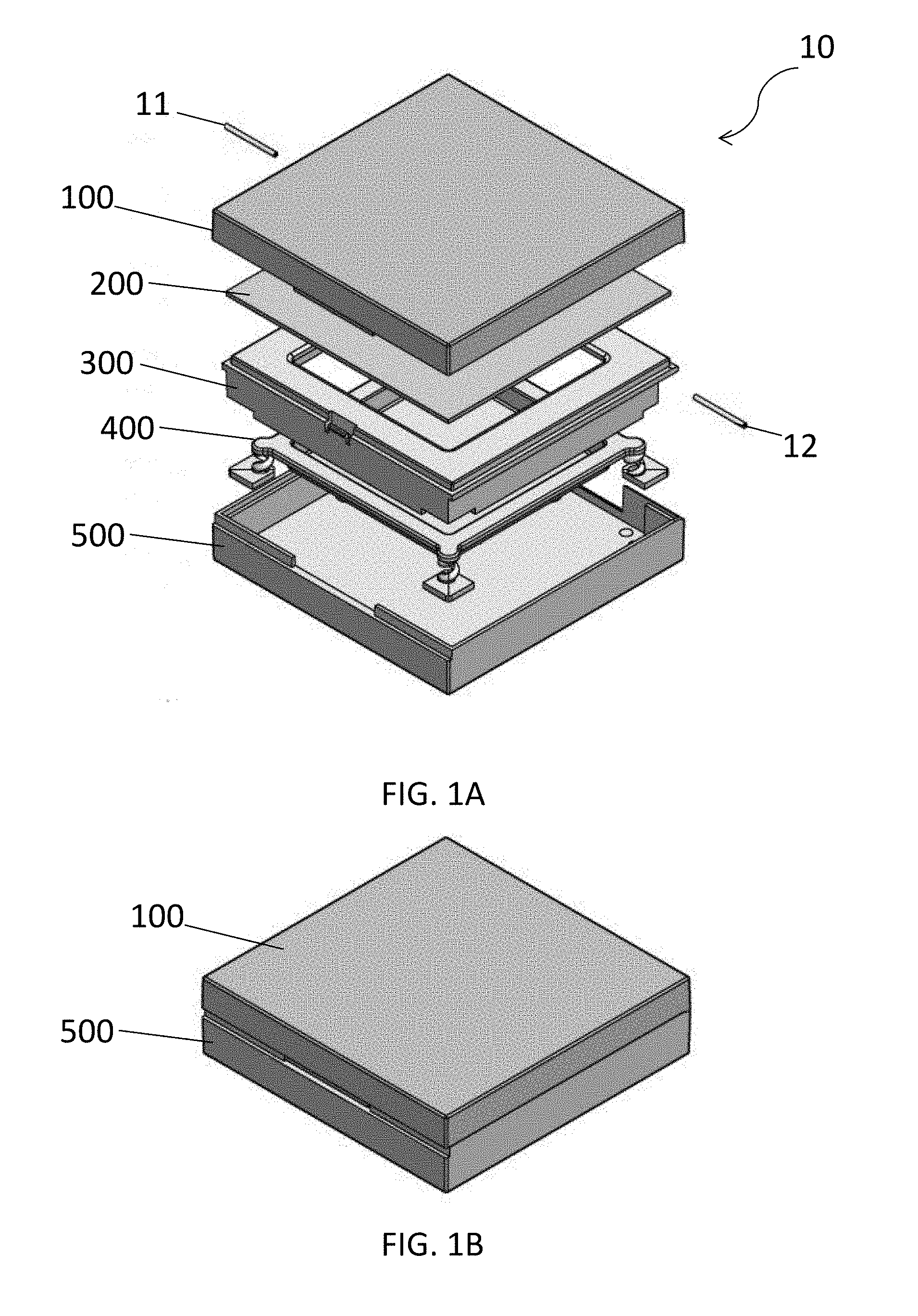
[0009] FIG. 1A shows an exploded isometric view of a makeup compact according to some aspects as provided herein;
[0010] FIG. 1B shows the makeup compact of FIG. 1A in a closed position;
[0011] FIG. 1C shows a frontal cross-sectional view of the makeup compact of FIG. 1A;
[0012] FIG. 1D shows a side cross-sectional view of the makeup compact of FIG. 1A;
[0013] FIG. 1E shows a zoomed-in view of the makeup compact of FIG. 1D;
[0014] FIG. 2A shows an isometric view of a pan well in isolation according to some aspects as provided herein;
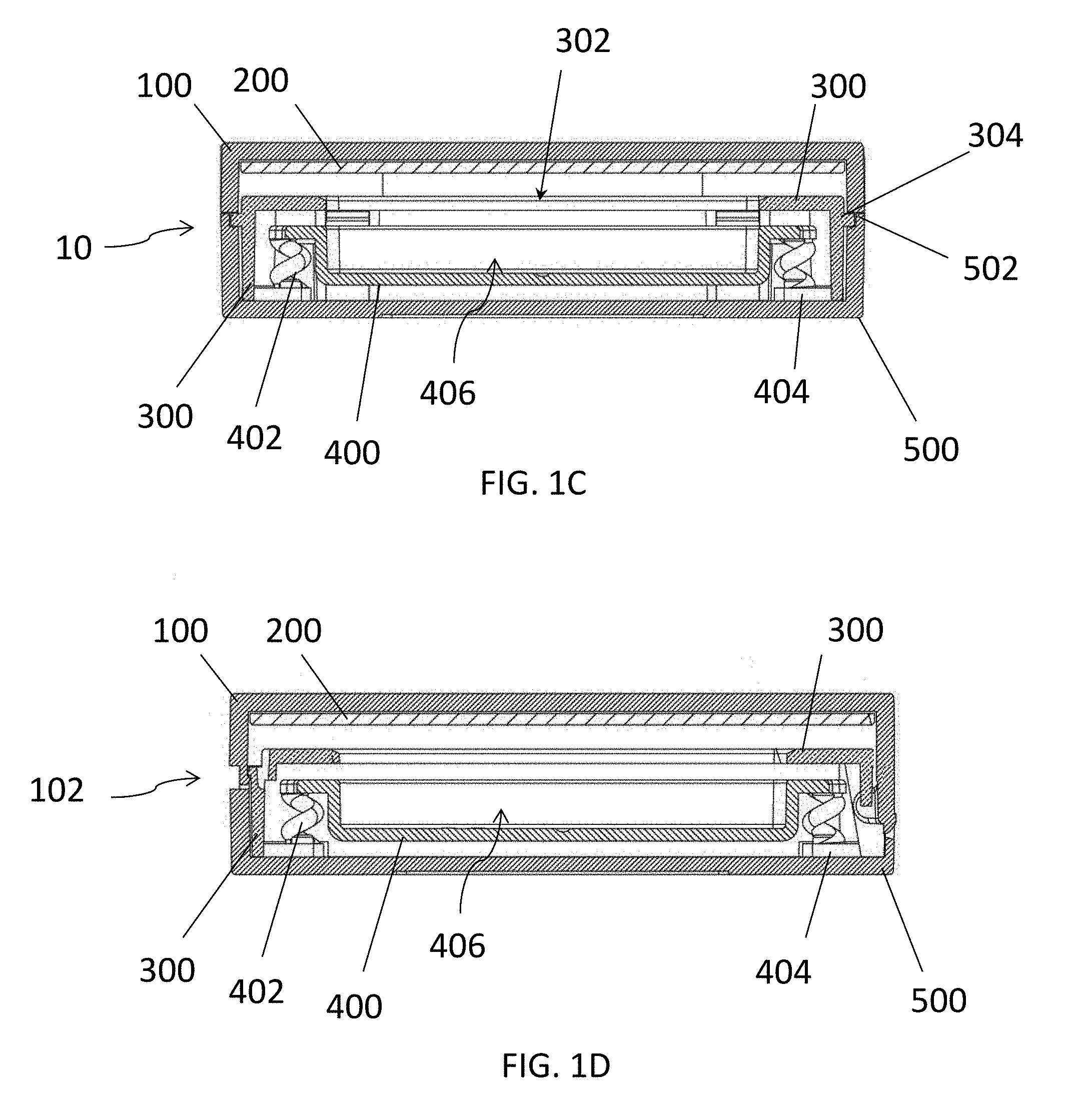
[0015] FIG. 2B shows the bottom of the pan well of FIG. 2A;
[0016] FIG. 2C shows a side cross-sectional view of the pan well of FIG. 2A;
[0017] FIG. 2D shows a cross-sectional view of an aspect of the pan well of FIG. 2A;
[0018] FIG. 3A shows an isometric view of the bottom of the base of the makeup compact of FIG. 1A in isolation;
[0019] FIG. 3B shows a top view of the base of FIG. 3A;
[0020] FIG. 4A shows an isometric view of the top of the cover of the makeup compact of FIG. 1A;
[0021] FIG. 4B shows a bottom view of the cover of FIG. 4A;
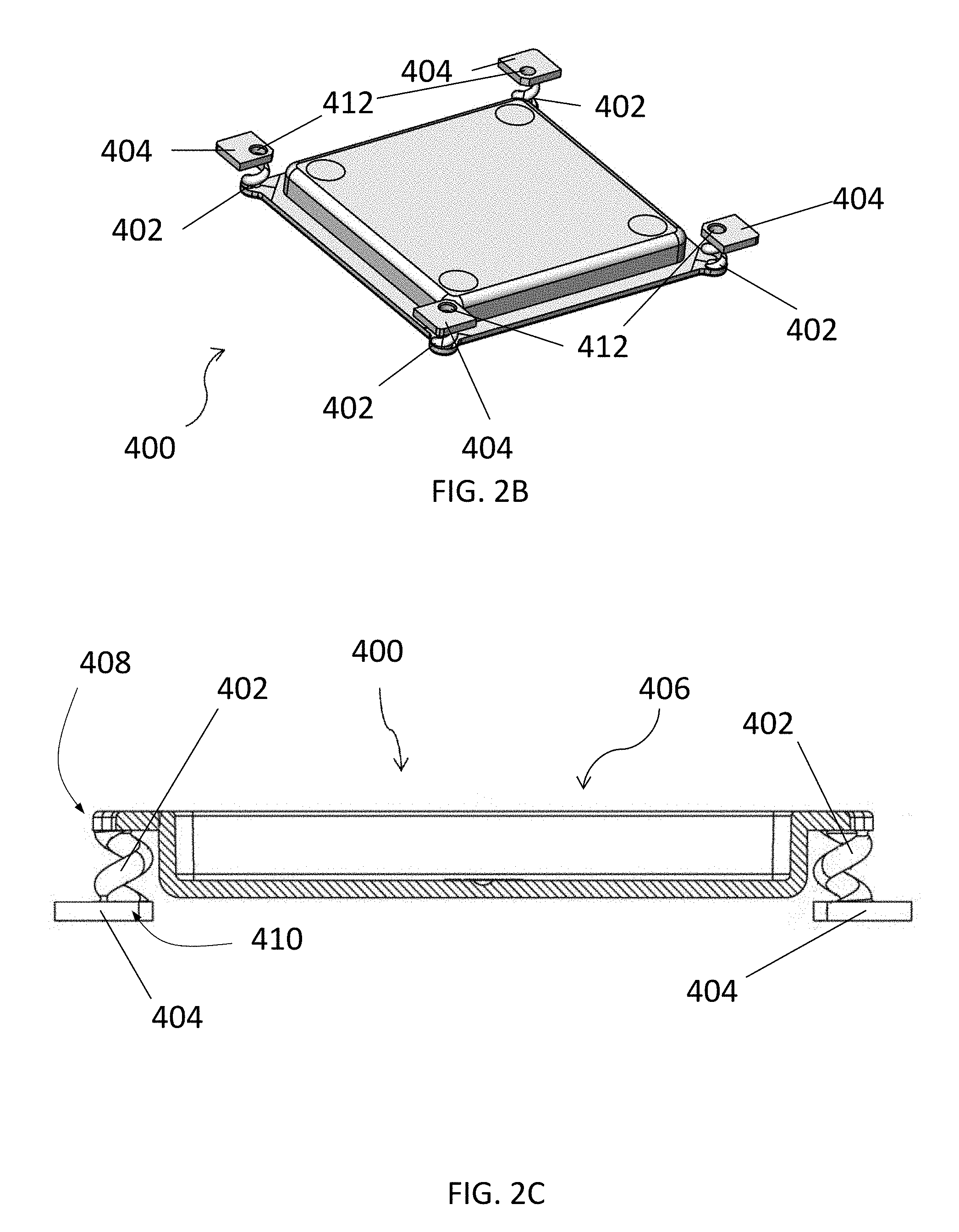
[0022] FIG. 4C shows a side view of the cover of FIG. 4A;
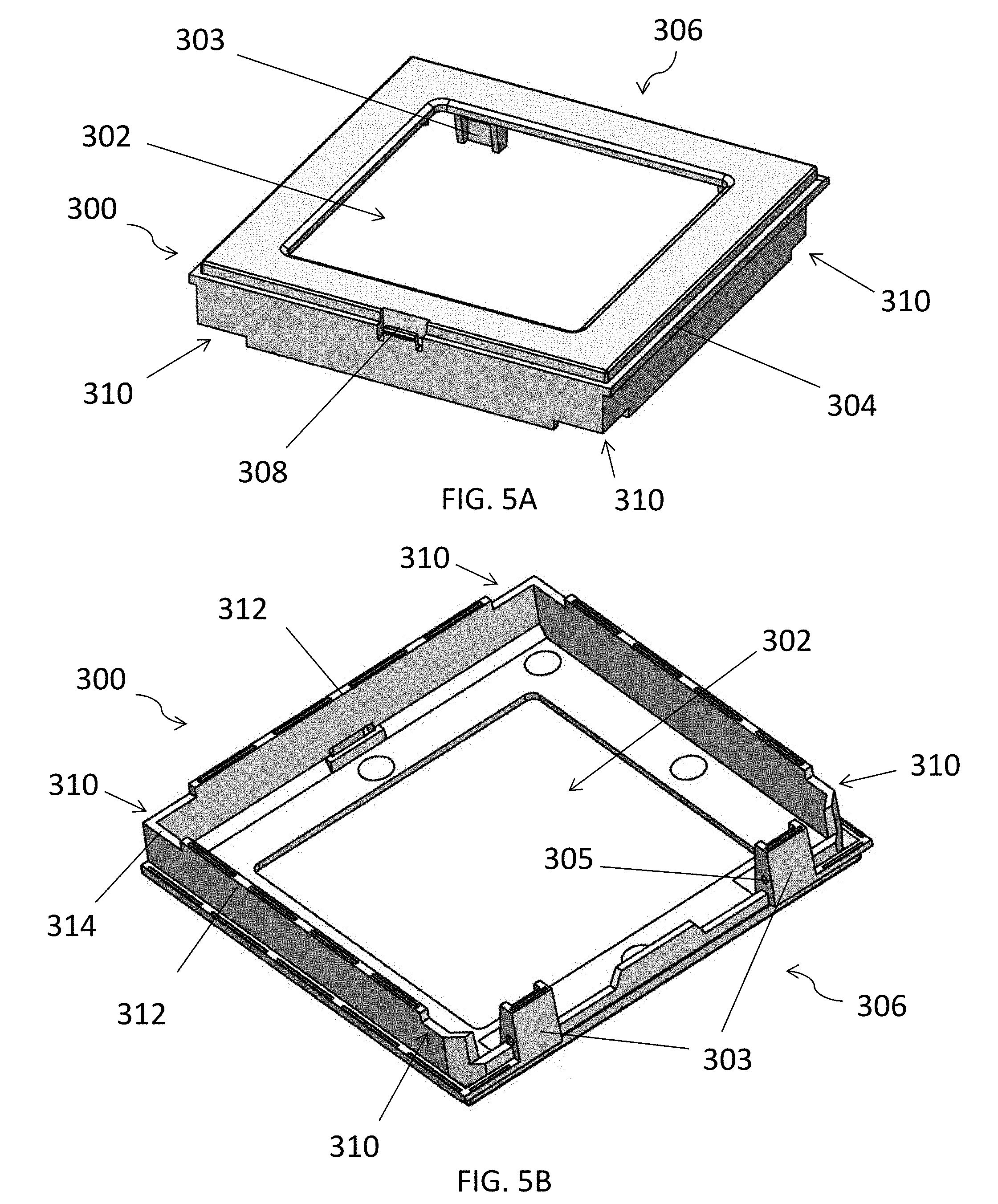
[0023] FIG. 5A shows an isolated view of the frame of the makeup compact of FIG. 1A; and
[0024] FIG. 5B shows a bottom view of the frame of FIG. 5A.
DETAILED DESCRIPTION
[0025] Referring initially to FIG. 1A, a compact 10 is shown. The compact 10 may comprise a cover 100, a mirror 200, a frame 300, a platform 400, and a base 500. The cover 100 and the base 500 enclose the mirror 200, frame 300, and platform 400 by pivoting about pins 11, 12 between an open and a closed (as shown in FIG. 1B) position of the compact 10. The cover 100 and base 500 of the compact 10 may generally comprise a quadrangular shape but other three-dimensional forms are contemplated, such as, for example, circles, ovals, pentagonals, etc. so long as the mirror 200, frame 300, and platform 400 may be formed to generally fit within the compact 10. Components of the compact 10 may be injection molded, vacuum formed or molded or thermally formed. The components may be formed from thermoplastics, thermosetting polymers, elastomers, metals or glass. Optionally, certain aspects of the compact 10 exclude the use of thermosetting polymers or thermosetting plastics.
[0026] As shown in FIG. 1C, the mirror 200 may be disposed within the cover 100 and the frame 300 and the platform 400 are disposed inside the base 500. The base 500 includes notch 502 and prevents lateral movement of the platform 400 and frame 300 and may be connected to the platform 400 and frame 300 as described below. The notch 502 couples to the shoulders 304 of the frame 300 to help stabilize the frame 300 and prevent movement of the frame 300 within the base 500.
[0027] The mirror 200 comprises a reflective surface that allows the user to view his or her own face, such as, for example, when applying makeup or other contents of the compact 10. The mirror 200 may be affixed to the inside of the cover 100 by a glue, epoxy, or a dual-side adhesive but embodiments are contemplated in which the mirror 200 is attached to the inside of the cover 100 using any appropriate means. The mirror 200 may fill substantially all the inside surface of the cover 100 or only a portion thereof, leaving some space for other uses of the inside surface of the cover 100, such as, for example, a transparent window that allows the user to see the contents of the compact 10. The mirror 200 may take a similar or different shape than the compact 10, such as, for example, a circular mirror in a square compact, or vice-a-versa. Optionally, certain aspects of the compact 10 exclude a mirror.
[0028] The frame 300 includes an opening 302 and shoulders 304. The opening 302 provides access to the contents of the pan well 406 and may house other objects, such as, for example, a makeup applicator (not shown). The shoulders 304 are in mechanical communication with the notch 502 of the base 500 and stabilize the frame 300 and help prevent movement of the frame 300 within the base 500.
[0029] The platform 400 includes shock absorbers 402, feet 404, and pan well 406. The shock absorbers 402 and feet 404 couple the pan well 406 to the compact 10 such that some mechanical shock imparted on the compact 10 is mechanically isolated from the pan well 406. Hence, the contents of the pan well 406, such as, for example, makeup, is mechanically isolated from shocks or vibrations acting upon the compact 10. The feet 404 comprise one or more protrusions that are substantially flat surfaces and may about the frame 300 and/or the base 500 along one or more of their respective surfaces to prevent transverse movement of the platform 400 relative to the frame 300 and the base 500. The pan well 406 holds the makeup or other contents of the compact 10.
[0030] The platform 400 may be formed as a singular integrated platform. In some aspects, the components of the platform 400, such as the shock absorbers 402, the feet 404, and the pan well 406 are molded or made from a single continuous piece. In other aspects, the shock absorbers 402, the feet 404, and the pan well 406 are made from a single material such as, for example, polyethylene or polypropylene. In some aspects, components of the platform 400 are formed using a single mold.
[0031] As shown in FIGS. 1D and 1E, the frame 300 may interact with the cover 100 and base 500 to form the hinge and friction fit mechanisms with the cover 100 to open and close the compact 10 as will be described in greater detail below. The cover 100 is pivotably selectable between an open position and a closed position. A friction fit 13 between the cover 100 and the frame 300 is formed to secure the cover 100 in the closed position. When in the closed position, movement of the cover 100 is restrained by the friction fit 13 and one or more pins 11, 12 coupling the frame 300 to the cover 100 through the frame hinge 306 (best shown in FIGS. 4B and 5B).
[0032] FIGS. 2A-2C show the platform 400 in detail. As described above, the platform 400 is mechanically isolated from the cover 100 and base 500 of the compact 10 by one or more shock absorbers 402. The shock absorbers 402 comprise a first end 408 and a second end 410. The shock absorbers 402 couple to the platform 400 at the first end 408 and to the feet 404 at the second end 410. The shock absorbers 402 may serve as a spring or a damper to absorb or dampen the mechanical energy associated with mechanical shock or vibration of the compact 10. The shock absorbers 402 may be formed from a plastic material such as polypropylene or polyethylene. The shock absorbers 402 may be formed from a single mold or multiple, individual molds and be molded as a single, continuous, helical piece formed from a polymer, optionally a high molecular weight polymer. Illustrative examples of a polymer include but are not limited to nylon, polyethylene, polypropylene, polystyrene, polyvinyl chloride (PVC), and polytetrafluoroethylene (PTFE). Additionally, the shock absorbers 402 may be formed from a thermosetting plastic such as vulcanized rubber, Bakelite, Melamine, epoxy resins, phenolics, polyesters, and polyimides. In some aspects, the composition of the shock absorbers 402 excludes thermosetting plastic.
[0033] The shock absorbers 402 may extend and contract longitudinally along a central axis of the shock absorber 402. In some embodiments, the shock absorbers 402 are helically shaped and may form a helical spring to absorb shock or vibrations imparted on the compact 10. Some embodiments of the shock absorber 402 will have a constant radius of curvature about a central axis along the height of the shock absorber 402. However, embodiments are contemplated in which the radius of curvature is not constant along a height of the shock absorber 402, such that the shock absorber 402 has a varying radius of curvature about a central radius of a shock absorber. Optionally, aspects of the shock absorber 402 exclude shock absorbers in the form of solid or hollow cylinders such as, for example, solid or hollow cylinders formed from resilient materials, such as rubber, polymer, or other deformable and resilient materials.
[0034] FIG. 2D shows an aspect of the compact 10 that includes a helical shock absorber 403 having a lateral cross section that is rectangular or square such that a vertical cross section from the side of the shock absorber 402 may be trapezoidal in shape. The rectangular cross section may include a height that is greater than the thickness of the cross section.
[0035] In some embodiments, a shock absorber may be a single, double, or triple helix in design. Optionally, a shock absorber is a double helix in design. A double or triple helix design of the shock absorber 403 may provide greater stiffness characteristics than other designs, such as shock absorber 402. In certain aspects, the double-helical design may increase shock or vibration absorption. In such embodiments, replacing the spherical lateral cross section of the shock absorber 402 with a shock absorber having a trapezoidal lateral cross section such as shock absorber 403 increases the resilience (U.sub.r) of the shock absorbers 402.
[0036] The vibrations or shock felt by the compact 10 may be imparted on the compact 10 during testing of the compact 10. For example, the compact 10 may be tested using the Inclined Plane Testing to Determine Pressed Powder, Packaging Test Procedure ("IPTDPP"). The IPTDPP is designed to provide a uniform method to determine a pressed powder's ability to withstand damage as a result of normal use. The test uses a compact support car (775 grams in weight) having wheels fit within the grooves built on a 43 inch long thirty-degree inclined plane and rubber bands that hold a compact to the compact support car as it travels down the inclined plane. The test measures the ability of a compact, such as compact 10, to avoid breaking or having components become dislodged due to vibrations or shocks imparted on the compact 10 during the test and for the powder within the compact 10 to avoid cracking or crumbling.
[0037] Some embodiments of the platform 400 have four shock absorbers 402, but embodiments are not so limited. For example, in embodiments of a compact having a generally triangular shape, a triangular platform may have 3 shock absorbers, and in a pentagonal or hexagonal compact, the platform may have five or six shock absorbers, respectively. The number of shock absorbers may be equal to the number of corners on a platform, but need not be so limited. Optionally, the number of shock absorbers is greater or less than the number of corners. The shock absorbers 402 lift the platform 400 high enough such that the bottom of the pan well 406 does not contact the base 500 of the compact 10 during normal operations or upon impact of the compact 10.
[0038] Embodiments of the platform 400 may generally take a square shape or match the shapes of the cover 100 and base 500 for fitting within the compact 10 but additional shapes of the components comprising the compact 10 are contemplated such as round, oval, non-square rectangle, triangle, pentagon, hexagon, or other. The pan well 406 may be bounded by pan well sidewall 414 and have a depth appropriate to hold a sufficient amount of makeup or other substance. The pan well 406 may end at a pan well topwall 416. It is contemplated that while the platform 400 in the particular embodiment shown comprises a single pan well 406, embodiments are contemplated having two or more pan wells for holding two or more similar or different types of makeup, such as, for one example, a base and an eyeliner, or a base and a base or various application tools for applying the contents of the compact 10.
[0039] As shown in FIG. 2C, the feet 404 may include holes 412. The holes 412 may receive pegs 510 (FIG. 3B) of the base 500. The hole and peg arrangement may prevent transverse movement of the platform 400 inside the frame 300. Additionally, the feet 404 may be formed in a shape that is complementary with the inner wall of the base 500. Thus, the mechanical coupling of the feet 404 and the inner wall of the base 500 may form a friction fit, or a snap fit, with the base 500 holding the platform 400 in place during regular operation of the compact 10. Optionally, the feet 404 include additional protrusions for fixing the movement of the platform 400 relative to the movement of the base 500, such as, for example, pins, bumps, or ridges. In such embodiments, the base 500 may include complementary indentations, for receiving such pins, bumps, or ridges. In some aspects, the base 500 may include the protrusions and the feet 404 may include complementary indentations.
[0040] With reference to FIGS. 3A and 3B, bottom and top views of the base 500 of the compact 10 are shown, respectively. The base 500 includes notches 502, cutout 503, front edge 504, shoulder(s) 506, space 508, peg(s) 510 and label well 512.
[0041] As described above, notches 502 provide a mechanical interface for the shoulders 304 of the frame 300 to contact. Cutout 503 provides space for the extension 112 of the cover 100 described below. The front edge 504 encloses the compact 10 along a front side of the compact 10. The shoulder 506 provides a clearance for the cover 100 and may allow a user's finger to catch the cover 100 in order to open the cover 100. The space 508 provides room for the frame bump 308 to project forward of the base 500 for forming the friction fit 13 between the frame 300 and the cover 100. The pegs 510 form a friction fit with the holes 412 inside the feet 404 of the shock absorbers 402 to prevent movement of the platform 400 relative to the base 500. The label well 512 provides a dedicated space for applying a manufacturer's label or describing the contents of the compact 10.
[0042] Referring to FIGS. 4A-4C, the cover 100 is shown in greater detail. The cover 100 includes a front wall 102, a rear wall 104, a top 106, two sidewalls 108, and a front wall 110, an extension 112, a cover hinge 114, one or more holes 116, and a front lip bump 118. The front wall 102 projects downward from the cover 100 and holds the front lip bump 118 that forms the friction fit 13 with the frame bump 308 to keep the cover 100 closed. The front wall 102, rear wall 104, sidewalls 108 enclose the compact 10 keeping the contents inside the compact 10. The extension 112 extends down from the rear wall 104 for connecting the cover hinge 114 of the cover 100 to the frame hinge 306 of the frame 300. Pins 11 may be inserted into holes 116 to mechanically couple the cover 100 and the frame 300 at the frame hinge 306. The front lip bump 118 that, as described above, forms a friction fit 13 with the frame bump 308 to keep the cover closed. This friction fit 13 may be referred to as a snap closure. Optionally, some aspects exclude a friction fit using one or more spheres or equivalent structures mechanically coupled to one or more springs, wherein the one or more springs force the one or more spheres into mechanical communication with one another or another component of the cover 100 or base 500 creating a friction fit. Further, aspects optionally exclude a cover closure device using one or more magnets placed on the cover 100 and the base 500.
[0043] In some embodiments, the cover 100 further comprises the cover hinge 114 and the front lip bump 118, and the frame 300 further comprises the frame hinge 306 and the frame bump 308, and the cover hinge 114 and the frame hinge 306 share a common axis of rotation (not shown) and are configured to allow the cover 100 to rotate about the common axis of rotation, and the front lip bump 118 and the frame bump 308 are configured to selectably friction fit the cover 100 with the frame 300.
[0044] Referring to FIGS. 5A-5B, the frame 300 of the compact 10 is shown. The frame 300 includes opening 302, posts 303, shoulders 304, frame hinge 306 with holes 305, frame bump 308, cutouts 310, bottom edge 312, and cutout bottom edges 314. The frame 300 may be set inside the base 500 and secured using an epoxy or glue. In some embodiments, the frame 300 may be friction fit within the base 500. As described above, the opening 302 provides access to the contents of the pan well 406. The posts 303 provide mechanical clearance and holes 305 for frame hinge 306 for hingedly connecting the cover 100 to the frame 300. The hinge may be a metal pin hinge or a snap hinge. The frame 300 couples to the base 500 and the cover 100 is thus hingedly coupled to the base 500 through the frame 300. In this way, the cover 100 closes and opens to allow access to the contents of the compact 10. The frame bump 308 forms friction fit 13 with the front lip bump 118.
[0045] The cutouts 310 fit over the feet 404 of the platform 400. The cutouts 310 provide a mechanism for the frame 300 to straddle the feet 404 so that the platform 400 and the frame 300 can both couple directly to the base 500. Accordingly, the cutout bottom edge 314 may contact the upper surface of feet 404. The bottom edge 312 of the frame 300 may form a friction fit with the base 500 or may be glued or epoxied to base 500.
[0046] To assemble the compact 10, the platform 400 is placed inside the base 500 first. The holes 412 in the feet 404 of the platform 400 are aligned with the pegs 510 in the base 500 and the platform 400 is situated inside the base 500 such that the sides of the feet 404 contact the inner walls of the base 500 at the corners of the base 500. The corners of the feet 404 and the corners of the base 500 and/or the holes 412 and the pegs 510 may form a friction fit that keeps the platform 400 in place while the compact 10 is moved. For example, if the compact 10 is held upside down, such as in a user's purse, for example, the platform 400 will remain in place with respect to the base 500. In this way, the makeup inside the pan well 406 remains in the pan well 406 and does not contact other portions of the compact 10.
[0047] The frame 300 and the cover 100 are pinned or otherwise hingedly fixed together in a manner that allows hinged movement between the cover 100 and the frame 300. The cover 100 is pinned (or otherwise hingedly fixed) to the frame 300 using pins or other means, such as pins 11, 12. This allows pivotal movement of the cover 100 In some embodiments, the maximum angle of relative rotation between the cover 100 and the frame 300 may be 110 degrees. The frame 300 with the cover 100 attached is then placed inside the base 500 with the bottom edge 312 down inside the base 500. The frame 300 may be epoxied, glued, or otherwise friction fit within the base 500 to prevent removal or movement of the frame 300 and through the hinged connection, the cover 100, from the base 500. In some embodiments, such as, for example, when the frame 300 is friction fit within the base 500, the frame 300 and base 500 may form a modular assembly. Once the frame 300 with cover 100 attached is placed within the base 500, the user can open and close the compact 10 by swinging the cover 100 about the cover hinge 114.
[0048] In modular embodiments, users might place and replace various platforms having different contents within the one or more pan wells inside the same compact 10. For example, a user might remove the frame 300 and cover 100 from the base 500, exposing the platform 400. The user may then remove the platform 400 having, for example, blush, and replace it with a platform 400 that has eyeliner. The user could then replace the frame 300 and cover 100, locking the new platform 400 having eyeliner in place. In this way, platforms having different contents in different pan wells can be interchanged between the same makeup compact 10, increasing user choice and decreasing the number of new parts that need to be manufactured in order to provide users with a wide selection of different types of makeup.
[0049] For the purposes of describing and defining the present invention, it is noted that reference herein to a characteristic of the subject matter of the present disclosure being a "function of" a parameter, variable, or other characteristic is not intended to denote that the characteristic is exclusively a function of the listed parameter, variable, or characteristic. Rather, reference herein to a characteristic that is a "function" of a listed parameter, variable, etc., is intended to be open ended such that the characteristic may be a function of a single parameter, variable, etc., or a plurality of parameters, variables, etc.
[0050] It is also noted that recitations herein of "at least one" component, element, etc., should not be used to create an inference that the alternative use of the articles "a" or "an" should be limited to a single component, element, etc.
[0051] It is noted that recitations herein of a component of the present disclosure being "configured" or "programmed" in a particular way, to embody a particular property, or to function in a particular manner, are structural recitations, as opposed to recitations of intended use. More specifically, the references herein to the manner in which a component is "configured" or "programmed" denotes an existing physical condition of the component and, as such, is to be taken as a definite recitation of the structural characteristics of the component.
[0052] It is noted that terms like "preferably," "commonly," and "typically," when utilized herein, are not utilized to limit the scope of the claimed invention or to imply that certain features are critical, essential, or even important to the structure or function of the claimed invention. Rather, these terms are merely intended to identify particular aspects of an embodiment of the present disclosure or to emphasize alternative or additional features that may or may not be utilized in a particular embodiment of the present disclosure.
[0053] For the purposes of describing and defining the present invention it is noted that the terms "substantially" and "approximately" are utilized herein to represent the inherent degree of uncertainty that may be attributed to any quantitative comparison, value, measurement, or other representation. The terms "substantially" and "approximately" are also utilized herein to represent the degree by which a quantitative representation may vary from a stated reference without resulting in a change in the basic function of the subject matter at issue.
[0054] Having described the subject matter of the present disclosure in detail and by reference to specific embodiments thereof, it is noted that the various details disclosed herein should not be taken to imply that these details relate to elements that are essential components of the various embodiments described herein, even in cases where a particular element is illustrated in each of the drawings that accompany the present description. Further, it will be apparent that modifications and variations are possible without departing from the scope of the present disclosure, including, but not limited to, embodiments defined in the appended claims. More specifically, although some aspects of the present disclosure are identified herein as preferred or particularly advantageous, it is contemplated that the present disclosure is not necessarily limited to these aspects.
[0055] It is noted that one or more of the following claims utilize the term "wherein" as a transitional phrase. For the purposes of defining the present invention, it is noted that this term is introduced in the claims as an open-ended transitional phrase that is used to introduce a recitation of a series of characteristics of the structure and should be interpreted in like manner as the more commonly used open-ended preamble term "comprising."
* * * * *
D00000
D00001
D00002
D00003
D00004
D00005
D00006
D00007
D00008
D00009
XML
uspto.report is an independent third-party trademark research tool that is not affiliated, endorsed, or sponsored by the United States Patent and Trademark Office (USPTO) or any other governmental organization. The information provided by uspto.report is based on publicly available data at the time of writing and is intended for informational purposes only.
While we strive to provide accurate and up-to-date information, we do not guarantee the accuracy, completeness, reliability, or suitability of the information displayed on this site. The use of this site is at your own risk. Any reliance you place on such information is therefore strictly at your own risk.
All official trademark data, including owner information, should be verified by visiting the official USPTO website at www.uspto.gov. This site is not intended to replace professional legal advice and should not be used as a substitute for consulting with a legal professional who is knowledgeable about trademark law.