Method and Apparatus for a Software-Seamed and Augmented View of an Asynchronous Network Fabric
Iyengar; Praveen Parthasarathy ; et al.
U.S. patent application number 15/662319 was filed with the patent office on 2019-01-31 for method and apparatus for a software-seamed and augmented view of an asynchronous network fabric. This patent application is currently assigned to Cisco Technology, Inc.. The applicant listed for this patent is Cisco Technology, Inc.. Invention is credited to Narayanaswami Ganapathy, Praveen Parthasarathy Iyengar, Srinivas Pitta, Shrawan Chittoor Surender.
| Application Number | 20190034477 15/662319 |
| Document ID | / |
| Family ID | 65038662 |
| Filed Date | 2019-01-31 |

| United States Patent Application | 20190034477 |
| Kind Code | A1 |
| Iyengar; Praveen Parthasarathy ; et al. | January 31, 2019 |
Method and Apparatus for a Software-Seamed and Augmented View of an Asynchronous Network Fabric
Abstract
Methods and systems for tracking transactions in a network fabric, include: receiving a message generated by a node in the network fabric; assigning a uniform fabric identifier ("UFID") to the node; assigning a uniform transaction identifier ("UTID") to the message"; appending the UFID and the UTID to the message; and storing the message in a database.
| Inventors: | Iyengar; Praveen Parthasarathy; (Milpitas, CA) ; Surender; Shrawan Chittoor; (Sunnyvale, CA) ; Ganapathy; Narayanaswami; (Fremont, CA) ; Pitta; Srinivas; (Cupertino, CA) | ||||||||||
| Applicant: |
|
||||||||||
|---|---|---|---|---|---|---|---|---|---|---|---|
| Assignee: | Cisco Technology, Inc. San Jose CA |
||||||||||
| Family ID: | 65038662 | ||||||||||
| Appl. No.: | 15/662319 | ||||||||||
| Filed: | July 28, 2017 |
| Current U.S. Class: | 1/1 |
| Current CPC Class: | G06F 16/2379 20190101; G06F 9/546 20130101; H04L 67/146 20130101; H04L 69/08 20130101; H04L 67/36 20130101; G06F 16/2477 20190101; G06F 16/258 20190101; G06F 16/955 20190101 |
| International Class: | G06F 17/30 20060101 G06F017/30; H04L 29/08 20060101 H04L029/08; H04L 29/06 20060101 H04L029/06; G06F 9/54 20060101 G06F009/54 |
Claims
1. A method of tracking transactions in a network fabric, comprising: receiving a message generated by a node in the network fabric; assigning a uniform fabric identifier ("UFID") to the node; assigning a uniform transaction identifier ("UTID") to the message"; appending the UFID and the UTID to the message; and storing the message in a database.
2. The method of claim 1, wherein the UFID is unique to the network fabric.
3. The method of claim 1, wherein the UTID is a sequentially generated number unique to the node.
4. The method of claim 1, wherein the message is a message and transaction service ("MTS") high performance interprocess communications message.
5. The method of claim 4, wherein assigning the UFID and the UTID to the message further comprises placing the UFID and the UTID in the header of the message.
6. The method of claim 1, further comprising converting the message into a common format prior to storing the message in the database.
7. The method of claim 6, further comprising generating a notification upon storing the message in the database.
8. The method of claim 6, further comprising responding to a database query for a message with the message and other associated messages having comparable time stamps.
9. A system of nodes arranges in a fabric, comprising: a first node associated with a first unique-to-the-fabric fabric identifier ("UFID") and a counter providing a first unique-to-the-node transaction identifier ("UTID"), the first node operable to generate a first message with a header including the first UFID and the first UTID; a second node associated with a second unique-to-the-fabric fabric identifier ("UFID") and a counter providing a second unique-to-the-node transaction identifier ("UTID"), the second node operable to generate a second message with a header including the second UFID and the second UTID; and a data aggregator in communication with the first node and the second node and operable to receive and store the first message and the second message.
10. The system of claim 9, wherein the data aggregator comprises a data collector for receiving the first message and the second message.
11. The system of claim 10, wherein the data aggregator further comprises a regex engine in communication with the data collector for converting the first message and the second message into a common format as a first common-format message and a second common-format message.
12. The system of claim 11, further comprising a database in communication with the regex engine for storing the first common-format message and the second common-format message.
13. The system of claim 12, further comprising a data collector in communication with the database for providing notifications to users upon storage of the first common-format message.
14. The system of claim 13, further comprising an application platform in communication with the database for creating user-customizable queries to the databased.
15. The system of claim 14, further comprising a data extractor in communication with the database and the application platform for extracting datasets from the database based on the customizable queries.
16. A system, comprising: a processor in communications with memory and a database; the memory storing instructions for: receiving a message generated by a node in a network fabric; assigning a uniform fabric identifier ("UFID") to the node; assigning a uniform transaction identifier ("UTID") to the message"; appending the UFID and the UTID to the message; and storing the message in the database.
17. The system of claim 16, wherein the instructions are further operable to convert the message into a common format prior to storing the message in the database.
18. The system of claim 16, wherein the instructions are further operable to generate a notification upon storing the message in the database.
19. The system of claim 16, wherein the instructions are further operable to respond to a database query for a message with the message and other associated messages having comparable time stamps.
20. The system of claim 16, wherein the instructions are further operable to convert the message into a common format prior to storing the message in the database.
Description
TECHNICAL FIELD
[0001] This disclosure relates in general to monitoring transactions in a network fabric and, more particularly, to generating a transparent software-seamed and augmented view of the fabric.
BACKGROUND
[0002] Asynchronous switch systems can have over 200 intercommunicating applications. Cookies are generally used for storing and tracking of transient states of transactions within an application. This may not be helpful in an environment hosting asynchronous applications, as each application processes messages on a best effort basis. Moreover, when this is extrapolated to a network fabric, the existing approach will not hold true.
BRIEF DESCRIPTION OF THE DRAWINGS
[0003] Many aspects of the disclosure can be better understood with reference to the following drawings. The components in the drawings are not necessarily to scale, emphasis instead being placed upon clearly illustrating the principles of the present disclosure. Moreover, in the drawings, like reference numerals designate corresponding parts throughout the several views.
[0004] FIG. 1 illustrates an exemplary switch topology consistent with embodiments of the present disclosure.
[0005] FIG. 2 illustrates an exemplary message tracking system consistent with embodiments of the present disclosure.
[0006] FIG. 3 is a flow chart of a message tracking process consistent with embodiments of the present disclosure.
DESCRIPTION OF EXAMPLE EMBODIMENTS
Overview
[0007] Methods and systems for tracking transactions in a network fabric are provided. The method includes: receiving a message generated by a node in the network fabric; assigning a uniform fabric identifier ("UFID") to the node; assigning a uniform transaction identifier ("UTID") to the message"; appending the UFID and the UTID to the message; and storing the message in a database.
[0008] Additional embodiments include a system of nodes arranged in a fabric. The system includes: a first node associated with a first unique-to-the-fabric fabric identifier ("UFID") and a counter providing a first unique-to-the-node transaction identifier ("UTID"), the first node operable to generate a first message with a header including the first UFID and the first UTID; a second node associated with a second unique-to-the-fabric fabric identifier ("UFID") and a counter providing a second unique-to-the-node transaction identifier ("UTID"), the second node operable to generate a second message with a header including the second UFID and the second UTID; and a data aggregator in communication with the first node and the second node and operable to receive and store the first message and the second message.
[0009] Also disclosed is another system. The system includes a processor in communications with memory and a database. The memory stores instructions for: receiving a message generated by a node in a network fabric; assigning a uniform fabric identifier ("UFID") to the node; assigning a uniform transaction identifier ("UTID") to the message"; appending the UFID and the UTID to the message; and storing the message in the database.
Example Embodiments
[0010] Presently disclosed is an apparatus and method to generate a transparent software-seamed and augmented view of the fabric, along with the ability to magnify and view each cross-section of the fabric when needed. It is realized by characterizing the events into network or configuration driven triggers by identifying and tagging control plane packets (message and transaction service packets or "MTS" packets) to yield an aggregated and sequenced view of the fabric.
[0011] A common resource across application in asynchronous systems is the interprocess communications ("IPC"). In this disclosure, the focus is upon the MTS type of IPC, but those of skill in the art upon reading this disclosure will understand that other message formats may be captured. Each node in the fabric is assigned a UTID which is an identifier unique to a particular node in the fabric, for example a switch, and will be assigned to a transaction. This UTID may be injected by the source application. In the case of command line interface ("CLI") triggers, it is populated by the virtual shell ("VSH"), and for other internal triggers the source application processing bridge protocol data units ("BPDU's") the BPDU's insert the UTID. The UFID is a unique identifier to the fabric for each node in a network fabric. In an exemplary embodiment, where existing solutions uses intermediate system-to-intermediate system ("ISIS") protocol, the disclosure contemplates reusing the ISIS unique identifier as the UFID.
[0012] While UTID tagging is sufficient for tracking transactions across applications in a single node, there are events in a fabric that occur due to a change in state of an application on a different node. These protocol packets do not carry this information in prior art systems; however, this disclosure contemplates using UFID and UTID tagging in the header to track these triggers.
[0013] For each transaction received by a node, if the UFID is the same UFID of the node then this is a CLI which is an internal trigger to the node. If the trigger is a VSH trigger, the system can identify the CLI trigger by looking up the UTID issued for the CLI to VSH.
[0014] If the UFID is not equal to the UFID of the node, the transaction is due to an event generated by a control packet received from another node. If the issue is due to an event in another node of the fabric, the system knows the UFID of the transaction and the timestamp when the packet was received on the node. A search may now be performed for the packet that was sent around that timestamp on the node with the UFID of the transaction. The system can find out the UTID of the transaction by looking at the header to the transaction or message, and by repeating this process the system can find the root cause of the failure and provide relevant logs for detailed debugging.
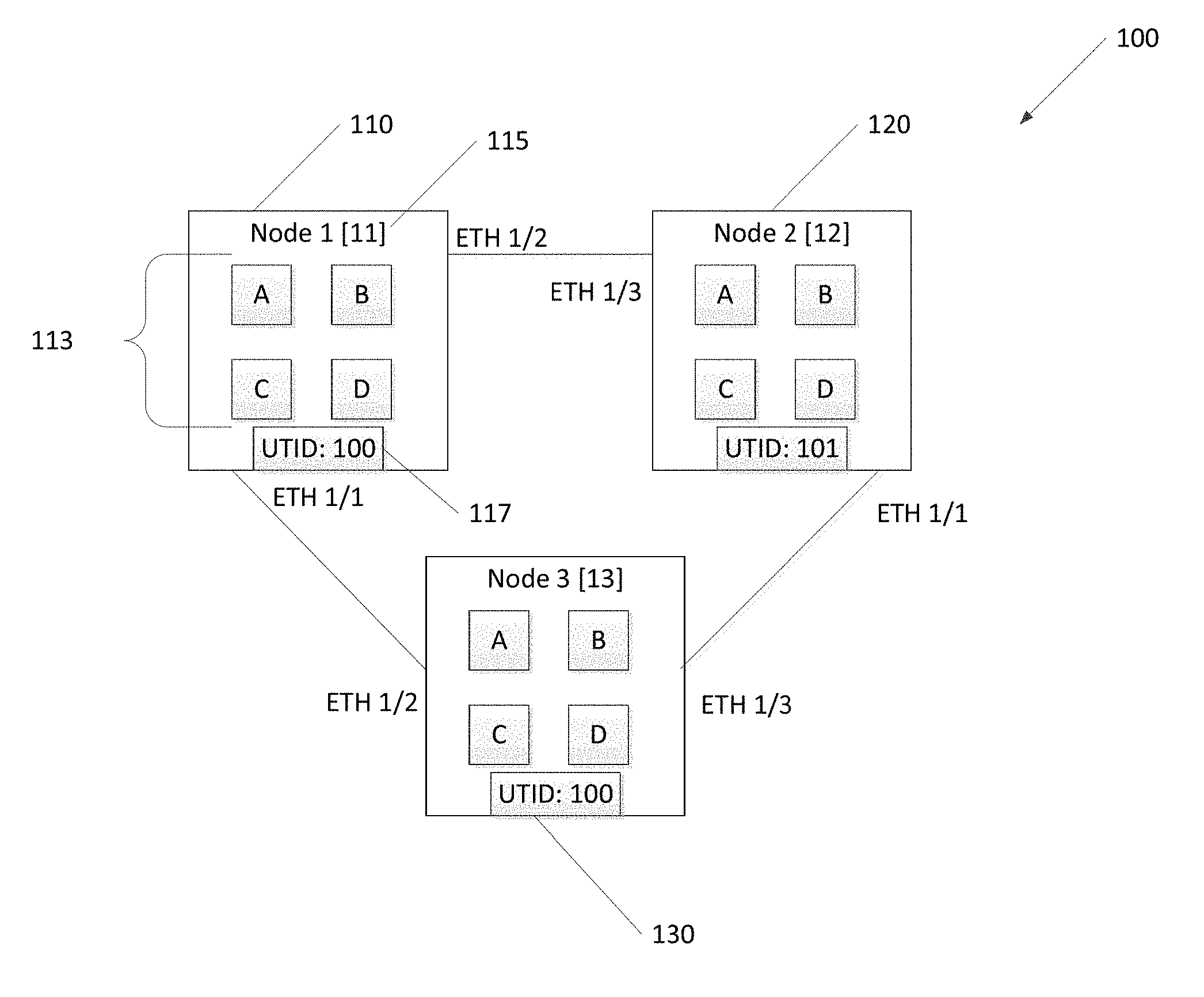
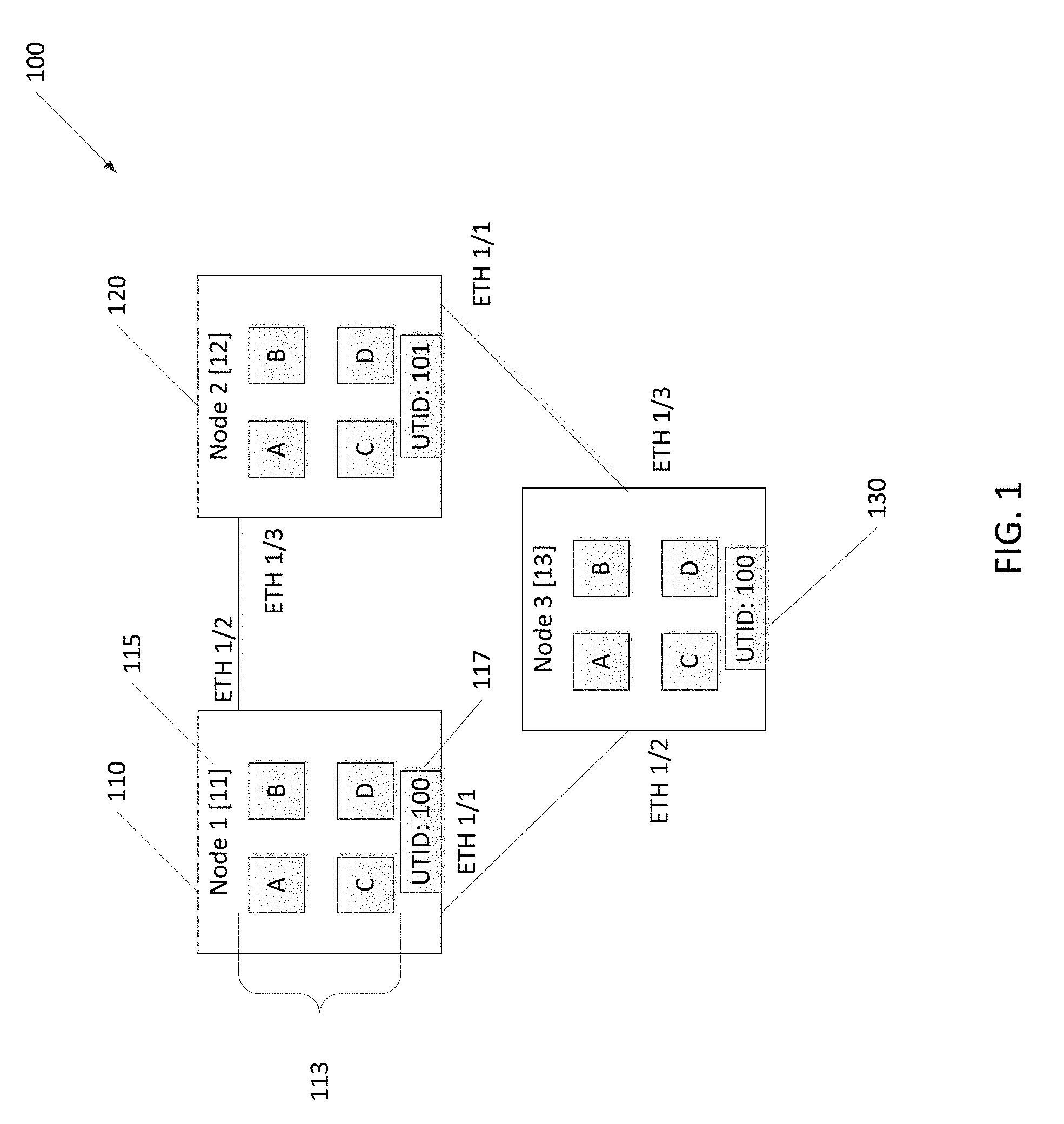
[0015] FIG. 1 illustrates an exemplary switch topology consistent with embodiments of the present disclosure in which an example is provided. Fabric 100 comprises three nodes: node 1 110; node 2 120; and node 3 130. The nodes happen to be connected as a ring, but any other topology is contemplated by this disclosure. The nodes are connected to each other via Ethernet. Each node, 110, 120, and 130, include a counter that counts up and serves to provide a unique UTID for that particular node. In this example the next transaction at node 1 110 will have UTID 100; the next transaction at node 2 120 will have UTID 101; and, the next transaction at node 3 130 will have UTID 100. Each node is also assigned a UFID that is unique to the fabric. Node 1 110 is assigned UFID 11; node 2 120 is assigned UFID 12; and node 3 130 is assigned UFID 13. Each node is running four applications, A, B, C, D, where these applications are not necessarily the same on all nodes.
[0016] Examining fabric 100 under the following scenario yields the following results. A VLAN 12 is created by a user on all three nodes 110, 120, and 130. Then, the user does a shutdown of VLAN 12 on node 2 120.
On Node 2:
[0017] The request is propagated by the back end of a user function, such as VSH to the VLAN Manager. The VLAN Manager shuts down VLAN 12 on node 2 120 and generates a message with a header including UTID: 101; UFID 12. All messages, or transactions, will be tagged with the [101,12] in the header. Due to this transaction, spanning tree protocol ("STP") will put VLAN 12 to disabled on port 1/3 and 1/1. It will send control packets with that information to node 1 110 and node 3 130. The time and the application that sent that control packet is tracked on that port.
On Node 3:
[0018] The BPDU packet, or control packet, is received on port 1/3. Node 3 130 knows that the BPDU packet was received on a port connected with node 1 110 with UFID 13; therefore, the UFID for this packet is 13. The MTS header detail will be UTID 100; UFID 13. All transactions relating to node 3 will be tagged [100, 13].
On Node 1:
[0019] The BPDU packet, or control packet, is received on port 1/2. Node 2 120 knows that the BPDU packet was received on a port connected with node 1 110 with UFID 11; therefore, the UFID for this packet is 11. The MTS header detail will be UTID 100; UFID 11. All transactions relating to node 1 will be tagged [100, 11].
[0020] For the system to work in the best possible fashion, the timestamps between all nodes should be in sync.
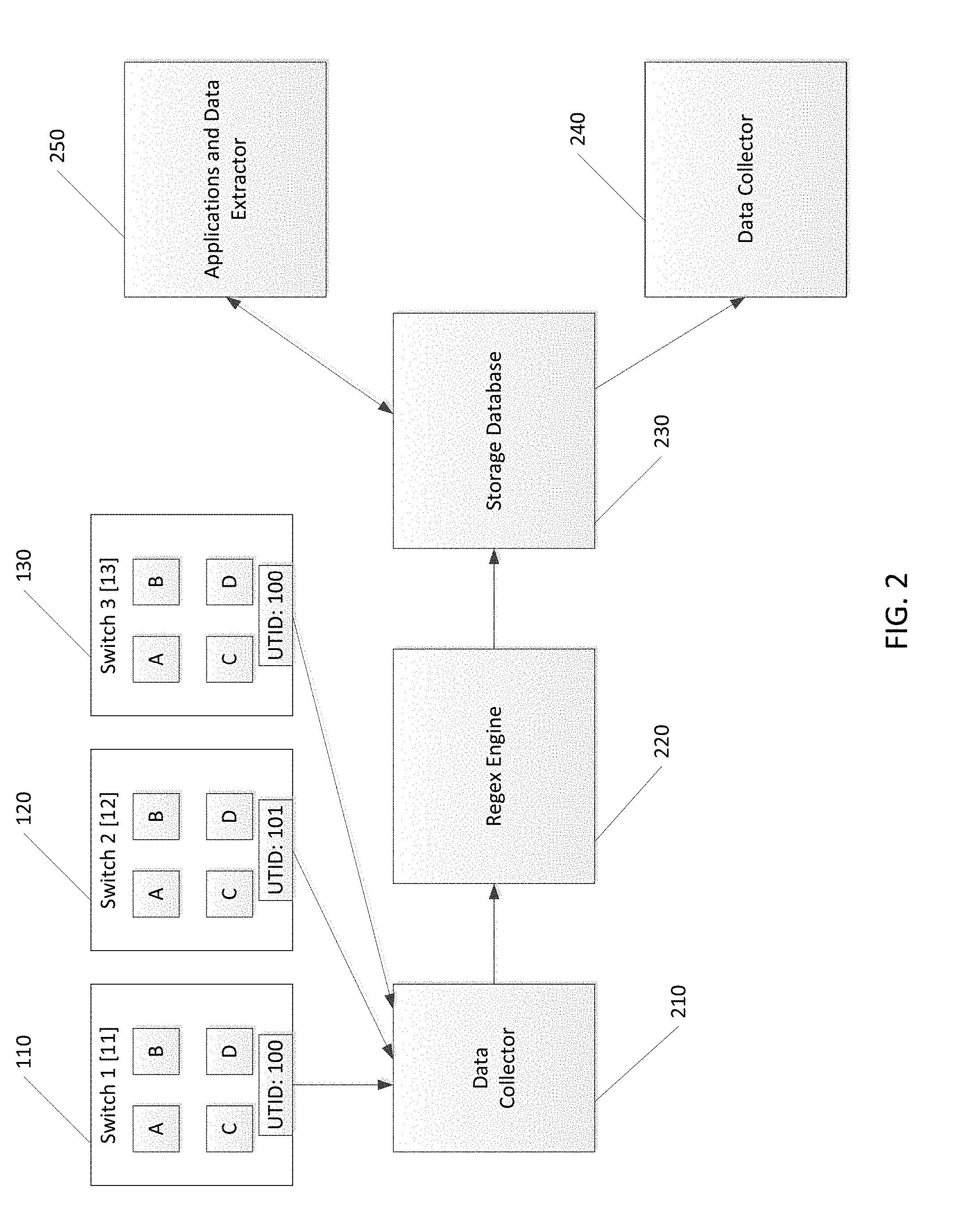
[0021] FIG. 2 illustrates an exemplary message tracking system consistent with embodiments of the present disclosure. The nodes of the fabric, in this example, node 1 110, node 2, 120, and node 3 130, are in communication with a data collector 210 that may be an application running on each node or running on a different node. It collects device data in a non-intrusive manner by evaluating the state of the system, prior to exporting it to a global data store. An application can push data with appropriate meta-data to this agent for publishing it to a user community.
[0022] The data collector(s) 210 are in communication with a Regex Engine 220. The RegEx Engine 220 may take messages in a diverse array of formats and place them into a common format, such as by using key-value pairs. The Regex Engine 220 may be a list of regex. Each regex may extract useful and necessary data to support various data models. The datalogs in the form of file or byte stream data is given as input to the regex engine. The input is made to run against each of the regex and the output obtained has results that populate the various data-models. The output may be a key-value pair pertaining to the data model corresponding to the regex. Users can define custom regex based on the data/log given as input and the data model. The custom regex may then be installed into the RegEx Engine 220 along with the data model.
[0023] The RegEx Engine 220 is in communication with a Storage Database 230, for example, a columnar database, for storing the output of the RegEx Engine 220 which is simply the messages placed into a common format. A data gatherer sits on top of the regex engines and does the writes to the Storage Database 230 and to a Data Collector 240 that may serve to provide notifications to users of certain user-defined changes of state of the Storage Database 230.
[0024] An Applications and Data Extractor 250 is in communication with the Storage Database 230. The Data Extractor is a query engine to extract datasets and transform, modify, aggregate, and/or process queries to feed as input for user-defined queries. The Applications are for user-customizable queries that are created with well-defined templates.
[0025] FIG. 3 is a flow chart of a message tracking process consistent with embodiments of the present disclosure. A new message, or MTS, is generated by a node (stage 310). The current UTID and the UFID of the node, as well as the time, is inserted into the message, or MTS, header (stage 320). The MTS header is carried with the MTS Message throughout the system (stage 330). As the MTS with the header propagates through the fabric, the same function (assigning UTID and UFID) is performed by other nodes in the fabric upon receipt of the MTS with header from the first node (stage 340). The message is placed in a uniform, common format (stage 350), and stored in a database (stage 360). Upon receipt of a query, transactions with similar timestamps are associated with the message (stage 370) and responses to the queries are provided (stage 380).
[0026] Any process, descriptions or blocks in flow charts or flow diagrams should be understood as representing modules, segments, or portions of code which include one or more executable instructions for implementing specific logical functions or steps in the process, and alternate implementations are included within the scope of the present disclosure in which functions may be executed out of order from that shown or discussed, including substantially concurrently or in reverse order, depending on the functionality involved. In some embodiments, steps of processes identified in FIG. 3 using separate boxes can be combined. Further, the various steps in the flow diagrams illustrated in conjunction with the present disclosure are not limited to the architectures described above in association with the description for the flow diagram (as implemented in or by a particular module or logic) nor are the steps limited to the example embodiments described in the specification and associated with the figures of the present disclosure. In some embodiments, one or more steps may be added to the methods described in FIG. 3 either in the beginning, end, and/or as intervening steps, and that in some embodiments, fewer steps may be implemented.
[0027] It should be emphasized that the above-described embodiments of the present disclosure are merely possible examples of implementations, merely set forth for a clear understanding of the principles of the switching systems and methods. Many variations and modifications may be made to the above-described embodiment(s) without departing substantially from the spirit and principles of the disclosure. Although all such modifications and variations are intended to be included herein within the scope of this disclosure and protected by the following claims, the following claims are not necessarily limited to the particular embodiments set out in the description.
* * * * *
D00000
D00001
D00002
D00003
XML
uspto.report is an independent third-party trademark research tool that is not affiliated, endorsed, or sponsored by the United States Patent and Trademark Office (USPTO) or any other governmental organization. The information provided by uspto.report is based on publicly available data at the time of writing and is intended for informational purposes only.
While we strive to provide accurate and up-to-date information, we do not guarantee the accuracy, completeness, reliability, or suitability of the information displayed on this site. The use of this site is at your own risk. Any reliance you place on such information is therefore strictly at your own risk.
All official trademark data, including owner information, should be verified by visiting the official USPTO website at www.uspto.gov. This site is not intended to replace professional legal advice and should not be used as a substitute for consulting with a legal professional who is knowledgeable about trademark law.