Mobile Measurement System for the Three-Dimensional Optical Measurement of Vehicles and Vehicle Parts
BINDEL; Steffen ; et al.
U.S. patent application number 16/150308 was filed with the patent office on 2019-01-31 for mobile measurement system for the three-dimensional optical measurement of vehicles and vehicle parts. The applicant listed for this patent is Bayerische Motoren Werke Aktiengesellschaft. Invention is credited to Steffen BINDEL, Michael HEINZ, Alexander KOENIG, Christopher KURTH.
| Application Number | 20190033063 16/150308 |
| Document ID | / |
| Family ID | 58387817 |
| Filed Date | 2019-01-31 |

| United States Patent Application | 20190033063 |
| Kind Code | A1 |
| BINDEL; Steffen ; et al. | January 31, 2019 |
Mobile Measurement System for the Three-Dimensional Optical Measurement of Vehicles and Vehicle Parts
Abstract
A mobile measurement system for three-dimensional optical measurement of vehicles and vehicle parts, includes a measurement auxiliary device which can be arranged on the vehicle or vehicle part with repeat accuracy, and a mobile measurement trolley on which a robot is arranged, which carries at least one measurement sensor, and which further has a coupling apparatus for mechanically coupling to the measurement auxiliary device, enabling positioning of the measurement trolley relative to the measurement auxiliary device, and thus relative to the vehicle or vehicle part, with repeat accuracy.
| Inventors: | BINDEL; Steffen; (Dresden, DE) ; KOENIG; Alexander; (Rotterode, DE) ; HEINZ; Michael; (Jesewitz, DE) ; KURTH; Christopher; (Landsberg, DE) | ||||||||||
| Applicant: |
|
||||||||||
|---|---|---|---|---|---|---|---|---|---|---|---|
| Family ID: | 58387817 | ||||||||||
| Appl. No.: | 16/150308 | ||||||||||
| Filed: | October 3, 2018 |
Related U.S. Patent Documents
| Application Number | Filing Date | Patent Number | ||
|---|---|---|---|---|
| PCT/EP2017/056605 | Mar 21, 2017 | |||
| 16150308 | ||||
| Current U.S. Class: | 1/1 |
| Current CPC Class: | G01B 11/24 20130101; G01B 5/0025 20130101; G01B 5/0004 20130101 |
| International Class: | G01B 11/24 20060101 G01B011/24; G01B 5/00 20060101 G01B005/00 |
Foreign Application Data
| Date | Code | Application Number |
|---|---|---|
| Apr 4, 2016 | DE | 10 2016 205 519.4 |
Claims
1. A mobile measurement system for three-dimensional optical measurement of vehicles and vehicle parts, comprising: a measurement auxiliary device which is attached in a repeatably accurate manner on the vehicle or vehicle part or on which the vehicle or the vehicle part is arrangeable in a repeatably accurate manner; and a mobile measurement trolley on which a robot, which carries at least one measurement sensor, is arranged and which additionally comprises a coupling device for coupling mechanically with the measurement auxiliary device, as a result of which it is possible to position the measurement trolley in a repeatably accurate manner relative to the measurement auxiliary device and, as a result, relative to the vehicle or the vehicle part.
2. The mobile measurement system as claimed in claim 1, wherein the measurement trolley comprises several ground rollers by way of which the measurement trolley is able to be pushed; and three supporting feet which are extendible via a lifting system and make it possible for the measurement trolley to stand in a three-point support.
3. The mobile measurement system as claimed in claim 1, wherein the measurement auxiliary device comprises several ground rollers by way of which the measurement auxiliary device is able to be pushed, wherein at least one of said ground rollers is provided with a parking brake.
4. The mobile measurement system as claimed in claim 1, wherein the coupling device of the measurement trolley is adjustable in all three directions in space.
5. The mobile measurement system as claimed in claim 1, wherein the coupling device of the measurement trolley comprises several coupling bolts, and the measurement auxiliary device is configured with corresponding coupling bores in which the coupling bolts are able to engage.
6. The mobile measurement system as claimed in claim 5, wherein the coupling bolts are driven by motor such that they are able to engage automatically in the coupling bores.
7. The mobile measurement system as claimed in claim 5, wherein the coupling bores on the measurement auxiliary device are arranged in a grid, whereby different relative positions between the measurement trolley and the measurement auxiliary device are made possible.
8. The mobile measurement system as claimed in claim 6, wherein the coupling bores on the measurement auxiliary device are arranged in a grid, whereby different relative positions between the measurement trolley and the measurement auxiliary device are made possible.
9. The mobile measurement system as claimed in claim 4, wherein the coupling device of the measurement trolley comprises several coupling bolts, and the measurement auxiliary device is configured with corresponding coupling bores in which the coupling bolts are able to engage.
10. The mobile measurement system as claimed in claim 9, wherein the coupling bores on the measurement auxiliary device are arranged in a grid, whereby different relative positions between the measurement trolley and the measurement auxiliary device are made possible.
11. The mobile measurement system as claimed in claim 1, wherein the measurement trolley and/or the measurement auxiliary device comprises at least one pushing aid for manual pushing.
12. The mobile measurement system as claimed in claim 1, wherein the measurement auxiliary device is realized as an L-shaped frame, one frame leg thereof being positioned on a longitudinal side of a vehicle and the other frame leg thereof being positioned on a front or rear side of the vehicle, and separate locator elements, which are fastened or supported on the wheels of the vehicle, are provided for said positioning.
13. The mobile measurement system as claimed in claim 12, wherein the frame legs of the L-shaped frame are connected via a joint so as to be collapsible.
Description
CROSS REFERENCE TO RELATED APPLICATIONS
[0001] This application is a continuation of PCT International Application No. PCT/EP2017/056605, filed Mar. 21, 2017, which claims priority under 35 U.S.C. .sctn. 119 from German Patent Application No. 10 2016 205 519.4, filed Apr. 4, 2016, the entire disclosures of which are herein expressly incorporated by reference.
BACKGROUND AND SUMMARY OF THE INVENTION
[0002] The invention relates to a measurement system for the optical measurement of vehicles and vehicle parts.
[0003] Contactless and, in particular, optical measuring systems have been used for several years in automobile manufacturing for the three-dimensional measurement or measuring of vehicles and vehicle parts. Such systems are disclosed, for example, in DE 10 2004 046 752 B4 and DE 10 2014 106 641 A1. In the case of the disclosed systems, the measuring sensor is moved relative to the measurement object (vehicle or vehicle part) by means of a multi-axis robot or the like. These are stationary systems. Additionally disclosed for simple measurement tasks is arranging the measuring sensor on a mobile or portable stand, for example a stand in the manner shown in DE 10 2008 001 617 A1. However, the problem here is the repeatably accurate positioning with respect to the measurement object. In addition, it is not possible to measure the measurement object in an automated or part-automated manner using this system.
[0004] The object of the invention is to provide a measurement system for the three-dimensional optical measurement of vehicles and vehicle parts which eliminates or at least minimizes one or more disadvantages of the prior art.
[0005] This and other objects are achieved by a mobile measurement system according to the invention for the three-dimensional optical measurement of vehicles and vehicle parts. The mobile measurement system includes:
[0006] at least one measurement auxiliary device which can be attached in a repeatably accurate manner (i.e. with a defined position and alignment) on the vehicle or vehicle part or on which the vehicle or vehicle part can be arranged in a repeatably accurate manner; and
[0007] a mobile measurement trolley on which a robot, which carries at least one measurement sensor or the like, is arranged, wherein said mobile measurement trolley additionally comprises an, in particular adjustable, coupling device for coupling mechanically with the measurement auxiliary device, as a result of which it is possible to position the measurement trolley in a repeatably accurate manner relative to the measurement auxiliary device and, as a result, also relative to the vehicle or vehicle part.
[0008] In a preferred manner, the measurement auxiliary device is only required for positioning and aligning the measurement trolley relative to the measurement object, i.e. to the vehicle or vehicle part, and can then be removed or dismantled again such that it is not able to impair the actual operation of the measurement.
[0009] The measurement system according to the invention comprises a driven robot which, in the usual manner, enables an automated or at least partially automated measurement of the measurement object. In addition, the measurement system according to the invention is realized so as to be mobile or portable and can consequently be used in different locations (measurement sites). Repeatably accurate positioning between the robot and the measurement object (vehicle or vehicle part) works indirectly as a result of the mechanical coupling between the measurement trolley and the measurement auxiliary device. The measurement system according to the invention enables the repeatably accurate positioning of the measurement trolley or of the robot fastened thereon relative to the vehicle (also similar vehicles of a derivative) or vehicle part to be measured which is necessary, in particular, for the automatic measurement operation. The measurement system according to the invention additionally makes it possible to setup and align the measurement system components in a simple, time-saving and ergonomic manner. In addition, in the case of multiple measurement tasks, it is possible to re-position the measurement system components in a simple, rapid and ergonomic manner. There is also a large degree of flexibility as regards different measurement tasks or applications.
[0010] In a preferred manner, the measurement trolley comprises several ground rollers (for example four or five) by way of which the measurement trolley is able to be moved or pushed, and three supporting feet which are extendible by way of a lifting system (in particular with electric drive) and make it possible for the measurement trolley to stand in a fixed, sturdy and tip-resistant manner. As an option, at least one of the ground rollers can also be provided with a parking brake.
[0011] In a preferred manner, the measurement auxiliary device also comprises several ground rollers by way of which the measurement auxiliary device is able to be pushed, wherein in a preferred manner at least one of said ground rollers is provided with a parking brake.
[0012] In a preferred manner, the coupling device of the measurement trolley is adjustable in all three directions in space in order to make possible optimum coupling, which is dependent on the measurement task, with the measurement auxiliary device.
[0013] In a preferred manner, the coupling device of the measurement trolley comprises several, in a preferred manner two, coupling bolts, wherein the measurement auxiliary device is realized with corresponding coupling bores in which the coupling bolts are able to engage in a positive locking manner.
[0014] The coupling bolts on the measurement trolley can be driven by motor (for example by means of an electric motor) such that they are able to engage automatically in the coupling bores on the measurement auxiliary device. As a result, coupling and uncoupling are made easier and the ergonomics are improved.
[0015] The coupling bores on the measurement auxiliary device can be arranged in a grid, as a result of which different, although defined nonetheless, relative positions between the measurement trolley and the measurement auxiliary device are made possible.
[0016] The measurement trolley and/or the measurement auxiliary device can comprise pushing aids or auxiliary devices for manual pushing. These are, for example, handles, grab rods or the like.
[0017] The mobile measurement system according to the invention is used in a preferred manner for measuring or measurement of a vehicle, in particular a passenger vehicle. To this end, the measurement auxiliary device is realized in a preferred manner as an L-shaped frame, the one frame leg thereof being positioned on a longitudinal side of the vehicle and the other frame leg thereof being positioned on the front or rear side of the vehicle. The L-shaped frame makes it possible for the mobile measurement trolley to be able to be positioned in any arbitrary position around the vehicle. A high degree of flexibility and series independence are produced as a result. In a preferred manner, the measurement system according to the invention also includes separate locator elements or spacers which can be fastened or supported in a damage-free manner, for example, on the wheels of the vehicle and which adjust or predetermine a defined and reproducible spacing between the L-shaped frame and the vehicle. In a preferred manner, the frame legs of the frame are connected together in an articulated manner and as a result are collapsible.
[0018] The measurement system according to the invention can also be used for other measurement processes which are not optical, but which measure contactlessly in a similar, in particular equivalent manner.
[0019] Other objects, advantages and novel features of the present invention will become apparent from the following detailed description of one or more preferred embodiments when considered in conjunction with the accompanying drawings.
BRIEF DESCRIPTION OF THE DRAWINGS
[0020] FIG. 1 is a perspective view of a measurement trolley which is associated with the measurement system according to an embodiment of the invention.
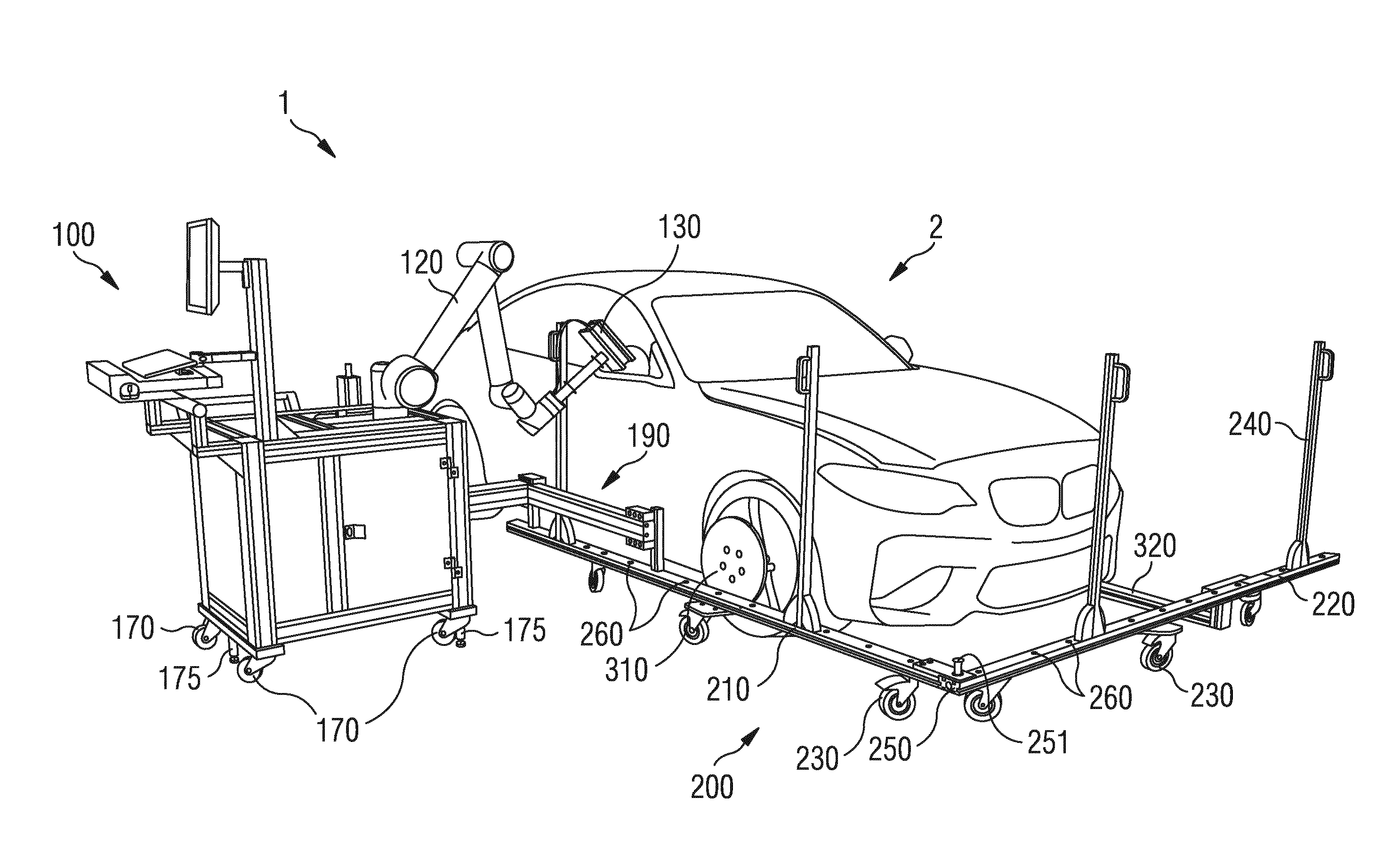
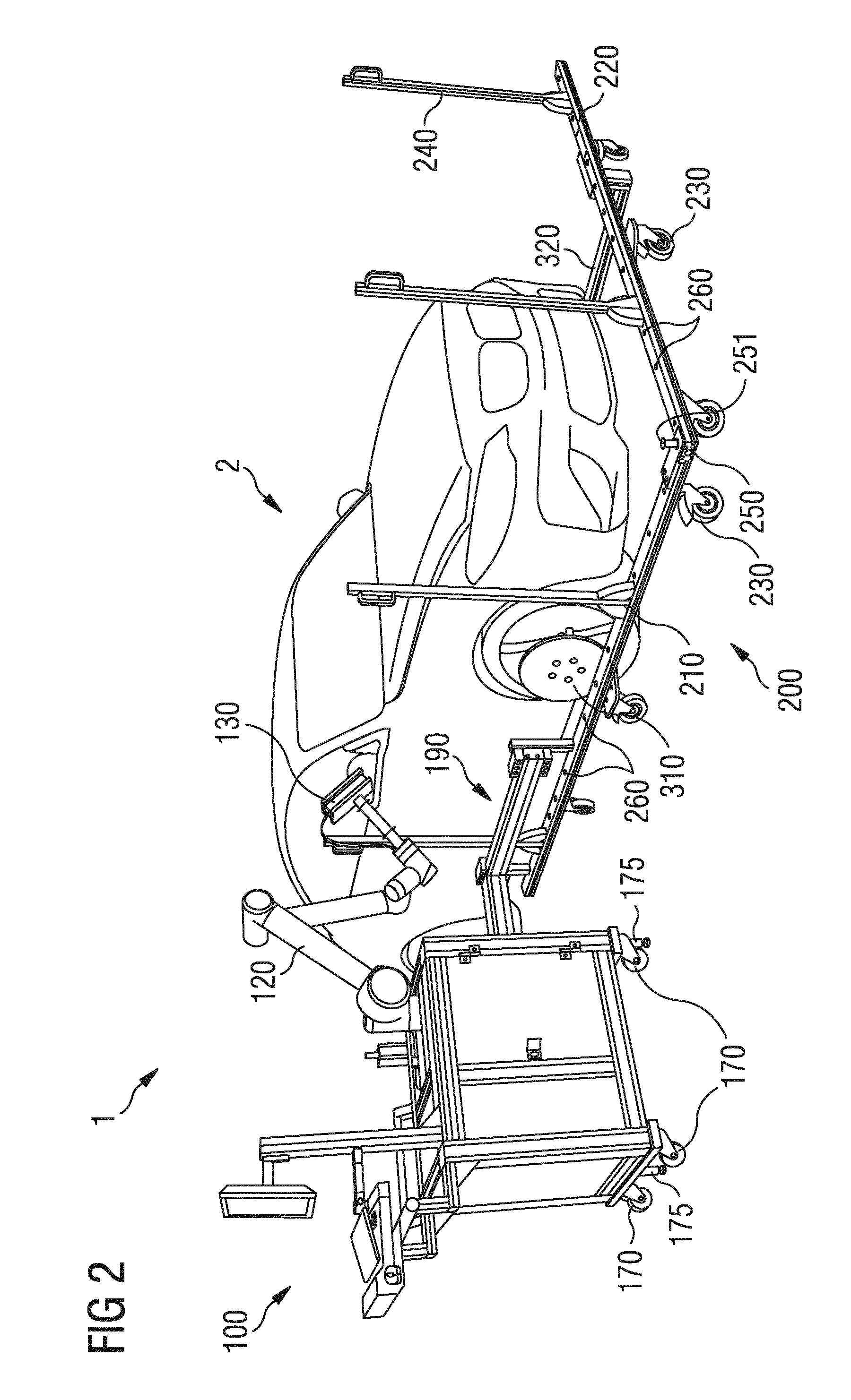
[0021] FIG. 2 is a perspective view of a measurement system according to an embodiment of the invention when measuring a vehicle.
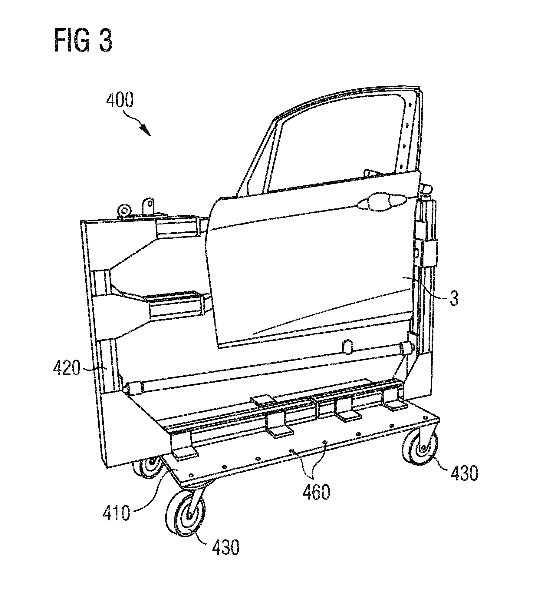
[0022] FIG. 3 is a perspective view of a measurement auxiliary device which is associated with the measurement system according to an embodiment of the invention, with a vehicle door arranged thereon.
DETAILED DESCRIPTION OF THE DRAWINGS
[0023] The measurement trolley 100 shown in FIG. 1 includes a framework 110 which is composed of profiles and on which a light multi-axis robot 120 is fastened. The robot arm of the robot 120 carries a measurement sensor or measurement head 130 for three-dimensional optical measurement of a measurement object. The measurement sensor 130 can be moved by way of the robot 120. The measurement procedure, including the robot arm movements, is controlled by a control device 140, typically a computer, arranged in the interior of the framework 110. Communication with the control device 140 is effected by way of an input device (keyboard and mouse) 150 and a monitor 160. The measurement trolley or robot trolley 100 is realized in a mobile manner, to which end it has several ground rollers (fixed castors) 170 and handles 181 and 182 which function as pushing aids.
[0024] The measurement trolley 100 additionally includes a coupling device 190 which includes two coupling bolts 194. The coupling bolts 194 are fastened on a rail 192 so as to be horizontally displaceable. The rail 192 is fastened on the framework 110 by means of a retractable and extendible carrier 191. The coupling bolts 194 can also be moved vertically by motor-driven actuating mechanisms 193. Consequently, the coupling device 190 is adjustable in all three directions in space, as illustrated by the double arrows. The function of the coupling device 190 will be explained in more detail below.
[0025] FIG. 2 shows a measurement system 1 with a measurement trolley 100 according to FIG. 1 during the measuring or measurement of a vehicle 2. The vehicle 2 and the mobile measurement trolley 100 stand on a floor area, for example a hall floor. In order to enable precise and repeatably accurate positioning of the measurement trolley 100 with respect to the vehicle 2, there is provided a measurement auxiliary device 200 which is associated with the measurement system 1, this being an L-shaped trolley or frame. The frame 200, which is also provided with ground rollers (fixed castors) 230 and as a result is mobile, includes two frame legs 210 and 220 and several grip rods 240 which function as pushing aids. The length of the frame legs 210 and 220, for example, is between 2 m and 4 m. The two frame legs 210 and 220, which are arranged at right angles with respect to one another, are connected via a joint 250 such that the frame 200 is able to be collapsed in a space-saving manner when not in use. The joint 250 comprises a locking mechanism which is able to be released by way of the latching bolt 251.
[0026] In the example shown, one of the frame legs 210 is positioned on the right-hand longitudinal side of the vehicle 2 and the other frame leg 220 is positioned on the front side of the vehicle 2. The correct positioning works by way of a first locator element 310, this being a disk which is fastened magnetically on the wheel screws of the right-hand front wheel of the vehicle 2, and a second locator element 320 which is supported in a chock-like manner on the left-hand front wheel of the vehicle 2 and projects forward beyond the vehicle outline. The two locator elements 310 and 320 form stops against which the frame legs 210 and 220 of the frame 200 can be moved to abut and, in this case, take up a defined spacing from the vehicle 2. In this respect, the locator element 310 and 320 can also be designated as spacers.
[0027] The measurement trolley 100 is mechanically coupled with the frame 200, for which purpose the coupling bolts 194 of the coupling device 190 engage in corresponding coupling bores 260 in the frame leg 210. As a result of the positive locking closure, the measurement trolley 100 is aligned relative to the frame 200, and as a result relative to the vehicle 2. Both frame legs 210 and 220 of the measurement auxiliary device 200 are realized with a plurality of coupling bores 260 which are arranged in a grid (for example a 100 mm grid). The measurement trolley 100 can consequently also assume a different relative position with respect to the frame 200, in dependence on the measurement task, or can be coupled with the frame 200 at a different position.
[0028] The measurement system 1 is mobile and can be used in any location. The components of the measurement system 1 are set up at the place of measurement, for example in the arrangement shown in FIG. 2, as explained in more detail below, and are dismantled again on completion of the measurement. Simple and ergonomic handling is made possible in this case. If the same vehicle 2 or the same vehicle model is to be measured again subsequently, the system components are able to be set up again in the same arrangement, even at a different location, repeatably accurate positioning of the measurement trolley 100 with respect to the vehicle 2 being made possible within the necessary tolerance (this is typically in the centimeter range). In addition, the power can be supplied by a power pack which is arranged in the measurement trolley 100 such that the measurement system 1 is also operable independently of an external power supply.
[0029] To set up the measurement system 1, the locator elements 310 and 320 are first of all arranged on the vehicle 2. The frame or L-shaped trolley 200 is then aligned with the locator elements 310 and 320 and fixed as a result of locking the ground rollers 230. The measurement trolley 100 can then be coupled with the frame 200 in a desired position or in a position determined by earlier measurements, to which end said measurement trolley is positioned relative to the frame 200, the coupling unit 190 is adjusted and the coupling bolts 194 are lowered by way of the actuating mechanisms 193 such that they engage in a positive locking manner in the corresponding coupling bores 260 of the frame 200.
[0030] The extendible carrier 191 and the bearing rail 192 of the coupling unit 190 are provided with graduations which enable the restoring of a specific setting. In addition, the bores 260 are numbered on the frame 200 in order to enable the restoring of a specific engagement pairing. Once the measurement trolley 100 is correctly positioned, it is locked as a result of extending three supporting feet 175, which enable a tip-resistant 3-point base. As an option, only the frame 200 and the locator elements 310 and 320 can be removed again so that they do not impair the measurement. Where applicable, reference marks or the like are also applied to the vehicle 2 to be measured. The measurement can then be started, to which end, for example, the robot 120 or the robot arm thereof with the measurement head 130 fastened thereon can be manually controlled via the input device 150 or a previously generated measurement program is started. (The measurement system 1 according to the invention makes it possible to run stored measurement programs for the relevant vehicle model or a similar vehicle model in a safe manner automatically as the always same positioning of the L-shaped trolley 200 with respect to the vehicle 2 ensures the repeatably accurate positioning and alignment of the measurement trolley 100 relative to the vehicle 2). In a preferred manner, the evaluation of the measurement is also taken over by the control device 140. Further measurements can also be performed on the vehicle 2, to which end it is also possible to re-position the measurement trolley 100 and/or the frame 200 where applicable.
[0031] FIG. 3 shows a different measurement auxiliary device 400 which includes a base plate 410 and a framework 420 on which a vehicle part 3 to be measured (a vehicle door as an example) is fastened. The measurement auxiliary device 400 additionally has lockable ground rollers 430. The base plate 410 is realized with a plurality of coupling bores 460 which are arranged in a grid. Analogously to the previous explanations, the measurement trolley 100 can be aligned relative to the measurement auxiliary device 400 and as a result relative to the vehicle part 3 as a result of engagement of the coupling bolts 194 in the coupling bores 460. One assembly or an entire vehicle 2 can also be arranged on such a measurement auxiliary device 400.
LIST OF REFERENCES
[0032] 1 Measurement system [0033] 2 Vehicle [0034] 3 Vehicle part [0035] 100 Measurement trolley [0036] 110 Framework [0037] 120 Robot [0038] 130 Measurement sensor [0039] 140 Control device [0040] 150 Input device [0041] 160 Monitor [0042] 170 Ground roller [0043] 175 Supporting foot [0044] 181 Handle [0045] 182 Handle [0046] 190 Coupling device [0047] 191 Carrier [0048] 192 Rail [0049] 193 Actuating mechanism [0050] 194 Coupling bolt [0051] 200 Measurement auxiliary device [0052] 210 Frame leg [0053] 220 Frame leg [0054] 230 Ground roller [0055] 240 Grab rod [0056] 250 Joint [0057] 251 Latching bolt [0058] 260 Coupling bolt [0059] 310 Locator element [0060] 320 Locator element [0061] 400 Measurement auxiliary device [0062] 410 Base plate [0063] 420 Framework [0064] 430 Ground roller [0065] 460 Coupling bores
[0066] The foregoing disclosure has been set forth merely to illustrate the invention and is not intended to be limiting. Since modifications of the disclosed embodiments incorporating the spirit and substance of the invention may occur to persons skilled in the art, the invention should be construed to include everything within the scope of the appended claims and equivalents thereof.
* * * * *
D00000
D00001
D00002
D00003
XML
uspto.report is an independent third-party trademark research tool that is not affiliated, endorsed, or sponsored by the United States Patent and Trademark Office (USPTO) or any other governmental organization. The information provided by uspto.report is based on publicly available data at the time of writing and is intended for informational purposes only.
While we strive to provide accurate and up-to-date information, we do not guarantee the accuracy, completeness, reliability, or suitability of the information displayed on this site. The use of this site is at your own risk. Any reliance you place on such information is therefore strictly at your own risk.
All official trademark data, including owner information, should be verified by visiting the official USPTO website at www.uspto.gov. This site is not intended to replace professional legal advice and should not be used as a substitute for consulting with a legal professional who is knowledgeable about trademark law.