Refrigerator Appliances Including A Drawer Assembly
Wantland; Louis A. ; et al.
U.S. patent application number 15/663902 was filed with the patent office on 2019-01-31 for refrigerator appliances including a drawer assembly. The applicant listed for this patent is Haier US Appliance Solutions, Inc.. Invention is credited to Bagawathkumar Chellappan, Louis A. Wantland.
| Application Number | 20190032993 15/663902 |
| Document ID | / |
| Family ID | 65037793 |
| Filed Date | 2019-01-31 |


| United States Patent Application | 20190032993 |
| Kind Code | A1 |
| Wantland; Louis A. ; et al. | January 31, 2019 |
REFRIGERATOR APPLIANCES INCLUDING A DRAWER ASSEMBLY
Abstract
Refrigerator appliances that include a drawer assembly are provided herein. The drawer assembly may generally include a primary door and secondary door. The primary door may be slidably mounted to a cabinet of the refrigerator appliance to selectively move along a transverse direction between a primary open position permitting access to a chamber and a primary closed position restricting access to the chamber. The primary door may define a secondary opening. The secondary door may extend in a lateral direction from along at least a portion of the primary door. The secondary door may be movably mounted to the primary door to selectively move between a secondary open position permitting access to the chamber through the secondary opening and a secondary closed position restricting access through the secondary opening.
| Inventors: | Wantland; Louis A.; (Louisville, KY) ; Chellappan; Bagawathkumar; (Prospect, KY) | ||||||||||
| Applicant: |
|
||||||||||
|---|---|---|---|---|---|---|---|---|---|---|---|
| Family ID: | 65037793 | ||||||||||
| Appl. No.: | 15/663902 | ||||||||||
| Filed: | July 31, 2017 |
| Current U.S. Class: | 1/1 |
| Current CPC Class: | F25D 25/025 20130101; F25D 23/025 20130101; F25D 21/04 20130101; F25D 11/02 20130101; F25D 23/028 20130101 |
| International Class: | F25D 25/02 20060101 F25D025/02; F25D 11/02 20060101 F25D011/02; F25D 23/02 20060101 F25D023/02; F25D 21/04 20060101 F25D021/04 |
Claims
1. A refrigerator appliance defining a vertical direction, a lateral direction, and a transverse direction, the vertical, lateral, and transverse directions being mutually perpendicular, the refrigerator appliance comprising: a cabinet defining a fresh food chamber for receipt of fresh food articles and a freezer chamber for receipt of frozen food articles; and a freezer drawer assembly comprising a primary door extending in the lateral direction from a first side to a second side, the primary door being slidably mounted to the cabinet to selectively move along the transverse direction between a primary open position permitting access to the freezer chamber and a primary closed position restricting access to the freezer chamber, the primary door defining a secondary opening, and a secondary door extending in the lateral direction from the first side to the second side, the secondary door being movably mounted to the primary door to selectively move between a secondary open position permitting access to the freezer chamber through the secondary opening and a secondary closed position restricting access to the secondary opening.
2. The refrigerator appliance of claim 1, wherein the freezer drawer assembly further comprises a handle mounted to the secondary door to move the primary door between the primary open position and the primary closed position.
3. The refrigerator appliance of claim 2, wherein the freezer drawer assembly further comprises a locking assembly selectively securing the secondary door in the secondary closed position.
4. The refrigerator appliance of claim 3, wherein the locking assembly comprises a catch comprising a body mounted to the primary door, the body comprising a support surface and a locking member, the support surface positioned between the outer surface of the inner door and the inner surface of the outer door along the transverse direction, and a latch coupled to the outer door, the latch operable to engage the locking member.
5. The refrigerator appliance of claim 4, wherein the secondary door is pivotally mounted to the primary door and defines a rotation axis parallel to the lateral direction.
6. The refrigerator appliance of claim 1, wherein the freezer drawer assembly further comprises a top basket slidably mounted to the cabinet independent of the primary door to selectively extend through the secondary opening.
7. The refrigerator appliance of claim 6, wherein the freezer drawer assembly further comprises a bottom basket positioned below the top basket along the vertical direction.
8. The refrigerator appliance of claim 6, wherein the secondary door comprises a presentation latch selectively engaged with the top basket to motivate the top basket through the secondary opening.
9. The refrigerator appliance of claim 1, wherein the freezer drawer assembly further comprises a secondary gasket attached to the secondary door to contact the primary door along a mated surface in the secondary closed position.
10. The refrigerator appliance of claim 9, wherein the freezer drawer assembly further comprises a heater positioned on the primary door along the mated surface.
11. A refrigerator appliance defining a vertical direction, a lateral direction, and a transverse direction, the vertical, lateral, and transverse directions being mutually perpendicular, the refrigerator appliance comprising: a cabinet defining a fresh food chamber for receipt of fresh food articles and a freezer chamber for receipt of frozen food articles, the freezer chamber being positioned below the fresh food chamber along the vertical direction; and a freezer drawer assembly comprising a primary door slidably mounted to the cabinet to selectively move along the transverse direction between a primary open position permitting access to the freezer chamber and a primary closed position restricting access to the freezer chamber, the primary door defining a secondary opening, a secondary door extending in the lateral direction along at least a portion of the primary door, the secondary door being movably mounted to the primary door to selectively move between a secondary open position permitting access to the freezer chamber through the secondary opening and a secondary closed position restricting access through the secondary opening, and a handle mounted to the secondary door and comprising a locking assembly selectively securing the secondary door in the secondary closed position to move the primary door between the primary open position and the primary closed position.
12. The refrigerator appliance of claim 11, wherein the locking assembly comprises a catch comprising a body mounted to the primary door, the body comprising a support surface and a locking member, the support surface positioned between the outer surface of the inner door and the inner surface of the outer door along the transverse direction, and a latch coupled to the outer door, the latch operable to engage the locking member.
13. The refrigerator appliance of claim 11, wherein the secondary door is pivotally mounted to the primary door and defines a rotation axis parallel to the lateral direction.
14. The refrigerator appliance of claim 11, wherein the freezer drawer assembly further comprises a top basket slidably mounted to the cabinet independent of the primary door to selectively extend through the secondary opening.
15. The refrigerator appliance of claim 14, wherein the freezer drawer assembly further comprises a bottom basket positioned below the top basket along the vertical direction.
16. The refrigerator appliance of claim 14, wherein the secondary door comprises a presentation latch selectively engaged with the top basket to motivate the top basket through the secondary opening.
17. The refrigerator appliance of claim 11, wherein the freezer drawer assembly further comprises a secondary gasket attached to the secondary door to contact the primary door along a mated surface in the secondary closed position.
18. The refrigerator appliance of claim 17, wherein the freezer drawer assembly further comprises a heater positioned on the primary door along the mated surface.
Description
FIELD OF THE INVENTION
[0001] The present subject matter relates generally to refrigerator appliances, and more particularly to refrigerator having a drawer assembly for, as an example, a freezer chamber.
BACKGROUND OF THE INVENTION
[0002] Refrigerator appliances generally include a cabinet that defines one or more chilled chambers for the receipt and storage of food items. Certain refrigerator appliances include a fresh food chamber for storage of food items above the freezing temperature of water and a freezer chamber for storage of food items below the freezing temperature of water. The fresh food chamber and the freezer chamber can be positioned at various locations relative to each other within the cabinet. Consumers generally prefer chilled chambers that facilitate visibility and accessibility of food items stored therein. However, the arrangement of the fresh food chamber and the freezer chamber within a refrigerator appliance's cabinet can affect food items' visibility and accessibility.
[0003] In certain refrigerator appliances, commonly referred to as side-by-side style refrigerator appliances, the fresh food chamber is positioned next to the freezer chamber within the cabinet. Such a configuration can permit easy access to food items stored on doors of the refrigerator appliances. However, the cabinet can be deep and narrow such that accessing food items at a back of the fresh food chamber and/or freezer chamber can be difficult.
[0004] In other refrigerator appliances, commonly referred to as bottom mount refrigerator appliances, the freezer chamber is positioned below the fresh food chamber in the cabinet. Such a configuration can provide a wide fresh food chamber and/or a wide freezer chamber. However, bottom freezer configurations typically rely on one or two large sliding bins where food items are placed. Smaller food items can sometimes be lost or difficult to access when placed among many larger items. For example, smaller items tend to fall to the bottom of the bins, such that larger items must first be removed before reaching the small items. Moreover, opening the freezer door to find frequently accessed food items can result in significant energy losses.
[0005] In addition, some freezer chambers may include multiple drawers attached to separate doors to allow selective access to portions of the freezer chamber. However, insulating mullions or walls are typically required to prevent heat transfer. Such configurations may reduce the amount of available storage, hinder visibility into the freezer chamber, and/or restrict the size of items that may be received within the freezer chamber.
[0006] Accordingly, a refrigerator having a bottom freezer with improved accessibility would be useful. Further, a freezer door that allows for quicker access to frequently used items, improved visibility and access would be particularly beneficial.
BRIEF DESCRIPTION OF THE INVENTION
[0007] Aspects and advantages of the invention will be set forth in part in the following description, or may be obvious from the description, or may be learned through practice of the invention.
[0008] In one aspect of the present disclosure, a refrigerator appliance is provided. The refrigerator appliance may include a cabinet defining a fresh food chamber for receipt of fresh food articles and a freezer chamber for receipt of frozen food articles, and a freezer drawer assembly. The freezer drawer assembly may include a primary door and a secondary door. The primary door may extend in a lateral direction from a first side to a second side. The primary door may be slidably mounted to the cabinet to selectively move along a transverse direction between a primary open position permitting access to the freezer chamber and a primary closed position restricting access to the freezer chamber. The primary door may further define a secondary opening. The secondary door may extend in the lateral direction from the first side to the second side. The secondary door may be movably mounted to the primary door to selectively move between a secondary open position permitting access to the freezer chamber through the secondary opening and a secondary closed position restricting access to the secondary opening.
[0009] In another aspect of the present disclosure, a refrigerator appliance is provided. The refrigerator appliance may include a cabinet defining a fresh food chamber for receipt of fresh food articles and a freezer chamber for receipt of frozen food articles, and a freezer drawer assembly. The freezer drawer assembly may include a primary door, a secondary door, and a handle. The primary door may be slidably mounted to the cabinet to selectively move along a transverse direction between a primary open position permitting access to the freezer chamber and a primary closed position restricting access to the freezer chamber. The primary door may define a secondary opening. The secondary door may extend in a lateral direction from along at least a portion of the primary door. The secondary door may be movably mounted to the primary door to selectively move between a secondary open position permitting access to the freezer chamber through the secondary opening and a secondary closed position restricting access through the secondary opening. The handle may be mounted to the secondary door and comprising a locking assembly selectively securing the secondary door in the secondary closed position to move the primary door between the primary open position and the primary closed position.
[0010] These and other features, aspects and advantages of the present invention will become better understood with reference to the following description and appended claims. The accompanying drawings, which are incorporated in and constitute a part of this specification, illustrate embodiments of the invention and, together with the description, serve to explain the principles of the invention.
BRIEF DESCRIPTION OF THE DRAWINGS
[0011] A full and enabling disclosure of the present invention, including the best mode thereof, directed to one of ordinary skill in the art, is set forth in the specification, which makes reference to the appended figures.
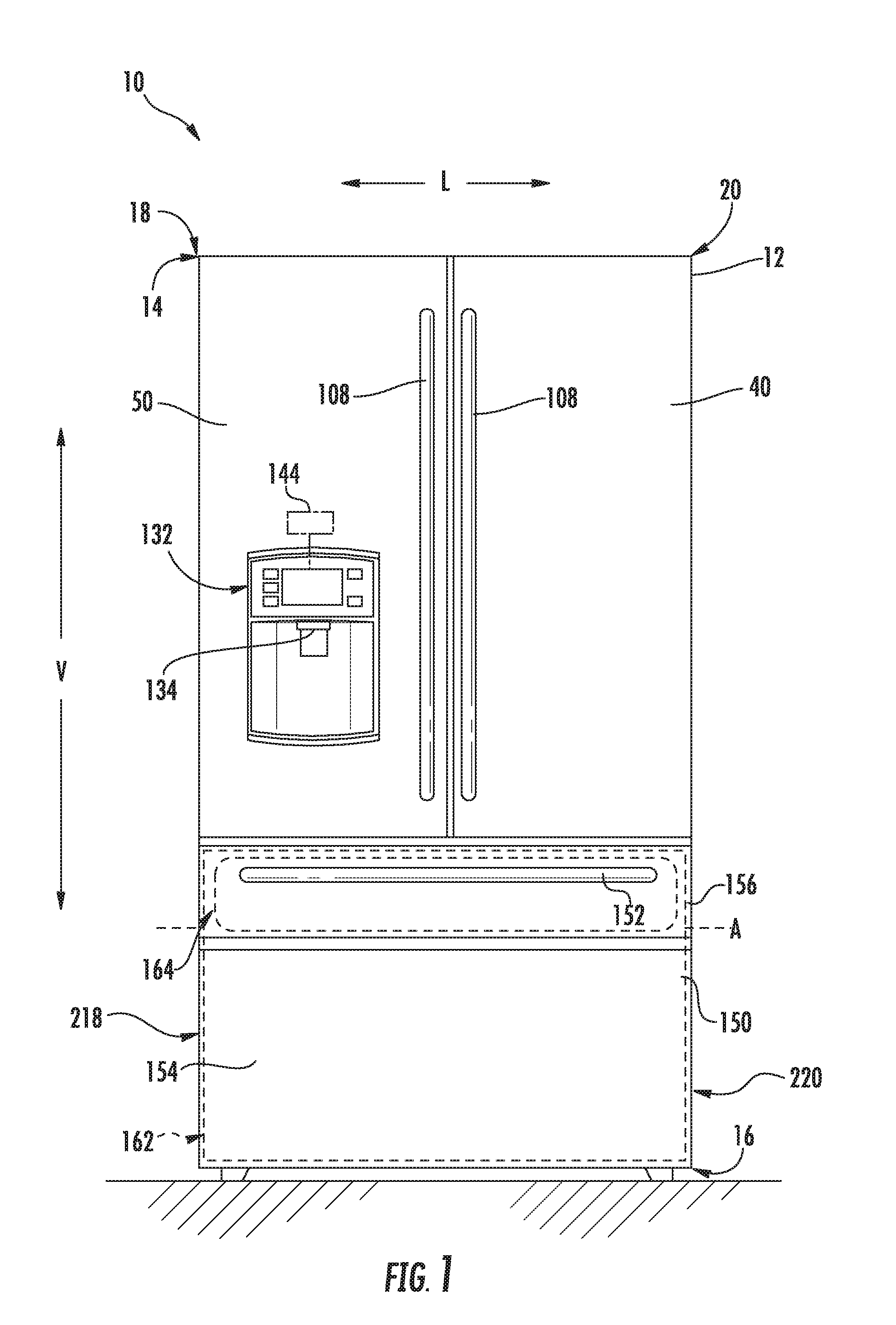
[0012] FIG. 1 provides a front elevation view of a refrigerator appliance according to exemplary embodiments of the present disclosure.
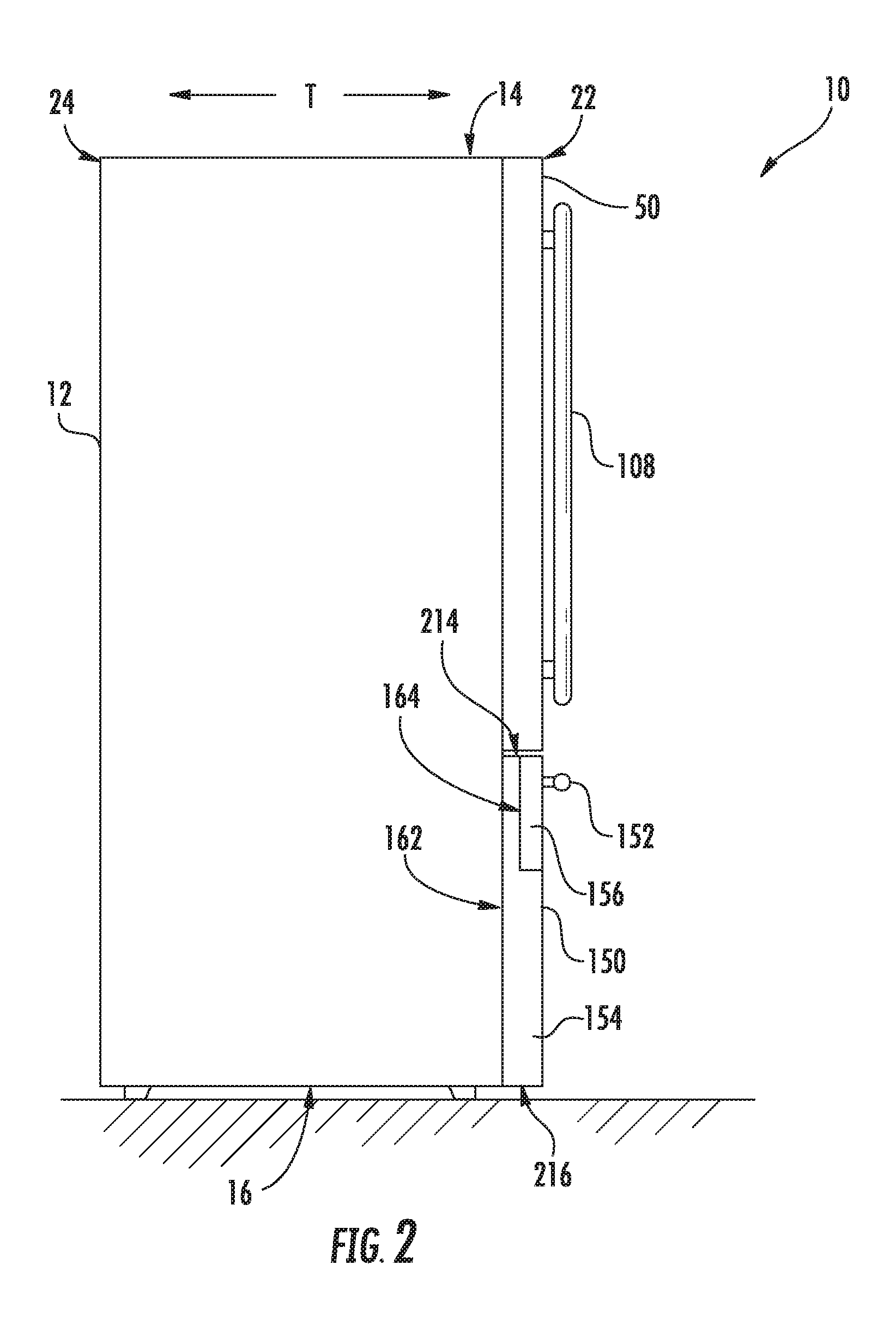
[0013] FIG. 2 provides a side view of the exemplary refrigerator appliance of FIG. 1.
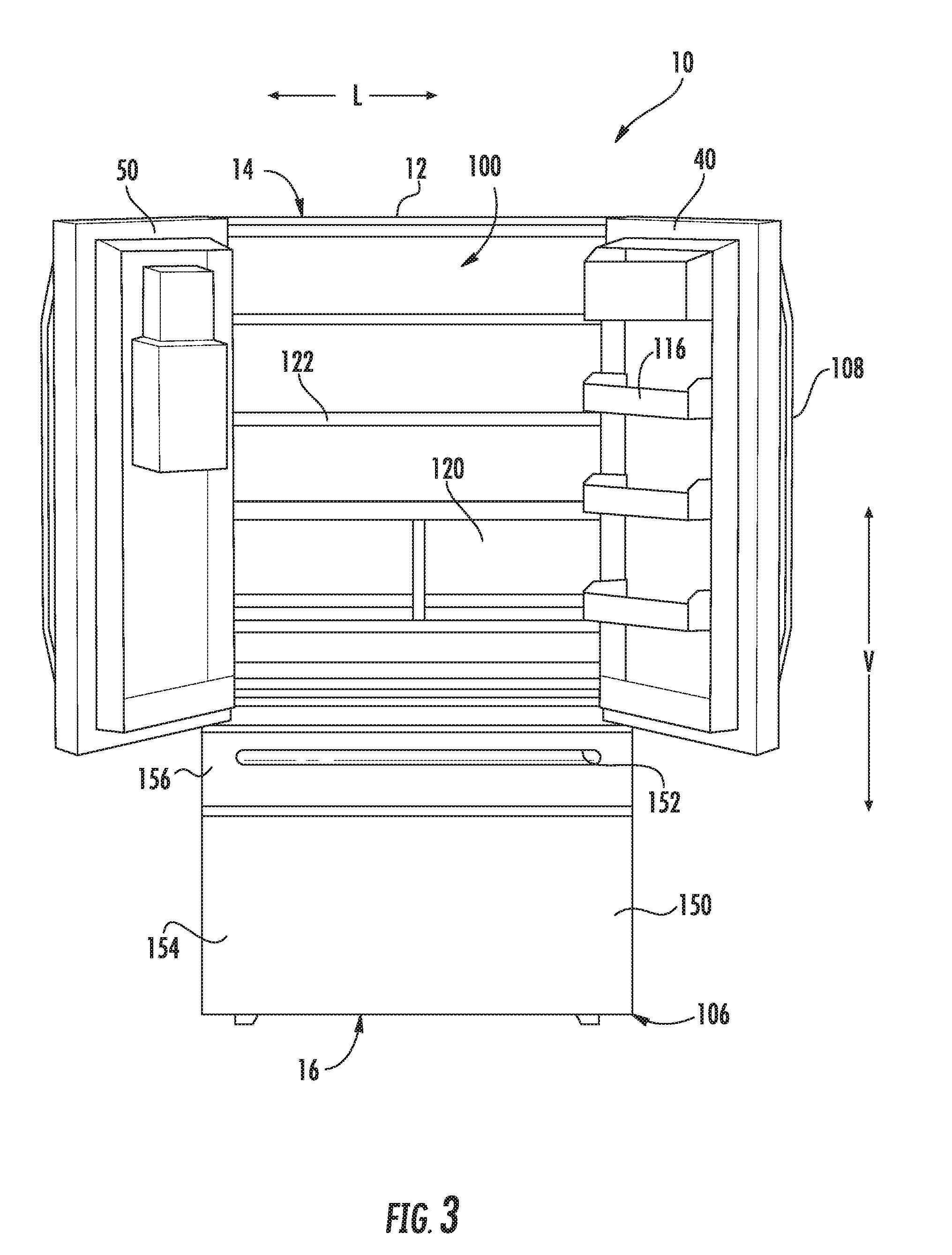
[0014] FIG. 3 provides a front perspective view of the exemplary refrigerator appliance of FIG. 1 with the refrigerator doors shown in an open position.
[0015] FIG. 4 is a side schematic view of a refrigerator appliance according to exemplary embodiments of the present disclosure, wherein a primary door is extended in a primary open position.
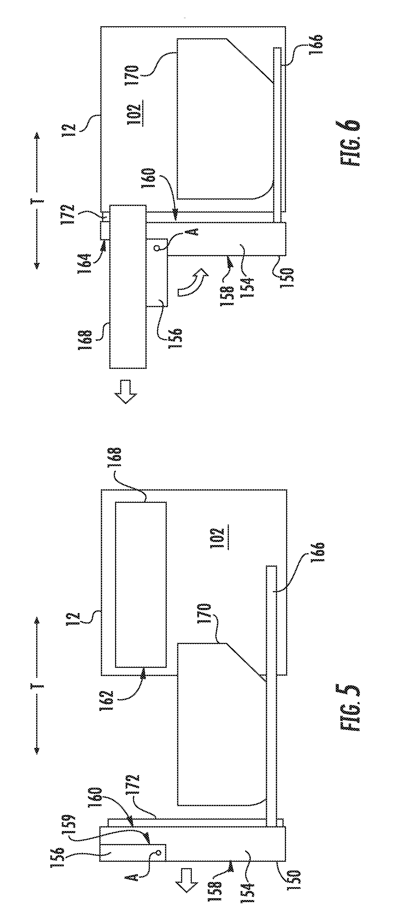
[0016] FIG. 5 is a side schematic view of the freezer chamber of the refrigerator appliance of FIG. 4 with a primary door in a primary open position.
[0017] FIG. 6 is a side schematic view of the freezer chamber of the refrigerator appliance of FIG. 4 with a secondary door in a secondary open position.
[0018] FIG. 7 is a side schematic view of the freezer chamber of the refrigerator appliance of FIG. 4 with a secondary door in a secondary open position, including a magnified view of a presentation latch engaged with a top basket.
[0019] FIG. 8 is a side schematic view of a freezer chamber of the refrigerator appliance of FIG. 4 according to further exemplary embodiments of the present disclosure.
[0020] FIG. 9 is a magnified perspective view of a portion of a primary door and secondary door, including a locking assembly, of a refrigerator appliance according to exemplary embodiments of the present disclosure.
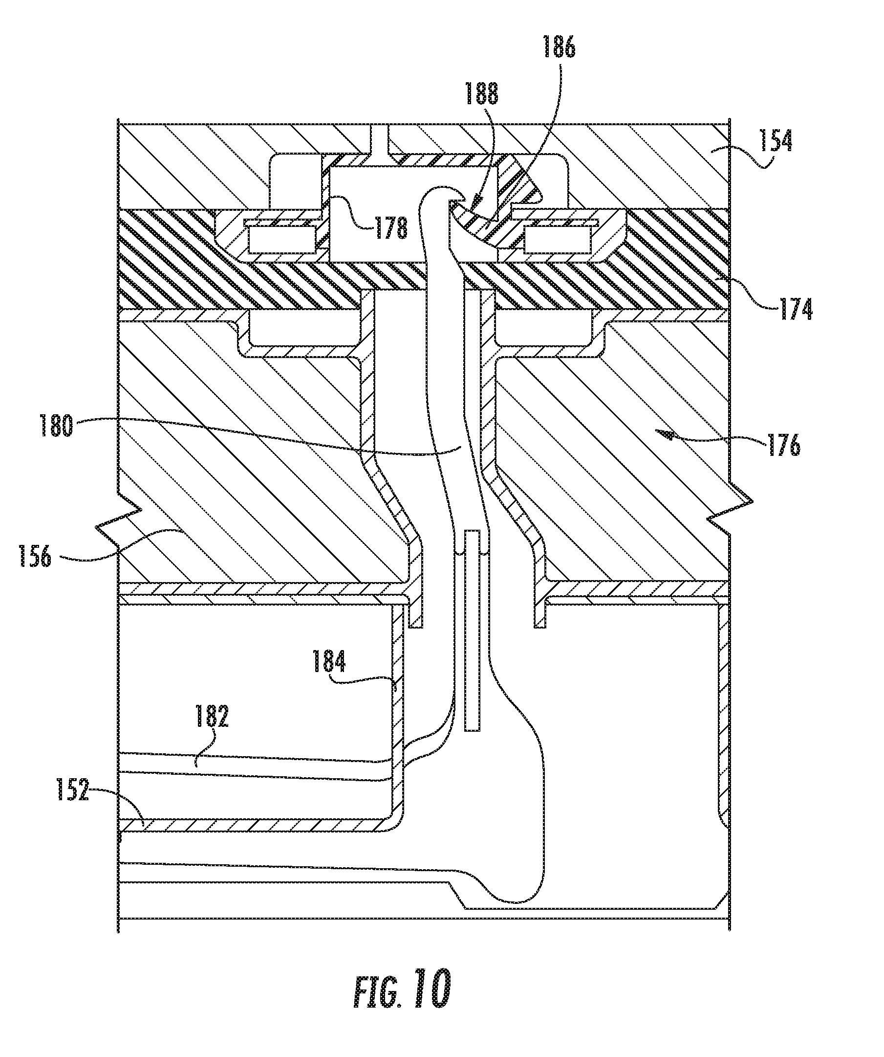
[0021] FIG. 10 provides a cross-sectional view of a locking assembly, wherein a latch of the locking assembly is attached to a catch of the locking assembly.
DETAILED DESCRIPTION
[0022] Reference now will be made in detail to embodiments of the invention, one or more examples of which are illustrated in the drawings. Each example is provided by way of explanation of the invention, not limitation of the invention. In fact, it will be apparent to those skilled in the art that various modifications and variations can be made in the present invention without departing from the scope or spirit of the invention. For instance, features illustrated or described as part of one embodiment can be used with another embodiment to yield a still further embodiment. Thus, it is intended that the present invention covers such modifications and variations as come within the scope of the appended claims and their equivalents.
[0023] As used herein, the terms "first," "second," and "third" may be used interchangeably to distinguish one component from another and are not intended to signify location or importance of the individual components. Terms such as "inner" and "outer" refer to relative directions with respect to the interior and exterior of the refrigerator appliance, and in particular the food storage chamber(s) defined therein. For example, "inner" or "inward" refers to the direction towards the interior of the refrigerator appliance. Terms such as "left," "right," "front," "back," "top," or "bottom" are used with reference to the perspective of a user accessing the refrigerator appliance. For example, a user stands in front of the refrigerator to open the doors and reaches into the food storage chamber(s) to access items therein.
[0024] Generally, the present disclosure may provide a refrigerator appliance that has a freezer drawer assembly. The freezer drawer assembly may include a primary door that can slide to open or close over a primary opening to the freezer chamber. A secondary door may also be attached to the primary door to open or close a secondary opening in the primary door. In turn, the secondary door can be opened to permit access to the freezer chamber without opening the primary door.
[0025] Turning now to the figures, FIGS. 1 through 3 provide multiple views of a refrigerator appliance 10 according to exemplary embodiments of the present disclosure. FIG. 1 provides a front elevation view of a refrigerator appliance 10. FIG. 2 provides a side view of the exemplary refrigerator appliance 10. FIG. 3 provides a front perspective view of refrigerator appliance 10 with a pair of refrigerator doors 40, 50 shown in an open position.
[0026] Generally, refrigerator appliance 10 includes a housing or cabinet 12 that defines a vertical direction V, a lateral direction L, and a transverse direction T (see, e.g., FIG. 2), each mutually perpendicular to one another. As shown, cabinet 12 extends between a top portion 14 and a bottom portion 16 along the vertical direction V, between a first (e.g., left) side 18 and a second (e.g., right) side 20 along the lateral direction L, and between a front side 22 and a rear side 24 along the transverse direction T.
[0027] Cabinet 12 defines a separate fresh food chamber 100 and freezer chamber 102 for receipt of food items for storage. In particular, the fresh food chamber 100 is positioned at or adjacent the top portion 14 of cabinet 12. Freezer chamber 102 is positioned below fresh food chamber 100 along the vertical direction V (e.g., at or adjacent the bottom 16 of cabinet 12). It should be appreciated, however, that the fresh food and freezer chambers 100, 102, may be positioned at another suitable location within the refrigerator appliance 10.
[0028] The refrigerator appliance 10 may also include a dispenser assembly 132 for dispensing liquid water and/or ice. The dispenser assembly 132 includes a dispenser 134 positioned on or mounted to an exterior portion of the refrigerator appliance 10, e.g., on the left refrigerator door 50. In addition, as will be described in detail below, the refrigerator appliance 10 may include a freezer drawer assembly 150 arranged below the refrigerator doors 40, 50 for selectively accessing items within freezer chamber 102.
[0029] Refrigerator appliance 10 further includes a controller 144 to generally regulate refrigerator appliance 10. Controller 144 may be provided in communication (e.g., electrically coupled) with a dispenser assembly 132. In exemplary embodiments, a control panel is included as general purpose I/O ("GPIO") device or functional block. In other exemplary embodiments, a control panel is included with multiple input components, such as one or more of a variety of electrical, mechanical or electro-mechanical input devices including rotary dials, push buttons, touch pads, and touch screens. The control panel may be in communication (e.g., electrically coupled) with controller 144 via one or more signal lines or shared communication busses.
[0030] Controller 144 includes memory and one or more processing devices such as microprocessors, CPUs or the like, such as general or special purpose microprocessors operable to execute programming instructions or micro-control code associated with operation of refrigerator appliance 10. The memory can represent random access memory such as DRAM, or read only memory such as ROM or FLASH. The processor executes non-transitive programming instructions stored in the memory. The memory can be a separate component from the processor or can be included onboard within the processor. Alternatively, controller 144 may be constructed without using a microprocessor, e.g., using a combination of discrete analog and/or digital logic circuitry (such as switches, amplifiers, integrators, comparators, flip-flops, AND gates, and the like) to perform control functionality instead of relying upon software.
[0031] In some embodiments, refrigerator appliance 10 may include a handle 152 attached to a primary door 154 and a secondary door 156. Specifically, handle 152 may be mounted and fixed to secondary door 156. Freezer drawer assembly 150, including primary door 154, may be slidably mounted to cabinet 12. Secondary door 156 may be movably (e.g., pivotally) mounted to primary door 154. Accordingly, a user may utilize handle 152 to slide freezer drawer 150 in and out of freezer chamber 102 along the transverse direction T.
[0032] Generally, primary door 154 extends in the lateral direction L between a first side 218 and a second side 220, and in the vertical direction V between a top 214 and a bottom 218. As shown, primary door 154 includes an outer surface 158 (e.g., directed away from cabinet 12) and an inner surface 160 (e.g., directed toward cabinet 12) that extend in the lateral direction L from first side 218 to second side 220. When assembled, primary door 154 may selectively cover a primary opening 162 permitting access to freezer chamber 102.
[0033] A secondary opening 164 may be defined by primary door 154. Specifically, secondary opening 164 may extend through primary door 154 along the transverse direction T between inner surface 160 and outer surface 158. Secondary opening 164 may further be defined between top 214 and bottom 216, as well as between first side 218 and second side 220. As shown, secondary door 156 may extend in the lateral direction L from first side 218 to second side 220 across secondary opening 164 (e.g., proximal to top 214). In some such embodiments, a rotation axis A is defined for secondary door 156 (e.g., parallel to the lateral direction L). For instance, a rotatable hinge assembly may join secondary door 156 to primary door 154 to move secondary door about rotation axis A. In turn, secondary door 156 may selectively rotate or pivot about pivot access relative to primary door 154 and secondary opening 164. Thus, secondary door 156 may selectively cover or restrict access to secondary opening 164.
[0034] As shown in FIG. 3, various storage components may be mounted within the food storage chamber 100 to generally facilitate storage of food items. In certain embodiments, the storage components include bins 116, drawers 120, and shelves 122 that are mounted within the fresh food chamber 100. The bins 116, drawers 120, and shelves 122 are configured for receipt of food items (e.g., beverages and/or solid food items) and may assist with organizing such food items.
[0035] Turning to FIGS. 4 through 8, various schematic views of exemplary embodiments of refrigerator appliance 10, and especially freezer chamber 102, are provided. As illustrated, freezer drawer assembly 150 includes a sliding frame 166 mounted to cabinet 12 to slide along the transverse direction T for receipt within freezer chamber 102. In certain embodiments, a plurality of shelves or baskets (e.g., a top basket 168 and bottom basket 170) are mounted to sliding frame 166 and/or cabinet 12 to receive and storing items within freezer chamber 102.
[0036] As illustrated in FIGS. 4 and 5, primary door 154 is slidably mounted to cabinet 12. Specifically, primary door 154 may move along the transverse direction T between a primary open position (FIG. 5) and a primary closed position (FIG. 4). In the primary open position, primary opening 162 is generally uncovered and access to freezer chamber 102 is permitted (e.g., by a user reaching through primary opening 162). By contrast, in the closed position, primary opening 162 is substantially covered and access to freezer chamber 102 is restricted. For instance, primary door 154 may engage cabinet 12, spanning across primary opening 162 along the vertical direction V and the lateral direction L (see, e.g., FIG. 1), thereby blocking at least a portion of the freezer chamber 102 along the transverse direction T.
[0037] In some embodiments, freezer drawer assembly 150 also includes a primary gasket 172 positioned on or attached to primary door 154 (e.g., on an inner surface 160 of primary door 154). As the primary door 154 moves towards the closed position, the primary door 154 may contact and compress the primary gasket 172 against a corresponding outer surface of cabinet 12. Specifically, the primary gasket 172 may seal against the outer surface of the cabinet 12 to enclose freezer chamber 102. In alternative embodiments, the primary gasket 172 may be positioned on the outer surface of the cabinet 12 and, as the primary door 154 moves towards the closed position, the cabinet 12 may compress the primary gasket 172 against the inner surface 160 of primary door 154. More specifically, the primary gasket 172 may seal against the inner surface 160 of the primary door 154. It should be appreciated that the primary gasket 172 may be comprised of any suitable material. For example, in one embodiment, the primary gasket 172 may be comprised of a resilient rubber or plastic material.
[0038] As shown, primary door 154 may be mounted (e.g., fixedly mounted) to sliding frame 166 such that sliding frame 166 may be actuated for synchronized movement with primary door 154. In other words, sliding frame 166 may slide with primary door 154 (e.g., as a user opens and closes primary door 154). In some embodiments, a bottom basket 170 is included with freezer drawer assembly 150. For instance, bottom basket 170 may be slidably mounted to cabinet 12 for receipt within freezer chamber 102. Optionally, bottom basket 170 may be mounted (e.g., fixedly mounted) to sliding frame 166 such that bottom basket 170 may be further actuated for synchronized movement with primary door 154. In some such embodiments, bottom basket 170 is positioned below a separate top basket 168 within freezer chamber 102.
[0039] Turning now to FIGS. 4 through 7, secondary door 156 may be movably mounted to the primary door 154 to selectively move between a secondary open position (FIGS. 6 and 7) and a secondary closed position (FIGS. 4 and 5). In the secondary open position, secondary opening 164 is generally uncovered and access to freezer chamber 102 is permitted therethrough (e.g., by a user reaching through secondary opening 164). By contrast, in the closed position, secondary opening 164 is substantially covered and access thereto is restricted. In some embodiments, secondary door 156 is pivotally mounted to primary door 154. When assembled, secondary door 156 may thus pivot or rotate about a rotation axis A between the secondary open position and the secondary closed position. Optionally, the rotation axis A may be parallel to the lateral direction L. Advantageously, a portion of freezer chamber 102 may be selectively accessed through secondary opening 164 without exposing the entirety of primary opening 162 to relatively hot ambient air. Moreover, secondary door 156 may advantageously seal the secondary opening 164, thus allowing primary door 154 to seal freezer chamber 102 without an additional mullion to otherwise obstruct primary opening 162.
[0040] Turning briefly to FIGS. 9 and 10, some embodiments of freezer drawer assembly 150 further comprise a handle 152 mounted to secondary door 156 to move primary door 154 between the primary open position and the primary closed position. Along with moving primary door 154, handle 152 may be used to move secondary door 156 between the secondary open position and the secondary closed position. In some such embodiments, a locking assembly 176 selectively secures secondary door 156 in the secondary closed position. In other words, locking assembly 176 may act to lock the secondary and primary doors 156, 154 together. Thus, locking assembly 176 will ensure secondary door 156 does not move to the secondary open position as a user slides primary door 154.
[0041] In some embodiments, locking assembly may include a complementary catch 178 and latch. For instance, catch 178 may be mounted (e.g., fixedly mounted) on primary door 154 and latch 180 may be mounted (e.g., fixedly mounted) on secondary door 156. Handle 152 positioned on secondary door 156 may include a button or trigger 182 operably coupled with the latch 180. In addition, a latch housing 184 may be mounted to the handle 152, and both the latch 180 and the trigger 182, at least in part, be positioned within the latch housing 184. Catch 178 may include a body 186 mounted to primary door 154 with a support surface 188 and a locking member 190. As shown in FIG. 10, latch 180 may be coupled (e.g., mechanically coupled) to secondary door 156 to operably engage locking member 190 in the secondary closed position.
[0042] In operation, a user may grasp the handle 152, pull the trigger 182 to release the latch 180 from the catch 178 and thereby unlock the secondary door 156 from primary door 154. When secondary door 156 is unlocked from primary door 154, secondary door 156 may rotate independently from primary door 154. As such, a user may access a portion of freezer chamber 102 (e.g., through secondary opening 164--FIG. 6) without opening primary door 154. Alternately, operating the handle 152 without pulling trigger 182 may permit opening secondary door 156 and primary door 154 together for full access to freezer chamber 102 through primary opening 162 (FIG. 5).
[0043] Returning to FIGS. 4 through 7, some embodiments include a top basket 168 slidably mounted to the cabinet 12 independent of the primary door 154. Additionally or alternatively, top basket 168 may be independent of bottom basket 170. In other words, top basket 168 may be mounted (e.g., slidably mounted) to cabinet 12 apart from sliding frame 166. In turn, top basket 168 may be unaffected by movement of bottom basket 170 and/or primary door 154. Optionally, top basket 168 may be sized and positioned to complement the secondary opening 164. For instance, top basket 168 may include a vertical dimension and a lateral dimension smaller than the corresponding dimensions of secondary opening 164. Moreover, top basket 168 may be positioned at a vertical height parallel to secondary opening 164. In turn, top basket 168 may be selectively moved or extended through secondary opening 164 when secondary door 156 is in the secondary open position.
[0044] In some embodiments, secondary door 156 includes a presentation latch 192 to selectively engage top basket 168. A portion of top basket 168, such as a presentation catch 194, may similarly engage presentation latch 192. In some such embodiments, presentation latch 192 is fixed to secondary door 156 and extends rearward along the transverse direction T (e.g., towards freezer chamber 102 when secondary door 156 is in the secondary closed position). Moreover, presentation latch 192 may be below presentation catch 194. As secondary door 156 is rotated to the secondary open position, presentation latch 192 may be rotated into contact with presentation catch 194. Presentation latch 192 may thus pull or motivate top basket 168 forward through the secondary opening 164, advantageously permitting ready access to and presentation of top basket 168 without moving primary door 154.
[0045] Turning now to FIG. 8, further embodiments of freezer drawer assembly 150 are illustrated. Except as otherwise indicated, it is understood that the embodiments of FIG. 8 may include some or all of the features of the above-described embodiments of FIGS. 1 through 7 and 9 through 10.
[0046] As shown, freezer drawer assembly 150 may include a secondary gasket 174 attached to secondary door 156 (e.g., at an inner surface of secondary door 156). As secondary door 156 moves towards the closed position, secondary door 156 may contact and compress the secondary gasket 174 against a mated (e.g., outer) surface 159 of the primary door 154. Specifically, the secondary gasket 174 may seal against the mated surface 159 of the primary door 154 to enclose the secondary opening 164. In alternative embodiments, the secondary gasket 174 may be positioned on the outer mated surface 159 of the primary door 154 and, as secondary door 156 moves towards the closed position, the primary door 154 may compress the secondary gasket 174 against the inner surface of secondary door 156. More specifically, the secondary gasket 174 may seal against the inner surface of secondary door 156. It should be appreciated that the secondary gasket 174 may be comprised of any suitable material. For example, in one embodiment, the secondary gasket 174 may be comprised of a resilient rubber or plastic material.
[0047] Optionally, a heater 199, such as a suitably resistive strip or coil heater, may be positioned on primary door 154. Specifically, heater 199 may be mounted along the mated surface 159 to match or complement the footprint of secondary gasket 174. In some such embodiments, heater 199 is embedded within primary door 154 behind mated surface 159. In alternative embodiments, heater 199 is positioned on top of mated surface 159 (e.g., to directly contact secondary gasket 174 in the secondary closed position). When assembled, heater 199 may be in operable communication (e.g., electrically coupled) with controller 144 and/or a suitable power source (not pictured). One or more electrical signal lines or busses 200 may direct signals and/or power between heater 199 and controller 144 and/or power source. During use, heater 199 may thus be activated to raise the temperature along the surfaces of primary door 154 and secondary door 156 (e.g., at secondary gasket 174), thereby preventing condensation from accumulating at the interface between primary door 154 and secondary door 156.
[0048] In some embodiments, a pair of electrical contacts 196, 198 selectively couple (e.g., electrically couple) two separate portions of electrical signal lines or busses 200. Thus, the pair of electrical contacts 196, 198 may couple heater 199 to controller 144 and/or a power source. A first electrical contact 196 may be mounted (e.g., fixedly mounted) to primary door 154 while a second electrical contact 198 is mounted (e.g., fixedly mounted) to a portion of cabinet 12 adjacent to freezer chamber 102. In turn, first electrical contact 196 may move or slide with primary door 154 to selectively engage second electrical contact 198 (e.g., when primary door 154 is in the primary closed position). At least one of the electrical contacts 196, 198 may be spring-loaded and biased toward the other electrical contact 198 or 196 to encourage direct contact or engagement between contacts 196, 198.
[0049] In additional or alternative embodiments, at least a portion of the electrical signal lines or busses 200 coupling heater 199 to controller 144 and/or power source may be formed as a retractable harness to alternately extend from and be received within a portion of cabinet (e.g., at freezer chamber 102). In turn, the electrical signal lines or busses 200 may move or slide with primary door 154 while remaining electrically coupled to controller 144 and/or power source.
[0050] This written description uses examples to disclose the invention, including the best mode, and also to enable any person skilled in the art to practice the invention, including making and using any devices or systems and performing any incorporated methods. The patentable scope of the invention is defined by the claims, and may include other examples that occur to those skilled in the art. Such other examples are intended to be within the scope of the claims if they include structural elements that do not differ from the literal language of the claims, or if they include equivalent structural elements with insubstantial differences from the literal languages of the claims.
* * * * *
D00000
D00001
D00002
D00003
D00004
D00005
D00006
D00007
D00008
D00009
XML
uspto.report is an independent third-party trademark research tool that is not affiliated, endorsed, or sponsored by the United States Patent and Trademark Office (USPTO) or any other governmental organization. The information provided by uspto.report is based on publicly available data at the time of writing and is intended for informational purposes only.
While we strive to provide accurate and up-to-date information, we do not guarantee the accuracy, completeness, reliability, or suitability of the information displayed on this site. The use of this site is at your own risk. Any reliance you place on such information is therefore strictly at your own risk.
All official trademark data, including owner information, should be verified by visiting the official USPTO website at www.uspto.gov. This site is not intended to replace professional legal advice and should not be used as a substitute for consulting with a legal professional who is knowledgeable about trademark law.