Secondary Clamping Device For Wheel
Liu; Weidong ; et al.
U.S. patent application number 15/839215 was filed with the patent office on 2019-01-31 for secondary clamping device for wheel. This patent application is currently assigned to CITIC Dicastal CO, LTD. The applicant listed for this patent is CITIC Dicastal CO, LTD. Invention is credited to Haiping Chang, Zegong He, Weidong Liu, Yeling Tian, Yingfeng Wang, Dan Yao, Shengchao Zhang.
| Application Number | 20190032705 15/839215 |
| Document ID | / |
| Family ID | 60103801 |
| Filed Date | 2019-01-31 |
| United States Patent Application | 20190032705 |
| Kind Code | A1 |
| Liu; Weidong ; et al. | January 31, 2019 |
SECONDARY CLAMPING DEVICE FOR WHEEL
Abstract
Disclosed is a secondary clamping device for a wheel. Two bearings and a spacing ring are closed in a base by a bearing end cover, a shaft sleeve is mounted on the bearings, a linear bearing and a gland are fixed on the shaft sleeve, a positioning pin is fixed at the top of the floating shaft, two ends of the spring A are respectively connected with the positioning pin and the linear bearing, and the positioning pin can move up and down under the action of the spring A. A pull rod is fixed on the gland, the outer wall of the floating column is connected with the inner hole of the shaft sleeve, two ends of the spring B are respectively connected with the gland and the floating column.
| Inventors: | Liu; Weidong; (Qinhuangdao, CN) ; Zhang; Shengchao; (Qinhuangdao, CN) ; Chang; Haiping; (Qinhuangdao, CN) ; Wang; Yingfeng; (Qinhuagdao, CN) ; Tian; Yeling; (Qinhuagdao, CN) ; Yao; Dan; (Qinhuangdao, CN) ; He; Zegong; (Qinhuangdao, CN) | ||||||||||
| Applicant: |
|
||||||||||
|---|---|---|---|---|---|---|---|---|---|---|---|
| Assignee: | CITIC Dicastal CO, LTD Qinhuangdao CN |
||||||||||
| Family ID: | 60103801 | ||||||||||
| Appl. No.: | 15/839215 | ||||||||||
| Filed: | December 12, 2017 |
| Current U.S. Class: | 1/1 |
| Current CPC Class: | B60B 2380/80 20130101; F16C 13/022 20130101; F16C 2226/10 20130101; B60B 2380/70 20130101; F16C 21/00 20130101; B60B 2380/20 20130101; F16C 31/00 20130101; F16C 9/04 20130101; B60B 35/18 20130101 |
| International Class: | F16C 13/02 20060101 F16C013/02; F16C 31/00 20060101 F16C031/00; F16C 9/04 20060101 F16C009/04; B60B 35/18 20060101 B60B035/18 |
Foreign Application Data
| Date | Code | Application Number |
|---|---|---|
| Jul 31, 2017 | CN | 2017106355133 |
Claims
1. A secondary clamping device for a wheel, comprising a shaft sleeve, a linear bearing, a positioning pin, a spring A, a floating shaft, a nut, a pressure plate, a pull rod, a floating column, a spring B, a bearing end cover, bearings, a spacing ring, a gland and a base, wherein the two bearings and the spacing ring are closed in the base by the bearing end cover, and the two bearings are connected by the spacing ring; the shaft sleeve is mounted on the bearings, the linear bearing and the gland are fixed on the shaft sleeve, the floating shaft passes through the linear bearing and the spring A in sequence, the positioning pin is fixed at the top of the floating shaft, the upper part of the positioning pin is of a positive cone structure, two ends of the spring A are respectively connected with the positioning pin and the linear bearing, and the positioning pin is configured to move up and down under the action of the spring A; the pull rod is fixed on the gland, the pull rod passes through the spring B and an inner hole of the floating column, the outer wall of the floating column is connected with the inner hole of the shaft sleeve, the upper end face of the floating column is of a positive conical surface structure, two ends of the spring B are respectively connected with the gland and the floating column, and the floating column is configured to float up and down under the action of the spring B; and the pressure plate is mounted on the pull rod by the nut.
Description
CROSS-REFERENCE TO RELATED APPLICATIONS
[0001] This application claims priority to Chinese Patent Application No. 201710635513.3, filed on Jul. 31, 2017, which is hereby incorporated by reference in its entirety.
TECHNICAL FIELD
[0002] The present application relates to a wheel machining device, specifically to a high-precision secondary clamping device for a wheel.
BACKGROUND ART
[0003] With rapid development of automobile industry, the requirements of various large automobile factories in the world market for automobiles are increasingly high. Wheels serving as important components of an automobile are important parts meeting the requirements of the whole automobile for safety, comfort, energy conservation, attractiveness, low noise and the like. Aluminum alloy wheels are increasingly applied to automobiles due to the characteristics of excellent material performance, light weight, good heat dissipation, rich and attractive appearance styles and the like.
SUMMARY OF THE INVENTION
[0004] The present application is aimed at providing a secondary clamping device for a wheel.
[0005] A secondary clamping device for a wheel in the present application comprises a shaft sleeve, a linear bearing, a positioning pin, a spring A, a floating shaft, a nut, a pressure plate, a pull rod, a floating column, a spring B, a bearing end cover, bearings, a spacing ring, a gland and a base. The two bearings and the spacing ring are closed in the base by the bearing end cover, wherein the two bearings are connected by the spacing ring. The shaft sleeve is mounted on the bearings, the linear bearing and the gland are fixed on the shaft sleeve, the floating shaft passes through the linear bearing and the spring A in sequence, the positioning pin is fixed at the top of the floating shaft, the upper part of the positioning pin is of a positive cone structure, two ends of the spring A are respectively connected with the positioning pin and the linear bearing, and the positioning pin can move up and down under the action of the spring A. The pull rod is fixed on the gland, the pull rod 8 passes through the spring B and the inner hole of the floating column, the outer wall of the floating column is connected with the inner hole of the shaft sleeve, the upper end face of the floating column is of a positive conical surface structure, two ends of the spring B are respectively connected with the gland and the floating column, and the floating column can float up and down under the action of the spring B. The pressure plate is mounted on the pull rod by the nut.
[0006] Before actual use, the nut and the pressure plate are detached from the pull rod. In actual use, when a wheel is put on the device, a central hole and a bolt hole of the wheel are respectively aligned with the floating column and the floating shaft, the upper conical surface of the floating column and the upper conical surface of the floating shaft are completely attached to the central hole and the bolt hole of the wheel under the gravity of the wheel and the actions of the spring A and the spring B, then the pressure plate is compressed onto the front side of the wheel by the nut so that the wheel moves down, finally, the flange surface of the wheel is in contact with the upper end face of the floating column, so far, the clamping operation of the wheel is completed, and machining of the wheel begins.
[0007] The present application may meet the requirement for secondary positioning of the wheel in use, and has the characteristics of ideal effect, high efficiency and high safety and reliability in work.
BRIEF DESCRIPTION OF DRAWINGS
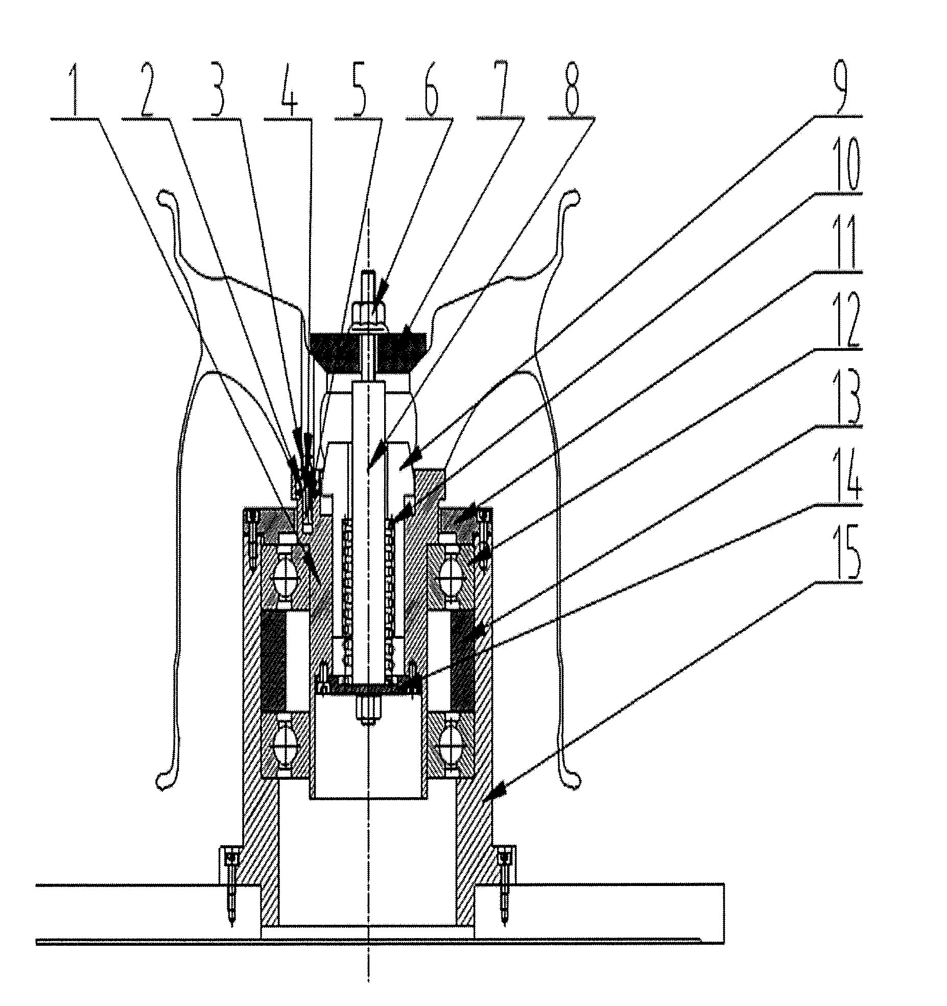
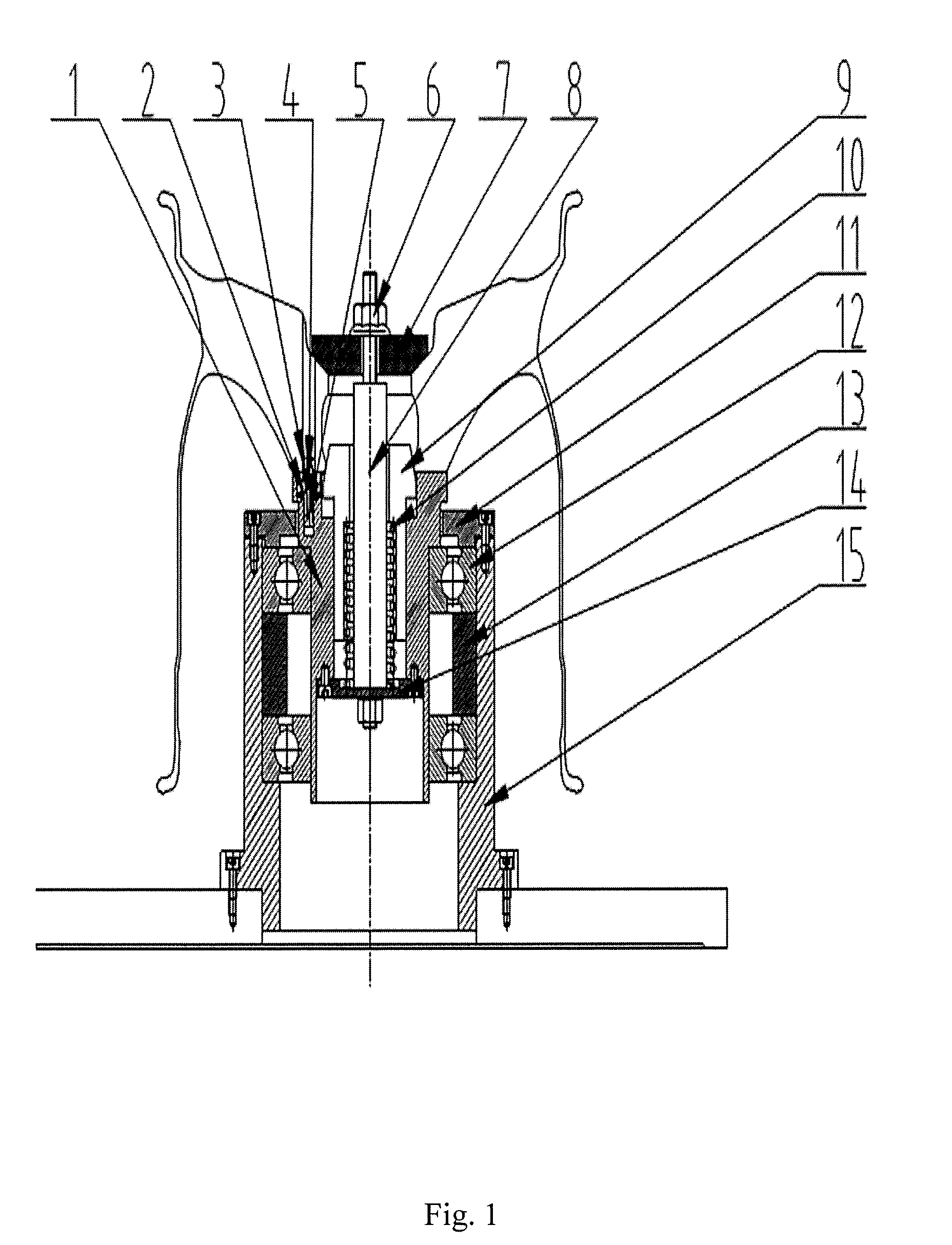
[0008] FIG. 1 is a structural schematic diagram of a secondary clamping device for a wheel in the present application.
[0009] In figures: 1-shaft sleeve, 2-linear bearing, 3-positioning pin, 4-spring A, 5-floating shaft, 6-nut, 7-pressure plate, 8-pull rod, 9-floating column, 10-spring B, 11-bearing end cover, 12-bearing, 13-spacing ring, 14-gland, 15-base.
DETAILED DESCRIPTION OF THE INVENTION
[0010] Details and working conditions of a specific device provided by the present application will be described in detail below in combination with the accompanying drawing.
[0011] A secondary clamping device for a wheel in the present application comprises a shaft sleeve 1, a linear bearing 2, a positioning pin 3, a spring A 4, a floating shaft 5, a nut 6, a pressure plate 7, a pull rod 8, a floating column 9, a spring B 10, a bearing end cover 11, bearings 12, a spacing ring 13, a gland 14 and a base 15. The two bearings 12 and the spacing ring 13 are closed in the base 15 by the bearing end cover 11, wherein the two bearings 12 are connected by the spacing ring 13. The shaft sleeve 1 is mounted on the bearings 12, the linear bearing 2 and the gland 14 are fixed on the shaft sleeve 1, the floating shaft 5 passes through the linear bearing 2 and the spring A 4 in sequence, the positioning pin 3 is fixed at the top of the floating shaft 5, the upper part of the positioning pin 3 is of a positive cone structure, two ends of the spring A 4 are respectively connected with the positioning pin 3 and the linear bearing 2, and the positioning pin 3 can move up and down under the action of the spring A 4. The pull rod 8 is fixed on the gland 14, the pull rod 8 passes through the spring B 10 and the inner hole of the floating column 9, the outer wall of the floating column 9 is connected with the inner hole of the shaft sleeve 1, the upper end face of the floating column 9 is of a positive conical surface structure, two ends of the spring B 10 are respectively connected with the gland 14 and the floating column 9, and the floating column 9 can float up and down under the action of the spring B 10. The pressure plate 7 is mounted on the pull rod 8 by the nut 6.
[0012] Before actual use, the nut 6 and the pressure plate 7 are detached from the pull rod 8. In actual use, when a wheel is put on the device, a central hole and a bolt hole of the wheel are respectively aligned with the floating column 9 and the floating shaft 5, the upper conical surface of the floating column 9 and the upper conical surface of the floating shaft 5 are completely attached to the central hole and the bolt hole of the wheel under the gravity of the wheel and the actions of the spring A 4 and the spring B 10, then the pressure plate 7 is compressed onto the front side of the wheel by the nut 6 so that the wheel moves down, finally, the flange surface of the wheel is in contact with the upper end face of the floating column 9, so far, the clamping operation of the wheel is completed, and machining of the wheel begins.
[0013] The foregoing descriptions of specific exemplary embodiments of the present application have been presented for purposes of illustration and description. They are not intended to be exhaustive or to limit the invention to the precise forms disclosed, and obviously many modifications and variations are possible in light of the above teachings. The exemplary embodiments were chosen and described in order to explain certain principles of the invention and their practical application, to thereby enable others skilled in the art to make and utilize various exemplary embodiments of the present invention, as well as various alternatives and modifications thereof. It is intended that the scope of the invention be defined by the Claims appended hereto and their equivalents.
* * * * *
D00000
D00001
XML
uspto.report is an independent third-party trademark research tool that is not affiliated, endorsed, or sponsored by the United States Patent and Trademark Office (USPTO) or any other governmental organization. The information provided by uspto.report is based on publicly available data at the time of writing and is intended for informational purposes only.
While we strive to provide accurate and up-to-date information, we do not guarantee the accuracy, completeness, reliability, or suitability of the information displayed on this site. The use of this site is at your own risk. Any reliance you place on such information is therefore strictly at your own risk.
All official trademark data, including owner information, should be verified by visiting the official USPTO website at www.uspto.gov. This site is not intended to replace professional legal advice and should not be used as a substitute for consulting with a legal professional who is knowledgeable about trademark law.