Securing Element
HELLMIG; Ralph J. ; et al.
U.S. patent application number 16/069417 was filed with the patent office on 2019-01-31 for securing element. This patent application is currently assigned to EJOT GmbH & Co. KG. The applicant listed for this patent is EJOT GmbH & Co. KG. Invention is credited to Ralph J. HELLMIG, Wilfried PINZL, Ilir SELIMI, Gerd WEIGEL.
| Application Number | 20190032699 16/069417 |
| Document ID | / |
| Family ID | 57914939 |
| Filed Date | 2019-01-31 |


| United States Patent Application | 20190032699 |
| Kind Code | A1 |
| HELLMIG; Ralph J. ; et al. | January 31, 2019 |
SECURING ELEMENT
Abstract
A securing element includes a threaded region, wherein a securing rotational direction and an axial clamping direction are defined by the thread design. The securing element has a head with a head lower face which faces the clamping direction and via which a force-fitting connection with a component can be produced. The head is designed such that the head lower face has an edge region at a radial distance from the head center, and the contour of the head lower face runs opposite the clamping direction in the direction of the head center starting from the edge region, whereby a spring effect can be produced. The edge region has a changing circumferential level in the axial direction. Opposite the securing rotational direction, the circumferential level rises at a rising angle of maximally 15.degree. in the clamping direction over a central angle of at least 65.degree..
| Inventors: | HELLMIG; Ralph J.; (Bad Laasphe, DE) ; PINZL; Wilfried; (Tambach-Dietharz, DE) ; SELIMI; Ilir; (Biedenkopf, DE) ; WEIGEL; Gerd; (Eschenburg, DE) | ||||||||||
| Applicant: |
|
||||||||||
|---|---|---|---|---|---|---|---|---|---|---|---|
| Assignee: | EJOT GmbH & Co. KG Bad Berleburg DE |
||||||||||
| Family ID: | 57914939 | ||||||||||
| Appl. No.: | 16/069417 | ||||||||||
| Filed: | January 12, 2017 | ||||||||||
| PCT Filed: | January 12, 2017 | ||||||||||
| PCT NO: | PCT/EP2017/050556 | ||||||||||
| 371 Date: | July 11, 2018 |
| Current U.S. Class: | 1/1 |
| Current CPC Class: | F16B 39/282 20130101 |
| International Class: | F16B 39/282 20060101 F16B039/282 |
Foreign Application Data
| Date | Code | Application Number |
|---|---|---|
| Jan 12, 2016 | DE | 10 2016 100 446.4 |
Claims
1. A securing element comprising a threaded portion, wherein a rotational fastening direction and an axial clamping direction are defined by the thread design, wherein the securing element has a head with a head underside which faces the clamping direction K and via which a force-fitting connection with a component can be produced, wherein the head is designed such that the head underside has an edge region at a radial distance from the head center, and the contour of the head underside, starting from the edge region towards the center of the head, extends against the clamping direction, whereby a spring effect can be produced, wherein the edge region has a changing circumferential level in the axial direction, and wherein opposite the rotational fastening direction, the circumferential level increases at a pitch angle (.alpha.) of maximally 15.degree. in the clamping direction over a central angle of at least 65.degree..
2. The securing element according to claim 1, wherein the rise is monotonic.
3. The securing element according to claim 1, wherein the rise extends over a central angle (.beta.) of at least 70.degree..
4. The securing element according to claim 1, wherein the rise extends at a pitch angle (a) of 10.degree. at the most.
5. The securing element according to claim 1, wherein the descent following the rise is at an angle (.delta.) of descent of more than 45.degree., but <=90.degree. with respect to a plane normal to the screw axis.
6. The securing element according to claim 1, wherein the descent extends over a central angle range (.beta.) of 15.degree. at the most.
7. The securing element according to claim 1, wherein the rise width An and the descent width Ab satisfy the relationship Ab*tan(.delta.)=An*sin(.alpha.).
8. The securing element according to claim 1, wherein the securing element is a screw which has a shank that is threaded and arranged in the center of the head and extends in the clamping direction.
9. The securing element according to claim 1, wherein the securing element is a nut in which the thread is arranged in a center of a head thereof.
10. The securing element according to claim 1, wherein the rise is strictly monotonic.
11. The securing element according to claim 1, wherein the rise extends at a pitch angle (a) of 5.degree. at the most.
12. The securing element according to claim 1, wherein the descent following the rise is at an angle (.delta.) of descent of more than 65.degree., but <=900 with respect to a plane normal to the screw axis.
13. The securing element according to claim 2, wherein the rise extends over a central angle (.beta.) of at least 70.degree..
14. The securing element according to claim 2, wherein the rise extends at a pitch angle (a) of 10.degree. at the most.
15. The securing element according to claim 3, wherein the rise extends at a pitch angle (a) of 10.degree. at the most.
16. The securing element according to claim 2, wherein the descent following the rise is at an angle (.delta.) of descent of more than 45.degree., but <=900 with respect to a plane normal to the screw axis.
17. The securing element according to claim 3, wherein the descent following the rise is at an angle (.delta.) of descent of more than 45.degree., but <=900 with respect to a plane normal to the screw axis.
18. The securing element according to claim 4, wherein the descent following the rise is at an angle (.delta.) of descent of more than 45.degree., but <=900 with respect to a plane normal to the screw axis.
19. The securing element according to claim 2, wherein the descent extends over a central angle range (.beta.) of 15.degree. at the most.
20. The securing element according to claim 3, wherein the descent extends over a central angle range (.beta.) of 15.degree. at the most.
Description
[0001] The invention relates to a securing element according to the preamble of claim 1.
[0002] In a known manner, the screw comprises a threaded shank and a head, with the design of the thread defining a screwing-in direction and the head, at its end facing the shank, furthermore having a diameter which is larger than the diameter of the shank, and with the head being designed such that, in an axial direction towards the shank, the edge region of the head is spaced from its connection region on the shank, thus allowing a preload to be generated. This type of a screw is also referred to as a spring-head screw.
[0003] A generic screw is disclosed in WO 2012/076360 A1 that has an undulating flange in its edge region.
[0004] Due to the conical shape of the head, a preload can be generated on a component, which preload is generated by urging the undulation into a flattened configuration against the component.
[0005] With this type of spring-head screw, there is a likelihood of the screw becoming loose, in particular in case of high dynamic loads.
[0006] A generic spring-head screw according to EP 0 028 746 A1 can be used as a screw that is capable of indicating the applied contact force. This disclosure relates to a screw which has a flat annular bottom surface and which has spring sections in sectors. The spring section has a circumferential undulating edge section. This edge section is coaxially offset from the shank and radially offset from the connection area. The undulating edge section is flattened as the screw is tightened, thus indicating that the maximum tightening torque has been applied. Should the screw become loose in the course of time, this will be indicated by the reappearance of the undulation in its edge section
[0007] This allows any loosening of the screw to be detected at an early stage.
[0008] It is an object of the invention to increase the release torque of a spring-head screw and to improve its dynamic properties.
[0009] This object is achieved by the characterizing features of claim 1 in conjunction with the features specified in its preamble.
[0010] The dependent claims provide advantageous embodiments of the invention.
[0011] In a known manner, the securing element comprises a threaded portion, with the design of said thread defining a rotational fastening direction and an axial clamping direction. Furthermore, the securing element has a head whose underside faces the clamping direction, which underside can be used to produce a force-fitting connection with a component. The head is designed such that an edge region of the head underside is radially spaced from the center of the head, and the contour of the head underside, starting from the edge region towards the center of the head, furthermore extends in a direction opposite to the clamping direction, whereby a spring effect can be produced. Moreover, in the axial direction, the edge region also has a varying circumferential level.
[0012] According to the invention, in a direction opposite to the rotational fastening direction, the circumferential level increases over a central angle (.beta.) of at least 65.degree. with a maximum pitch angle (a) of 15.degree. in the clamping direction. After reaching an apex, the circumferential level decreases again against the clamping direction.
[0013] As the head increasingly presses down on the component to be clamped, also the central region of the head underside is urged into contact with the component to be clamped. The spring head is tightened to produce a preload in the elastic region of the head.
[0014] The slight rise in the height level thus guarantees a low-friction fastening operation, which will also prevent damage to the surface of a component to be clamped. This is especially advantageous in the case of coated materials. Moreover, most of the torque used for the screw connection can also be used for applying a preload on the component to be clamped so that there is no need to convert it into frictional energy.
[0015] Preferably, the rise is monotonic, in particular strictly monotonic. This will ensure that the spring head is pressed continuously against a component.
[0016] According to yet another advantageous embodiment, the level rises over a sector central angle of at least 70.degree.. Preferably, the level rises at a pitch angle of 10.degree. at the most, in particular of 5.degree. at the most.
[0017] This allows the contact pressure to be increased in a gentle manner so as to prevent damage to the surface of a component.
[0018] Consistently, after each rise, the level immediately drops again following a rise. This preferably occurs at an angle of descent (.delta.) of more than 45.degree., in particular of more than 65.degree., but in particular at an angle of less than or equal to 90.degree. relative to a plane normal to the screw axis. As a result, a sharp edge is produced which serves to secure the screw against unscrewing without requiring an undercut. This makes the securing element easy to manufacture.
[0019] It can further be provided that the height level descends over a sector central angle of 15.degree. at the most.
[0020] Owing to the very flat rise and the steep descent of levels, a preload can be applied gently without dam-aging the surface of a component, and this will also secure the securing element against unscrewing.
[0021] A rising section with a subsequent descent creates a cam. According to the invention, any number of cams between one and five can be formed on the underside of the screw head. For a rising section, its sector central angle is preferably in a range of between 345.degree. and approximately 360.degree.. If there are three rising sections, the sector central angle can range between 105.degree. and approximately 120.degree..
[0022] For the formation of a cam, the rise width An and the descent width Ab at the same radial distance from the central axis, as seen in a flat-pattern view the surface is unwind, satisfy the relationship Ab(.gamma.)*tan (.delta.)=An(.beta.)*sin(.alpha.).
[0023] The securing element may preferably be formed as a screw. As is well known, in this embodiment, the threaded shank of the screw connects to the underside of the screw head coaxially to the latter. In particular, the head has drive contours which are preferably arranged on the head top opposite the head underside.
[0024] In another embodiment, the securing element may also be formed as a nut, and in this embodiment, an internal thread is arranged concentrically in the screw head and the drive is in particular formed laterally.
[0025] Further advantages, features and possible applications of the present invention will become apparent from the following description in which reference is made to the embodiments illustrated in the drawings.
[0026] In the drawings:
[0027] FIG. 1 is a partial sectional view of a securing element (screw) having a retaining structure;
[0028] FIG. 2 is a perspective view of a securing element head, according to the invention, of a securing element having a retaining structure;
[0029] FIG. 3 is a perspective view of a securing element head, according to the invention, of a securing element having three retaining structures;
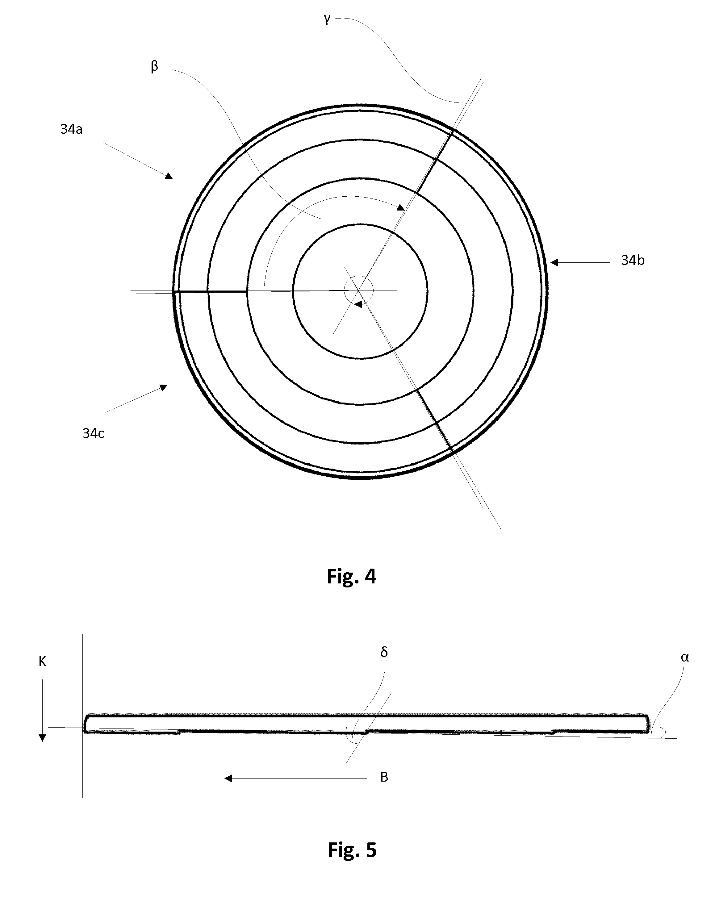
[0030] FIG. 4 is a plan view of the head underside of the screw head of FIG. 3;
[0031] FIG. 5 is a flat-pattern view of the edge region of the head of FIG. 3;
[0032] FIG. 6a is a perspective view of a securing element head, according to the invention, of a securing element having three retaining structures with an offset, and
[0033] FIG. 6b is a lateral view of the head of FIG. 6a.
[0034] FIG. 1 is a partial sectional view of a securing element according to the invention in the form of a screw 10 having a head 12. The head 12 transitions into a threaded shank 14. The thread defines a rotational fastening direction B and a clamping direction K. Radially spaced from the center of the head, the head 12 has an edge region 16 which is brought into contact with a component to be clamped. As illustrated, on the head underside, the contour of the head, starting from the edge region 16, extends against the clamping direction K. This design yields a spring effect of the edge region 16 relative to the center of the head. The edge region 16 changes in height level in the axial direction (which will be described in more detail in the following figures), with a rise in the clamping direction K extending over a sector central angle .beta. of 358.degree.. The rise extends at an angle of less than 2.degree., which ensures that the head 12 will be pressed onto the component to be clamped (not shown) in a very gentle manner. Following the rising region, the height level drops again to the original starting level over a sector central angle .gamma. of 2.degree. in a transition region 20, against the clamping direction K. This steep drop secures the screw against unscrewing against the rotational fastening direction B. The slight rise in height level in the edge region prevents unscrewing and is easy on the surface of a component to be clamped.
[0035] FIG. 2 is a perspective view of the head 12 showing the head underside of a securing element according to the invention, similar to the view of FIG. 1. This view clearly shows the edge region 16 and the transition region 20 and the hat-like contour of the head.
[0036] FIG. 3 is a perspective view of a head 32 of a securing element 30 according to the invention with a right-hand thread. For reasons of clarity, the shank is not shown in this view. A corresponding securing element 30 is designed in the form of a securing element 30 having a head 32. The embodiment shown in FIG. 3 has three rising sections 34a, 34b, 34c over a sector central angle .beta. of 118.degree., with the descent extending over a sector central angle of 2.degree.. These three sections enable the head 32 to exert a more uniform contact pressure on the component to be clamped (not shown). In addition, the larger number of retaining structures 36a, 36b, 36c resulting from the steep drop as compared to the embodiment of FIG. 1 results in an increased release torque of the screw, with stress being more uniformly distributed in the head 32.
[0037] FIG. 4 is a plan view of the head underside of the head 32 of FIG. 3. The three rising sections 34a, 34b, 34c each extend over a sector central angle .beta. of 118.degree., with the retaining structures being provided by a height level drop to the starting level of approx. .gamma.=2.degree..
[0038] FIG. 5 is a flat-pattern view of the edge region of the head 32 of FIG. 3 which more clearly illustrates the course of the height level of the edge region. This drawing shows the height level in the direction K against the rotational fastening direction B over the sector central angle .beta.. As can be gathered from this illustration, the height level rises in the clamping direction over 118.degree. with an upward slope of about 1 and then drops over a range of 2.degree. back to the starting level from where it rises again in the further course. This creates the retaining structures already described with reference to FIG. 3 which guarantee an effective increase of the release torque with clamping properties that will not damage the surface.
[0039] FIG. 6a is a lateral view of a head 48 of another embodiment of a securing element 40 according to the invention with a right-hand thread. For reasons of clarity, the screw shank has been omitted from this view. In this embodiment, the level change of the edge section 42 on the head underside 44 is analogously present on the head top 46. The offset 50 results in a uniform thickness of the head in its edge region 42, which ensures uniform stress distribution in the head as the securing element 40 is being tensioned, at the same time retaining the volume displaced during forming in the manufacturing process.
[0040] FIG. 6b is a lateral view of the head 48 of FIG. 6a which clearly shows the course of the offset 50.
* * * * *
D00000
D00001
D00002
D00003
D00004
XML
uspto.report is an independent third-party trademark research tool that is not affiliated, endorsed, or sponsored by the United States Patent and Trademark Office (USPTO) or any other governmental organization. The information provided by uspto.report is based on publicly available data at the time of writing and is intended for informational purposes only.
While we strive to provide accurate and up-to-date information, we do not guarantee the accuracy, completeness, reliability, or suitability of the information displayed on this site. The use of this site is at your own risk. Any reliance you place on such information is therefore strictly at your own risk.
All official trademark data, including owner information, should be verified by visiting the official USPTO website at www.uspto.gov. This site is not intended to replace professional legal advice and should not be used as a substitute for consulting with a legal professional who is knowledgeable about trademark law.