An Apparatus And Method For Compressing Fluid
ADLER; Robert ; et al.
U.S. patent application number 16/073186 was filed with the patent office on 2019-01-31 for an apparatus and method for compressing fluid. This patent application is currently assigned to CRYOSTAR SAS. The applicant listed for this patent is CRYOSTAR SAS. Invention is credited to Robert ADLER, Ekkehardt KLEIN, Christoph NAGL, Lukas TOBEINER.
| Application Number | 20190032646 16/073186 |
| Document ID | / |
| Family ID | 55590359 |
| Filed Date | 2019-01-31 |


| United States Patent Application | 20190032646 |
| Kind Code | A1 |
| ADLER; Robert ; et al. | January 31, 2019 |
AN APPARATUS AND METHOD FOR COMPRESSING FLUID
Abstract
The invention provides an apparatus for compressing a first fluid. The apparatus comprises a compressor piston comprising a piston cylinder and a piston assembly slidably mounted therein. The piston assembly comprises first and second spaced apart piston members defining a space therebetween. The space is configured to contain a second fluid used to cause compression of the first fluid. The piston assembly further comprises means for feeding second fluid to the space between the first and second piston members.
| Inventors: | ADLER; Robert; (Gerasdorf, AT) ; KLEIN; Ekkehardt; (Katzelsdorf, AT) ; NAGL; Christoph; (Alland, AT) ; TOBEINER; Lukas; (Breitenfurt bei Wien, AT) | ||||||||||
| Applicant: |
|
||||||||||
|---|---|---|---|---|---|---|---|---|---|---|---|
| Assignee: | CRYOSTAR SAS Hessingue FR |
||||||||||
| Family ID: | 55590359 | ||||||||||
| Appl. No.: | 16/073186 | ||||||||||
| Filed: | January 17, 2017 | ||||||||||
| PCT Filed: | January 17, 2017 | ||||||||||
| PCT NO: | PCT/EP2017/025009 | ||||||||||
| 371 Date: | July 26, 2018 |
| Current U.S. Class: | 1/1 |
| Current CPC Class: | F04B 35/008 20130101; F04B 25/005 20130101; F04B 37/18 20130101; F04B 9/1073 20130101; F04B 53/141 20130101; F04B 39/0016 20130101; F04B 53/142 20130101; F04B 9/1176 20130101; F04B 39/0011 20130101; F04B 9/1076 20130101; F04B 9/107 20130101 |
| International Class: | F04B 25/00 20060101 F04B025/00; F04B 9/107 20060101 F04B009/107 |
Foreign Application Data
| Date | Code | Application Number |
|---|---|---|
| Jan 28, 2016 | GB | 1601602.4 |
Claims
1. An apparatus for compressing a first fluid, the apparatus comprising a compressor piston comprising a piston cylinder and a piston assembly slidably mounted therein, wherein the piston assembly comprises first and second spaced apart piston members defining a space therebetween, which space is configured to contain a second fluid used to cause compression of the first fluid, and means for feeding second fluid to the space between the first and second piston members.
2. An apparatus according to claim 1, wherein the apparatus comprises a storage tank configured to store the second fluid therein, and the means for feeding the second fluid to the space between the first and second piston members comprises a pump and at least one second fluid feed conduit extending between the storage tank and the space between the piston members along which the fluid is fed, preferably wherein the pump is activated during the non-compression stage and the second fluid disposed in the space between the first and second piston members is fluidly connected to the storage tank via at least one second fluid leakage conduit.
3. An apparatus according to claim 2, wherein the second piston member comprises a valve configured to control the flow of the second fluid through the at least one second fluid feed conduit into the space between the piston members, preferably wherein the valve comprises biasing means configured to bias the valve into a closed configuration in the second fluid feed conduit, more preferably wherein the biasing means comprises a spring, optionally a helical spring or a cup spring.
4. An apparatus according to claim 3, wherein the second piston member comprises actuation means configured to activate the valve in response to a change in pressure on the first seal or in response to the position of the first piston member with respect to an actuation set-point, preferably wherein the pump is configured to pump the second fluid from the storage tank, through the open valve activated by the actuation means, and along one or more conduit into the space between the first and second piston members.
5. An apparatus according to claim 4, wherein the actuation means is configured to open the valve when the pressure on the first seal increases, and activate the pump to pump second fluid through the valve and/or the actuation means is configured to close the valve when the pressure on the first seal decreases, and deactivate the pump to prevent pumping of second fluid, and/or wherein when the pressure on the first fluid side of the first seal increases due to leakage of the second fluid through the second seal, the first piston member is configured to be urged towards the second piston member, thereby resulting in the actuation means opening the valve, and/or wherein the pre-stress tension of the biasing means exerted on the actuating means substantially corresponds to the weight of the first piston member and the friction created between the cylinder tube and the first seal.
6. An apparatus according to claim 4, wherein the actuation means is configured to open the valve when the position of the first piston member reaches the actuation set-point and/or the actuation means is configured to close the valve when the position of the first piston member moves beyond the actuation set-point.
7. An apparatus according to claim 1, wherein the first piston member is configured to oscillate within the cylinder tube, and is sealed with the cylinder tube by a first radial seal, optionally a stem seal or a piston seal, and the second piston member is configured to oscillate within the cylinder tube, and is sealed with the cylinder tube by a second radial seal, optionally a stem seal or a piston seal, and the first piston member is substantially centrally mounted on the second piston member, and is guided concentrically thereby.
8. An apparatus according to claim 1, wherein the first fluid that is to be compressed contacts one side of the first piston member, and the second fluid contacts the opposite side of the first piston member, preferably wherein the apparatus comprises a leakage cycle return line to the space between the first and second piston members, because, during use of the compressor piston, any leakage of the second fluid at the second seal is automatically balanced out by a replenishment flow of second fluid.
9. An apparatus according to claim 1, wherein the second piston member comprises one or more conduits which extend radially outwardly from the valve to the space between the piston members, preferably wherein the one or more conduits extend diagonally from the valve to the space between the piston members.
10. An apparatus according to claim 1, wherein the pressure difference between the side of the first piston member contacting the first fluid, and the side contacting the second fluid is less than 75 Bar, 50 Bar, 25 Bar, 15 Bar, 10 Bar, 5 Bar, or less than 3 Bar and the compressor piston is configured to increase the pressure of the first fluid to between 100 bara and 1500 bara.
11. An apparatus according to claim 1, wherein the first fluid comprises gas, such as natural gas, fuel gas, hydrogen, gaseous hydrocarbon, liquefied combustion gas, nitrogen, helium, oxygen, and a noble gas, such as argon, or a mixture thereof and the second fluid comprises liquid, which is substantially incompressible, preferably wherein the second fluid comprises an ionic liquid, an LOHC (liquid organic hydrogen carrier), semiheavy water (HDO), deuterium oxide (heavy water), water, or hydraulic oil, or a mixture thereof.
12. An apparatus according to claim 1, wherein the apparatus is configured to use an ionic liquid cushion disposed between the piston assembly and the first fluid to be compressed, preferably wherein the ionic liquid cushion comprises or consists of a substantially pure ionic liquid, or a mixture of an ionic liquid and LOHC.
13. An apparatus according to claim 1, wherein the apparatus comprises: an oscillating compressor and/or a hydraulically driven compressor; and/or a liquid piston compressor and/or an ionic compressor; and/or a single-stage compressor or a multi-stage compressor; and/or a plunger functionally connected to one or more displacement pistons configured to oscillate within a housing, and configured to displace the second fluid to and from the compressor piston, thereby compressing the first fluid therein, preferably wherein oscillation of the or each displacement piston driven by the plunger is facilitated by a lubricant which is fed into the housing via at least one inlet, wherein the lubricant is hydraulic oil, LOHC or an ionic liquid, or mixtures thereof.
14. A method of compressing a first fluid, the method comprising: feeding a first fluid into a compressor piston comprising a piston cylinder and a piston assembly slidably mounted therein, wherein the piston assembly comprises first and second spaced apart piston members defining a space therebetween, which space is configured to contain a second fluid used to cause compression of the first fluid; and feeding a second fluid to the space between the first and second piston members, and compressing the first fluid.
15. A method according to claim 14, wherein the method uses an apparatus comprising a compressor piston comprising a piston cylinder and a piston assembly slidably mounted therein, wherein the piston assembly comprises first and second spaced apart piston members defining a space therebetween, which space is configured to contain a second fluid used to cause compression of the first fluid, and means for feeding second fluid to the space between the first and second piston members.
Description
[0001] The present invention relates to an apparatus for compressing fluid. In particular, the invention relates to compressors, and particularly, although not exclusively, to oscillating compressors, and especially to hydraulically driven compressors. The invention relates to piston compressors or ionic compressors, and either single-stage or multi-stage compressors. The invention primarily relates to seals within such compressors, in particular axial seals, which can be executed both as stem seals or piston seals. The invention further extends to methods of compressing fluids, and especially gas.
[0002] The gas seal in a compressor that is fitted with leakage relief is subjected to the full gas pressure during the compression process (equivalent to the actual gas-pressure), which will inevitably lead to wear during continued use. Furthermore, with rising back-pressure on the seal within the compressor, wear on the seal also increases as a result of elevated pre-stresses. Experience has shown that the service life of a gas seal subjected to such stresses, given adequate dimensions, is in the range of 2500-3000 km.
[0003] There is therefore a need to provide improved compressor designs, which increase the service life of the seals. The present invention arises from the inventor's work in trying to overcome the problems associated with the prior art.
[0004] In accordance with a first aspect of the invention, there is provided an apparatus for compressing a first fluid, the apparatus comprising a compressor piston comprising a piston cylinder and a piston assembly slidably mounted therein, wherein the piston assembly comprises first and second spaced apart piston members defining a space therebetween, which space is configured to contain a second fluid used to cause compression of the first fluid, and means for feeding second fluid to the space between the first and second piston members.
[0005] In prior art compressors, the fluid seal in contact with the compressed fluid is exposed to a pressure equivalent to the actual gas-pressure, which causes significant wear on the seal. However, in contrast, in the apparatus of the invention, the piston assembly comprises two spaced apart piston members, resulting in the fluid seal in the compressor being exposed to a reduced pressure of only 2 bar. Thus, the apparatus results in a significant reduction of load on the fluid seal, leading to reduced wear and tear. Hence, advantageously, the apparatus results in extended wear time for the piston seals, due to excellent lubrication created between the piston assembly and the cylinder tube. This provides enhanced corrosion protection, and mechanical protection against compressor knocking, and results in low noise emission. Further advantages include longer service lives leading to lower maintenance costs, which results in increased plant availability.
[0006] Preferably, the apparatus comprises a storage tank configured to store the second fluid therein. Preferably, the means for feeding the second fluid to the space between the first and second piston members comprises a pump, and preferably at least one second fluid feed conduit extending between the storage tank and the space between the piston members along which the fluid is fed.
[0007] Preferably, the first piston member (referred to herein as a "floating piston") is configured to oscillate within the cylinder tube, and is preferably sealed with the cylinder tube by a first radial seal. The first radial seal may be a stem seal or a piston seal. Preferably, the first piston member is substantially centrally mounted on the second piston member, and is guided concentrically thereby. Preferably, the second piston member (referred to herein as a "main piston") is configured to oscillate within the cylinder tube, and is preferably sealed with the cylinder tube by a second radial seal. The second radial seal may be a stem seal or a piston seal.
[0008] Preferably, the first fluid that is to be compressed contacts one side of the first piston member, and the second fluid contacts the opposite side of the first piston member. Preferably, the second fluid acts as a lubricating fluid when disposed in between the first and second piston members of the piston assembly, as it acts to reduce friction between the first radial seal and the cylinder tube. Preferably, the second fluid acts as a driving fluid when disposed underneath the piston assembly, as it serves to cause the piston assembly to oscillate within the cylinder tube, thereby compressing the first fluid.
[0009] Preferably, the second fluid disposed in the space between the first and second piston members is fluidly connected, preferably via at least one second fluid leakage conduit, to the storage tank. Hence, any of the second fluid which leaks through the second seal is fed to the storage tank. Advantageously, therefore, the apparatus comprises a leakage cycle return line to the space between the first and second piston members, because, during use of the compressor piston, any leakage of the second fluid at the second seal is automatically balanced out by a replenishment flow of second fluid.
[0010] Preferably, the second piston member comprises a valve configured to control the flow of the second fluid through the at least one second fluid feed conduit into the space between the piston members. Preferably, the valve comprises biasing means configured to bias the valve into a closed configuration in the second fluid feed conduit. The biasing means preferably comprises a spring, and more preferably a helical spring or a cup spring.
[0011] Preferably, the second piston member comprises actuation means configured to activate the valve in response to a change in pressure on the first seal, or in response to the position of the first piston member with respect to an actuation set-point. Preferably, the actuation means is configured to activate the pump in response to a change in pressure on the first seal, or in response to the position of the first piston member with respect to an actuation set-point. Preferably, the actuation means is configured to open the valve when the pressure on the first seal increases, and preferably activates the pump to pump second fluid through the valve. Conversely, preferably the actuation means is configured to close the valve when the pressure on the first seal decreases, and preferably deactivate the pump to prevent pumping of second fluid.
[0012] By way of example, therefore, when the pressure on the first fluid side of the first seal increases due to leakage of the second fluid through the second seal, the first piston member is preferably configured to be urged towards the second piston member, thereby resulting in the actuation means opening the valve.
[0013] In another preferred embodiment, the actuation means is configured to open the valve when the position of the first piston member reaches the actuation set-point and/or the actuation means is configured to close the valve when the position of the first piston member moves beyond the actuation set-point. It will be appreciated that the valve and pump may be activated by the actuation means, when the position of the floating piston falls below the actuating set-point, which can occur due to fluid losses, or entrapped compressible gases. This may not necessarily result in a decrease or increase of pressure on the first seal.
[0014] Preferably, the pump is configured to pump the second fluid from the storage tank, through the open valve activated by the actuation means, and along one or more conduit into the space between the first and second piston members. Preferably, the second piston member comprises one or more conduits which extend radially outwardly from the valve to the space between the piston members. Preferably, the one or more conduits extend diagonally from the valve to the space between the piston members.
[0015] Advantageously, a substantially constant depth of the second fluid is maintained between the first and second piston members. The second fluid may be pumped into the space between the piston members at any stage in the compression process. However, preferably the pump is activated during the non-compression stage, i.e. when the piston assembly is disposed at, or adjacent to, the bottom of the cylinder tube.
[0016] Preferably, the apparatus is configured such that the pressure between the first fluid side of the first piston member and the second fluid is substantially balanced out. Preferably, the pre-stress tension of the biasing means exerted on the actuating means substantially corresponds to the weight of the first piston member and the friction created between the cylinder tube and the first seal.
[0017] Preferably, the pressure difference between the side of the first piston member contacting the first fluid, and the side contacting the second fluid is less than 75 Bar, more preferably less than 50 Bar, even more preferably less than 25 Bar, and still more preferably less than 15 Bar. More preferably, the pressure difference between the side of the first piston member contacting the first fluid, and the side contacting the second fluid is less than 10 Bar, preferably less than 5 Bar, and most preferably less than 3 Bar.
[0018] As a result, small radial forces between the first piston member and the first radial seal results in less wear and tear. Advantageously, the apparatus is configured to subject the first seal only to the pre-tension pressure that is defined by the seal, in order to minimise wear thereon.
[0019] Preferably, the compressor piston comprises an inlet through which uncompressed first fluid is fed therein, and an outlet through which compressed first fluid exits. Preferably, the pressure of the inlet fluid is about 1-200 barg; more preferably about 1-30 barg; and most preferably about 3-10 barg.
[0020] Preferably, the compressor piston is configured to increase the pressure of the first fluid to between 100 bara and 1500 bara. More preferably, the compressor piston is configured to increase the pressure of the first fluid to between 150 bara and 1250 bara. Most preferably, the compressor piston is configured to increase the pressure of the first fluid to between 300 bara and 1000 bara. Preferably, the pressure of the outlet fluid is about 350 Bar.
[0021] It may be appreciated that the desired pressure of the first fluid varies depending upon the first fluid that is used. Accordingly, when the first fluid is hydrogen, the compressor piston may be configured to increase the pressure of the first fluid to between 500 bara and 1500 bara, more preferably to between 700 bara and 1400 bara, and most preferably to between 800 bara and 1300 bara.
[0022] Alternatively, when the first fluid is natural gas, the compressor piston may be configured to increase the pressure of the gas to between 100 bara and 700 bara, more preferably to between 200 bara and 600 bara, and most preferably to between 300 bara and 500 bara.
[0023] The first fluid may comprise liquid. Preferably, however, the first fluid comprises gas, such as natural gas, fuel gas, hydrogen, gaseous hydrocarbon, liquefied combustion gas, nitrogen, helium, oxygen, and a noble gas, such as argon, or a mixture thereof. More preferably, the first fluid comprises a fuel gas, for example natural gas or hydrogen.
[0024] The second fluid may comprise liquid, which is preferably substantially incompressible. Preferably, the second fluid comprises an ionic liquid, an LOHC (liquid organic hydrogen carrier), semi-heavy water (HDO), deuterium oxide (heavy water), water, or hydraulic oil, or a mixture thereof. Most preferably, the second fluid comprises an LOHC or an ionic liquid. An ionic liquid consists substantially exclusively of ions, and is a class of material that is liquid at temperatures below 100.degree. C. LOHCs are carbon-based liquids with very similar properties to ionic liquids. Advantages of ionic liquids and LOHCs are that they exhibit low or no vapor pressure, good lubricating properties, essentially no gas solubility, high thermal stability, and high heat capacity.
[0025] In one embodiment, and preferably embodiments in which the second fluid is an ionic liquid, the apparatus is configured to use an ionic liquid cushion disposed between the piston assembly and the first fluid to be compressed. Preferably, the ionic liquid cushion is disposed on top of the first (i.e. floating piston member) and fills out all of the dead space whilst in the compression phase. The ionic liquid cushion preferably comprises a fluid with a low vapour pressure, and may comprise or consist of a substantially pure ionic liquid, or a mixture of an ionic liquid and LOHC.
[0026] Preferably, the apparatus comprises an oscillating compressor. Preferably, the apparatus comprises a hydraulically driven compressor. In one preferred embodiment, the apparatus comprises a piston compressor. Preferably, the apparatus comprises a liquid piston compressor, in which the second fluid (preferably a liquid) is used to drive compression of the first fluid (preferably a gas). In another preferred embodiment, the apparatus comprises an ionic compressor.
[0027] In one embodiment, the apparatus comprises a single-stage compressor. Preferably, the apparatus comprises a plunger functionally connected to one or more displacement pistons configured to oscillate within a housing, and configured to displace the second fluid to and from the compressor piston, thereby compressing the first fluid therein. The displacement pistons may be connected in series. Oscillation of the or each displacement piston driven by the plunger is facilitated by a lubricant which is fed into the housing via at least one inlet. In some embodiments, the lubricant for the plunger may be hydraulic oil, LOHC or an ionic liquid, or mixtures thereof.
[0028] In another embodiment, the apparatus preferably comprises a multi-stage compressor (e.g. 2-stage, 3-stage or 4-stage) comprising a plurality of compressor stages connected in a series. Preferably, the apparatus comprises between one and twenty compressor stages. More preferably, the apparatus comprises between two and ten compressor stages. Most preferably, the apparatus comprises between three and five compressor stages. In a most preferred embodiment, the apparatus comprises four compressor stages connected in series.
[0029] The apparatus may comprise a multistage compressor comprising a plurality of compressor stages connected in parallel. Advantageously, this would increase the throughput of the compressor.
[0030] Accordingly, in one embodiment, the apparatus may comprise a plurality of series, wherein each series comprises a plurality of compressor stages connected in a series and the plurality of series are connected parallel.
[0031] According to a second aspect of the invention, there is provided a method of compressing a first fluid, the method comprising: [0032] feeding a first fluid into a compressor piston comprising a piston cylinder and a piston assembly slidably mounted therein, wherein the piston assembly comprises first and second spaced apart piston members defining a space therebetween, which space is configured to contain a second fluid used to cause compression of the first fluid; and [0033] feeding a second fluid to the space between the first and second piston members, and compressing the first fluid.
[0034] Preferably, the method of the second aspect comprises use of the apparatus of the first aspect.
[0035] Preferably, the method comprises pumping the second fluid to the space between the first and second piston members, preferably along at least one second fluid feed conduit extending between a second fluid storage tank and the space between the piston members.
[0036] Preferably, the method comprises feeding any of the second fluid, which leaks through a second radial seal disposed between the second piston member and the cylinder tube, to the storage tank.
[0037] Preferably, the method comprises controlling the flow of the second fluid through the at least one second fluid feed conduit into the space between the piston members via a valve disposed in the at least one second fluid feed conduit. Preferably, the method comprises biasing the valve into a closed configuration in the second fluid feed conduit. The biasing means preferably comprises a spring, and more preferably a helical spring.
[0038] Preferably, the method comprises activating the valve in response to a change in pressure on the first radial seal, or in response to the position of the first piston member with respect to an actuation set-point. Preferably, the method comprises activating the pump in response to a change in pressure on the first radial seal, or in response to the position of the first piston member with respect to an actuation set-point. Preferably, the method comprises opening the valve when the pressure on the first radial seal increases, and preferably pumping the second fluid through the valve. Preferably, the method comprises closing the valve when the pressure on the first radial seal decreases, and preferably deactivating the pump to prevent pumping of second fluid.
[0039] In use, when the pressure on the first fluid side of the first radial seal increases due to leakage of the second fluid through the second radial seal, the method comprises urging the first piston member towards the second piston member, thereby resulting in the opening of the valve.
[0040] The method may comprise opening the valve when the position of the first piston member reaches the actuation set-point and/or closing the valve when the position of the first piston member moves beyond the actuation set-point.
[0041] Preferably, the method comprises pumping the second fluid from the storage tank, through the open valve, and along one or more conduit into the space between the first and second piston members. Preferably, the method comprises pumping second fluid along one or more conduits which extend radially outwardly from the valve to the space between the piston members.
[0042] Preferably, the method comprises maintaining a substantially constant depth of the second fluid between the first and second piston members. The method may comprise pumping the second fluid into the space between the piston members at any stage in the compression process. However, preferably the method comprises activating the pump during the non-compression stage, i.e. when the piston assembly is disposed at, or adjacent to, the bottom of the cylinder tube.
[0043] Preferably, the method comprises balancing the pressure between the first fluid side of the first piston member and the second fluid. Preferably, the pressure difference between the side of the first piston member contacting the first fluid, and the side contacting the second fluid is less than 75 Bar, more preferably less than 50 Bar, even more preferably less than 25 Bar, and still more preferably less than 15 Bar. More preferably, the pressure difference between the side of the first piston member contacting the first fluid, and the side contacting the second fluid is less than 10 Bar, preferably less than 5 Bar, and most preferably less than 3 Bar.
[0044] Preferably, the method comprises feeding uncompressed first fluid into the compressor piston via an inlet, and feeding compressed fluid through an outlet. Preferably, the method comprises use of a liquid piston compressor, in which the second fluid (preferably a liquid) is used to drive compression of the first fluid (preferably a gas). In another preferred embodiment, the apparatus comprises an ionic compressor.
[0045] Preferably, the method comprises displacing the second fluid to and from the compressor piston, thereby compressing the first fluid therein, by means of one or more displacement pistons configured to oscillate within a housing.
[0046] The first fluid may comprise liquid. Preferably, the first fluid comprises gas, such as natural gas, fuel gas, hydrogen, gaseous hydrocarbon, liquefied combustion gas, nitrogen, helium, oxygen, and a noble gas, such as argon, or a mixture thereof.
[0047] The second fluid may comprise liquid, which is preferably substantially incompressible. Preferably, the second fluid comprises an ionic liquid, an LOHC (liquid organic hydrogen carrier), semiheavy water (HDO), deuterium oxide (heavy water), water, or hydraulic oil, or a mixture thereof. Most preferably, the second fluid comprises an LOHC or an ionic liquid.
[0048] In one embodiment, and preferably embodiments in which the second fluid is an ionic liquid, the method comprises use of an ionic liquid cushion disposed between the piston assembly and the first fluid to be compressed. Preferably, the ionic liquid cushion is disposed on top of the first piston member, and fills out all of the dead space whilst in the compression phase. The ionic liquid cushion preferably comprises a fluid with a low vapour pressure, and may comprise or consist of a substantially pure ionic liquid, or a mixture of an ionic liquid and LOHC.
[0049] All features described herein (including any accompanying claims, abstract and drawings), and/or all of the steps of any method or process so disclosed, may be combined with any of the above aspects in any combination, except combinations where at least some of such features and/or steps are mutually exclusive.
[0050] Embodiments of the present invention will now be described, by way of example only, with reference to the accompanying drawings, in which:
[0051] FIG. 1 is a schematic diagram of a first embodiment of a gas compressor according to the invention having two spaced apart piston compressors (left and right-hand sides) each one having a piston assembly, which is slidably mounted in a cylinder tube;
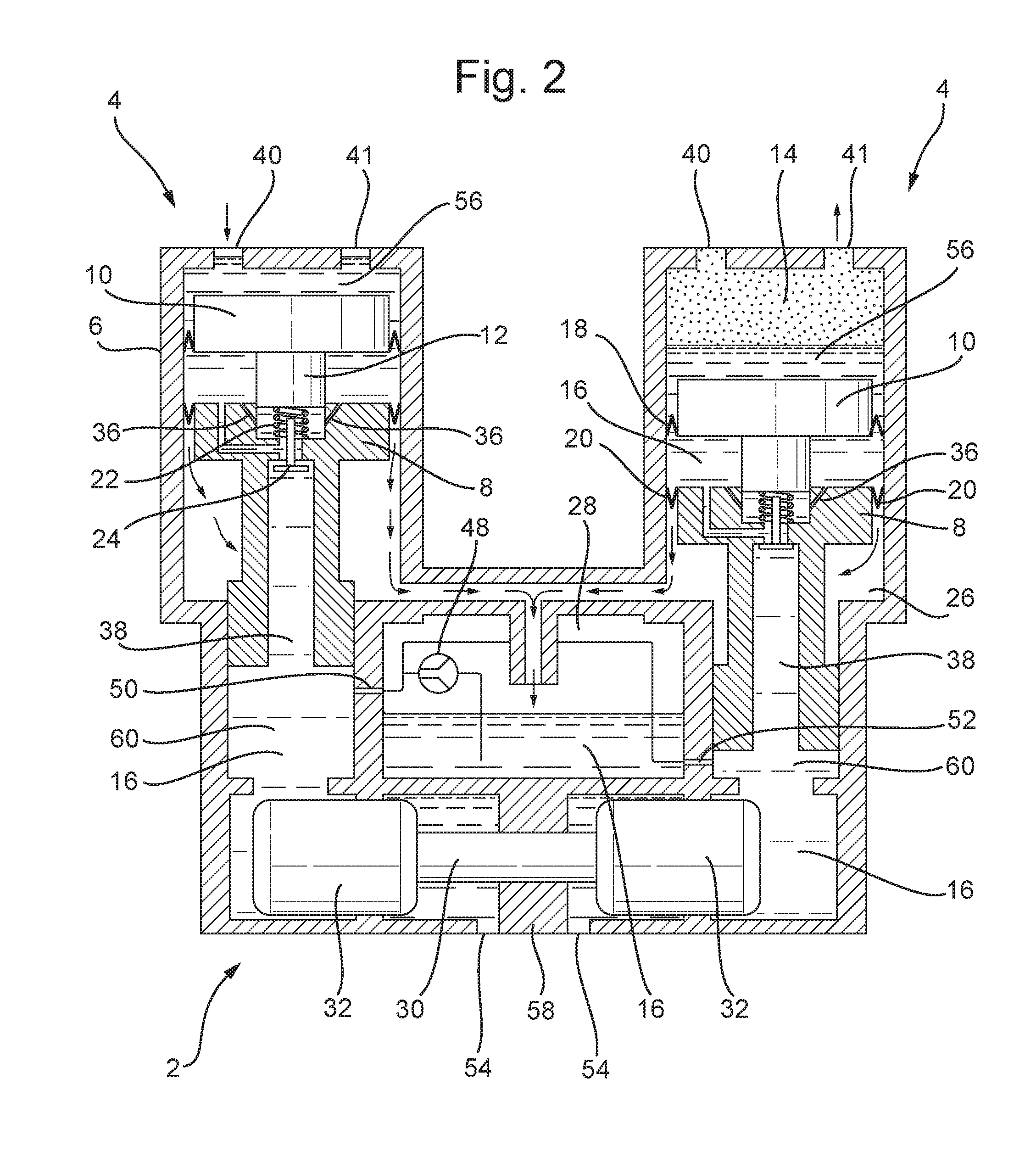
[0052] FIG. 2 is a schematic diagram of a second embodiment of the gas compressor according to the invention having two spaced apart piston compressors (left and right-hand sides) each having a slidably mounted piston assembly. The piston assembly in each compressor uses an ionic liquid cushion thereon, and the piston assembly of the left-hand piston compressor has moved to the top of its cylinder tube, thereby compressing gas therein via the ionic cushion, and the piston assembly of the right-hand piston compressor is positioned towards the middle of its cylinder tube, such that the gas remains substantially uncompressed;
[0053] FIG. 3 is a cross-sectional side view of the compressor shown in FIG. 1, in which the piston assembly of the left-hand piston compressor has moved to the top of its cylinder tube, thereby compressing gas therein, and the piston assembly of the right-hand piston compressor is positioned at the base of its cylinder tube, such that the gas remains uncompressed. Fresh gas is sucked in towards the bottom dead centre;
[0054] FIG. 4 is an enlarged cross-sectional side view of the top of the left-hand piston compressor shown in FIG. 3 with the piston assembly positioned at the top of its cylinder tube having compressed the gas; and
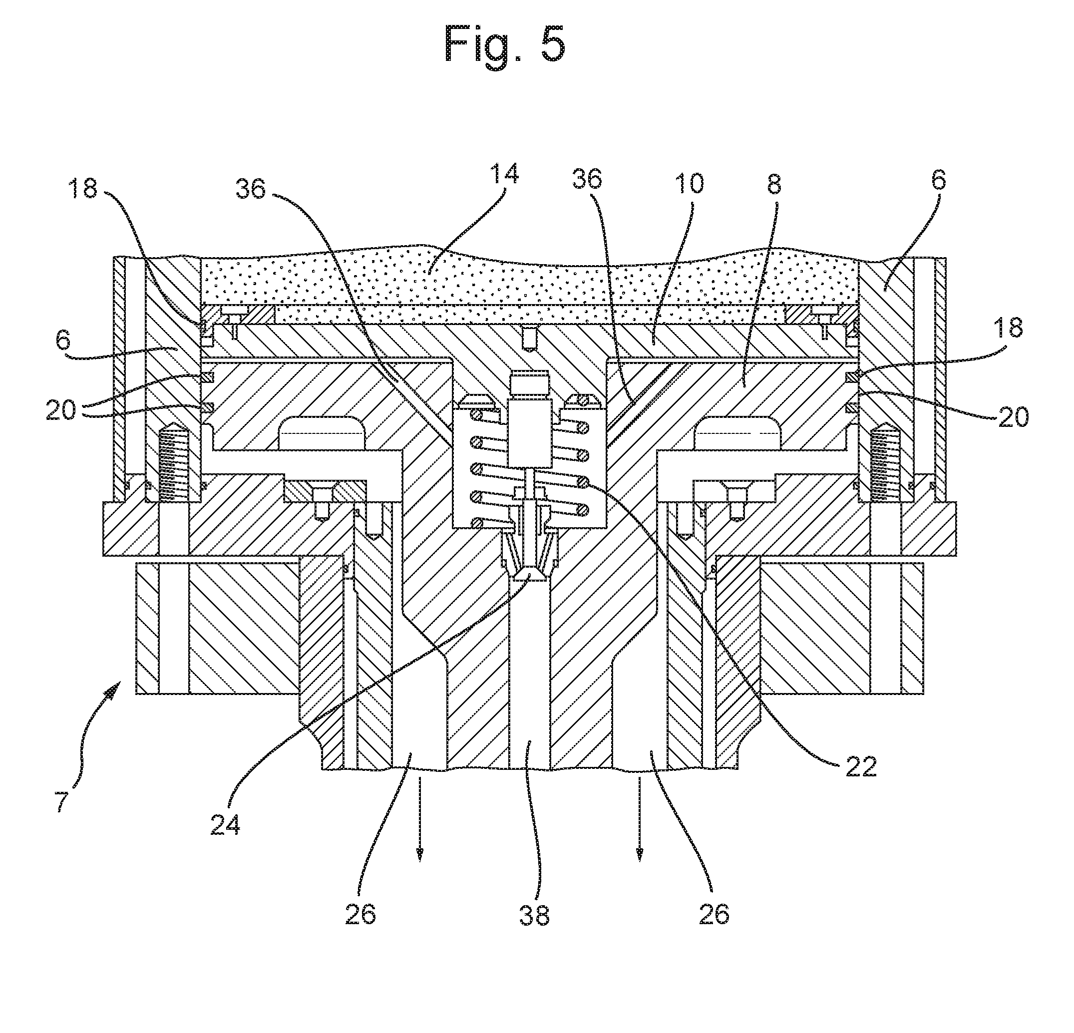
[0055] FIG. 5 is an enlarged cross-sectional side view of one piston assembly of a piston compressor present in the compressor of the invention.
EXAMPLE
[0056] Referring to FIGS. 1-3, there are shown embodiments of a compressor 2 for compressing gas 14, such as natural gas (CNG), fuel gas, hydrogen, gaseous hydrocarbons, liquefied combustion gas, nitrogen, helium, oxygen, and noble gases such as argon. For example, the compressor 2 can be used to compress hydrogen which is used as fuel in hydrogen-driven vehicles. Compression is hydraulically driven, for example by means of an ionic compressor or by a piston compressor, as shown in the Figures. It will be appreciated therefore that the compressor 2 is a liquid piston compressor.
[0057] FIGS. 1 and 2 show first and second embodiments of the compressor 2, respectively. In each embodiment, the compressor 2 includes two, spaced apart piston compressors 4 in parallel, into which uncompressed gas 14 is fed via an inlet 40, and from which compressed gas 14 exits via outlet 41. The pressure of the inlet gas 14 is about 6 Bar, and the pressure of the outlet, compressed gas 14 is about 350 Bar. The inlet 40 and outlet 41 are fitted with multichannel valves 44 with very low frequency expectation values (a compressor frequency 0.1 Hz-5 Hz, more preferably 0.5 Hz-1.5 Hz means low actuating frequencies for the valves as well) to allow the passage of gas 14 therethrough.
[0058] As can be seen in the Figures, the illustrated compressor 2 is a single-stage compressor (i.e. 1-stage). The piston compressors 4 in the illustrated 1-stage system are in parallel and are driven by a single plunger 30 which causes the reciprocal oscillation of pistons 32 connected thereto within a housing 58. Each piston 32 is connected to a corresponding pump 42, which is arranged to displace hydraulic driving fluid 16 disposed in a reservoir 60 to and from its corresponding compressor piston 4, thereby compressing the gas 14 therein.
[0059] However, multi-stage compressors are also envisaged in which at least two of the compressors 2 in FIG. 3 are connected in series, so that the discharge through outlet 41 of both same pressure stage compressors 4 are connected to the suction inlet port 40 of the higher pressure stage. For example, there may be four compressor 2 stages, in which the pressure of the inlet gas 14 into the first compressor 2 is 6 bara, and the pressure of the outlet, compressed gas 14 is 16.6 bara; the pressure of the inlet gas 14 into the second compressor 2 is 16.6 bara, and the pressure of the outlet gas 14 is 45.7 bara; the pressure of the inlet gas 14 into the third compressor 2 is 45.7 bara, and the pressure of the outlet gas 14 is 126 bara; and the pressure of the inlet gas 14 into the fourth compressor 2 is 126 bara, and the pressure of the outlet gas 14 is 350 bara.
[0060] The hydraulic driving fluid 16 is incompressible, and can be any ionic liquid, an LOHC (liquid organic hydrogen carrier), heavy water, deuterium oxide, water, or hydraulic oil, or mixtures thereof. The overall hydraulic system needs to be designed for the lower lubricity of the heavy water, for example, compared to a standard lubricant like oil. Oscillation of the pistons 32 driven by the plunger 30 is facilitated by a lubricant 34 which is fed into the housing 58 via inlets 54. In some embodiments, the lubricant 34 for the plunger 30 may be hydraulic oil 34, LOHC or an ionic liquid, or mixtures thereof. The lubricant 34 should be kept separate from the driving fluid 16 because it needs to have a different compression ratio.
[0061] In FIGS. 2 and 3, the compressor 2 is shown with its left-hand piston compressor 4 in a configuration such that it is compressing the gas 14, and with its right-hand piston compressor 4 in a configuration in which gas 14 remains substantially uncompressed, after fresh gas has been sucked in through suction valve 40. Position sensors 46 connected to each pump 42 detect the configuration of each piston compressor 4, and facilitate respective oscillations therein, such that gas 14 is automatically fed into the piston compressors 4 through inlets 40, and compressed, and then expelled at high pressure through outlets 41.
[0062] In prior art compressors, gas seals disposed the gas being compressed 14 and the pistons are subjected to the full gas pressure, which lead to wear during continued use. However, referring to FIGS. 3 and 4, the compressor 2 of the invention is fitted with a mechanism by which the life-time of gas seals 18 within the piston compressors 4 is significantly extended by reducing wear and tear thereon. As can be seen most clearly in FIG. 5, each piston compressor 4 includes a cylinder tube 6 in which a piston assembly 7 (also known as a "dummy" piston) is slidably mounted. Each piston assembly 7 consists of a floating piston 10 connected to a spaced apart main piston 8. The floating piston 10 is arranged to oscillate within the cylinder tube 6, and is sealed therein by a radial gas seal 18, such as a V-piston ring. One side of the floating piston 10 (i.e. the upper side shown in FIGS. 1, 2 and 5) is in contact with the gas 14 that is to be compressed (e.g. hydrogen, or compressed natural gas, CNG). On its opposite side (i.e. the lower side shown in FIGS. 1, 2 and 5), the floating piston 10 is in contact with a thin layer of the same incompressible hydraulic driving fluid 16, which is displaced by pistons 32 to cause the piston assembly 7 to oscillate within the cyclinder tube 6.
[0063] The floating piston 10 is centrally embedded within the main piston 8, and is guided concentrically thereby. The main piston 8 is also slidably mounted within the cylinder tube 6 and is sealed therewith by a radial hydraulic seal 20, such as a V-piston ring. The incompressible hydraulic driving fluid 16 disposed in the space between the floating piston 10 and the main piston 8 is fluidly connected, via a duct 26 along which any leaked hydraulic fluid through seal 20 is fed, to a storage tank 28 in which replenishment hydraulic driving fluid 16 is stored, which is shown in FIGS. 1 and 2.
[0064] Referring to FIG. 5, the storage tank 28 creates a leakage cycle return line to the space between the pistons 8, 10, because, during use of the compressor piston 4, any leak of hydraulic driving fluid 16 at the hydraulic seal 20 can be automatically balanced out by a replenishment flow of driving fluid 16, as follows. The main piston 8 has a hydraulic fluid replenishment feed valve 24, which is fluidly connected by conduits 38, 50 to the storage tank 28. The valve 24 is biased into a closed position by a helical spring 22 or a cup spring 22 acting thereon. However, if the pressure on the gas side of the first seal 18 increases due to leakage of driving fluid 16 through seal 20, the floating piston 10 is urged towards the main piston 8, resulting in the replenishment feed system being activated via an actuating unit 12 connected to the valve 24. The valve 24 is opened by the actuating unit 12, and hydraulic fluid 16 is pumped by pump 48 from the storage tank 28 along conduits 50, 38, through the open valve 24, and along diagonal conduits 36, which lead directly into the space between the main piston 8 and the floating piston 10. Accordingly, a constant depth of hydraulic driving fluid 16 is maintained between the floating piston 10 and main piston 8. The replacement driving fluid 16 can be pumped back into the space between the floating piston 10 and main piston 8 at any stage in the process. However, in the embodiment shown in the Figures, the pump 48 is activated when the piston assembly 7 is disposed at the bottom of the cylinder tube 6, i.e. the non-compression stage.
[0065] The pressure between the gas side of the floating piston 10 and the incompressible hydraulic fluid 16 is designed to be constantly balanced out. The spring's 22 pre-stress tension on the actuating unit 12 corresponds to the weight of the floating piston 10 and the friction created between the cylinder tube 6 and the gas seal 18. The pressure difference between the side of the floating piston 10 contacting the gas 14, and the side contacting the hydraulic fluid 16 is less than 2 Bar, and small radial forces between the floating piston 10 and the seal 18 results in less wear and tear.
[0066] The system described above therefore always attempts to subject the first gas seal 18 only to the pre-tension pressure that is defined by the seal 18, in order to minimise wear on the seal 18. In prior art compressors, the gas seal in contact with the compressed gas 14 is exposed to a pressure equivalent to the gas pressure, which causes wear, whereas by splitting the piston assembly 7 into two (i.e. the floating piston 10 and the main piston 8), the gas seal 18 in the compressor 2 of the invention is exposed to a reduced pressure of only 2 bar. Hence, the invention results in the significant reduction of load on the gas seal 18. Although the hydraulic seal 20 is exposed to the similar pressures to that experienced in the prior art compressor, it does not affect the system as a whole because any leakage of hydraulic fluid 16 is immediately re-injected back into the space between the pistons 10, 12 along conduits 36 from storage tank 28.
[0067] The embodiment of the compressor 2 shown in FIG. 3 is essentially the same as that shown in FIG. 2 except that, in FIG. 3, an ionic liquid cushion 56 is provided in between the piston assembly 7 and the gas 14 being compressed. This is useful in embodiments when the hydraulic driving fluid 16 is itself an ionic liquid, and may not be necessary when the driving fluid 16 is an LOHC. The ionic liquid cushion 56 is on top of the floating piston 10 and fills out all of the dead space whilst in the compression phase. The ionic liquid cushion 56 comprises a fluid with a low vapour pressure, and can be made up of any pure ionic liquid, or a mixture of ionic liquid and LOHC.
[0068] Advantages of the compressor 2 reside in extended wear time for the piston seals 18, 20 (>20.000 h), due to very good lubrication created between the pistons 8, 10 and the cylinder tube 6. This provides excellent corrosion protection, and mechanical protection against compressor knocking, and so results in low noise emission. Further advantages include longer service lives leading to lower maintenance costs. This results in increases plant availability, and lower requirements on the opposite contact face because of lower contact pressure forces, which again, minimises maintenance costs.
* * * * *
D00000
D00001
D00002
D00003
D00004
D00005
XML
uspto.report is an independent third-party trademark research tool that is not affiliated, endorsed, or sponsored by the United States Patent and Trademark Office (USPTO) or any other governmental organization. The information provided by uspto.report is based on publicly available data at the time of writing and is intended for informational purposes only.
While we strive to provide accurate and up-to-date information, we do not guarantee the accuracy, completeness, reliability, or suitability of the information displayed on this site. The use of this site is at your own risk. Any reliance you place on such information is therefore strictly at your own risk.
All official trademark data, including owner information, should be verified by visiting the official USPTO website at www.uspto.gov. This site is not intended to replace professional legal advice and should not be used as a substitute for consulting with a legal professional who is knowledgeable about trademark law.