Piston And Engine Provided With The Same
YU; Seungeun
U.S. patent application number 15/829122 was filed with the patent office on 2019-01-31 for piston and engine provided with the same. This patent application is currently assigned to HYUNDAI MOTOR COMPANY. The applicant listed for this patent is HYUNDAI MOTOR COMPANY, KIA MOTORS CORPORATION. Invention is credited to Seungeun YU.
| Application Number | 20190032596 15/829122 |
| Document ID | / |
| Family ID | 65003960 |
| Filed Date | 2019-01-31 |


| United States Patent Application | 20190032596 |
| Kind Code | A1 |
| YU; Seungeun | January 31, 2019 |
PISTON AND ENGINE PROVIDED WITH THE SAME
Abstract
A piston and an engine including the same are provided. The piston includes an upper surface that is formed at an upper portion; a bowl that is concavely formed at the upper surface; a plurality of protruding portions that are separated by a predetermined distance along an edge of the bowl; and a central portion that is protruded upward at the center of the bowl.
| Inventors: | YU; Seungeun; (Bucheon-si, KR) | ||||||||||
| Applicant: |
|
||||||||||
|---|---|---|---|---|---|---|---|---|---|---|---|
| Assignee: | HYUNDAI MOTOR COMPANY Seoul KR KIA MOTORS CORPORATION Seoul KR |
||||||||||
| Family ID: | 65003960 | ||||||||||
| Appl. No.: | 15/829122 | ||||||||||
| Filed: | December 1, 2017 |
| Current U.S. Class: | 1/1 |
| Current CPC Class: | F02B 23/0672 20130101; F02F 3/24 20130101; F02B 23/0696 20130101 |
| International Class: | F02F 3/24 20060101 F02F003/24 |
Foreign Application Data
| Date | Code | Application Number |
|---|---|---|
| Jul 28, 2017 | KR | 10-2017-0095873 |
Claims
1. A piston, comprising: an upper surface that is formed at an upper portion; a bowl that is concavely formed at the upper surface; a plurality of protruding portions that are separated by a predetermined distance along an edge of the bowl; and a central portion that is protruded upward at the center of he bowl.
2. The piston of claim I, wherein the each protruding portion comprises: a first guide surface that is inclined to flow the fuel in one direction; and a second guide surface that is inclined in an opposite direction of the first guide surface, wherein a cross-section slope of a first guide surface of a vertical direction of the piston is more gently than that of a second guide surface of a vertical direction of the piston.
3. The piston of claim 2, wherein a recess portion for guiding upward fuel that is moved along the first guide surface is formed between the each protruding portion.
4. The piston of claim 3, wherein at a boundary of the bowl and the upper surface, a protruding portion lip corresponding to the protruding portion and a recess portion lip corresponding to the recess portion are formed, but a length from the center of the bowl to the protruding portion lip is longer than that from the center of the bowl to the recess portion lip.
5. The piston of claim 4, wherein a length from the center of the bowl to the protruding portion lip is 0.95 times to 1.0 times larger than that from the center of the bowl to an uppermost portion of the protruding portion.
6. The piston of claim 4, wherein a length from the center of the bowl to the recess portion lip is 0.8 times to 0.9 times larger than that from the center of the bowl to an endmost portion of the recess portion.
7. The piston of claim 4, wherein a height of the recess portion lip is 1.5 times or less larger than that of the protruding portion lip.
8. An engine, comprising: an injector in which a plurality of injector holes are radially and downwardly formed; and a piston in which a plurality of protruding portions are formed to flow in one direction fuel that is ejected from the injector hole.
9. The engine of claim 8, wherein the each protruding portion comprises: a first guide surface that is inclined to flow the fuel in one direction; and a second guide surface that is inclined in an opposite direction of the first guide surface, a cross-section slope of a first guide surface of a vertical direction of the piston is more gently than a cross-section slope of a second guide surface of a vertical direction of the piston.
10. The engine of claim 9, wherein at the piston head, an upper surface is formed, and a bowl is formed concavely from the upper surface, and the each protruding portion is separated by a predetermined distance along an edge of the bowl.
11. The engine of claim 10, wherein a recess portion for guiding upward fuel that is moved along the first guide surface is formed between the each protruding portion.
12. The engine of claim 11, wherein at a boundary of the bowl and the upper surface, a protruding portion lip corresponding to the protruding portion and a recess portion lip corresponding to the recess portion are formed, but a length from the center of the bowl to the protruding portion lip is longer than that from the center of the bowl to the recess portion lip.
13. The engine of claim 11 wherein a length from the center of the bowl to the protruding portion lip is 0.95 times to 1.0 times larger than that from the center of the bowl to an uppermost portion of the protruding portion.
14. The engine of claim 11, wherein a length from the center of the bowl to the recess portion lip is 0.8 times to 0.9 times larger than that from the center of the bowl to an endmost portion of the recess portion.
15. The engine of claim 8, wherein a height of the recess portion lip is 1.5 times or less larger than that of the protruding portion lip.
Description
CROSS-REFERENCE TO RELATED APPLICATION
[0001] This application claims priority to and the benefit of Korean Patent Application No. 10-2017-0095873 filed in the Korean Intellectual Property Office on Jul. 28, 2017, the entire contents of which are incorporated herein by reference.
BACKGROUND
(a) Field
[0002] The present disclosure relates to a piston and an engine including the same. More particularly, the present invention relates to a piston and an engine including the same that reduce fuel spray and flame overlapping.
(b) Description of the Related Art
[0003] Fuel that is ejected to a combustion chamber according to a driving condition of a vehicle may be ejected in various forms.
[0004] However, fuel spray and flame overlapping may occur according to a vehicle driving condition, and in a portion in which fuel or flame are overlapped, particulate matters (PM) occur.
[0005] Such PM occurrence may be replaced with PM reduction mapping, but when using PM reduction mapping, fuel consumption may be deteriorated.
[0006] Further, there is a method of mixing air/fuel using a swirl port, but a movement resistance may occur with application of the swirl port, and volume efficiency may be deteriorated due to intake resistance.
[0007] The above information disclosed in this Background section is only for enhancement of understanding of the background of the invention and therefore it may contain information that does not form the prior art that is already known in this country to a person of ordinary skill in the art.
[0008] The disclosure of this section is to provide background of the invention. Applicant notes that this section may contain information available before this application. However, by providing this section, Applicant does not admit that any information contained in this section constitutes prior art.
SUMMARY
[0009] The present invention has been made in an effort to further provide a piston and an engine including the same having advantages of being capable of reducing intake resistance through a guide shape of sprayed fuel.
[0010] An embodiment of the present invention provides a piston including an upper surface that is formed at an upper portion; a bowl that is concavely formed at the upper surface; a plurality of protruding portions that are separated by a predetermined distance along an edge of the bowl; and a central portion that is protruded upward at the center of the bowl.
[0011] The each protruding portion may include a first guide surface that is inclined to flow the fuel in one direction; and a second guide surface that is inclined in an opposite direction of the first guide surface, wherein a cross-section slope of a first guide surface of a vertical direction of the piston may be more gently than that of a second guide surface of a vertical direction of the piston.
[0012] A recess portion for guiding upward fuel that is moved along the first guide surface may be formed between the each protruding portion.
[0013] At a boundary of the bowl and the upper surface, a protruding portion lip corresponding to the protruding portion and a recess portion lip corresponding to the recess portion may be formed, but a length from the center of the bowl to the protruding portion lip may be longer than that from the center of the bowl to the recess portion lip.
[0014] A length from the center of the bowl to the protruding portion lip may be 0.95 times to 1.0 times larger than that from the center of the bowl to an uppermost portion of the protruding portion.
[0015] A length from the center of the bowl to the recess portion lip may be 0.8 times to 0.9 times larger than that from the center of the bowl to an endmost portion of the recess portion.
[0016] A height of the recess portion lip may be 1.5 times or less larger than that of the protruding portion lip.
[0017] Another embodiment of the present invention provides an engine including an injector in which a plurality of injector holes are radially and downwardly formed; and a piston in which a plurality of protruding portions are formed to flow in one direction fuel that is ejected from the injector hole.
[0018] The each protruding portion may include a first guide surface that is inclined to flow the fuel in one direction; and a second guide surface that is inclined in an opposite direction of the first guide surface, but a cross-section slope of a first guide surface of a vertical direction of the piston may be more gently than that of a second guide surface of a vertical direction of the piston.
[0019] At the piston head, an upper surface may be formed, and a bowl may be formed concavely from the upper surface, and the each protruding portion may be separated by a predetermined distance along an edge of the bowl.
[0020] A recess portion for guiding upward fuel that is moved along the first guide surface may be formed between the each protruding portion.
[0021] At a boundary of the bowl and the upper surface, a protruding portion lip corresponding to the protruding portion and a recess portion lip corresponding to the recess portion may be formed, but a length from the center of the bowl to the protruding portion lip may be longer than that from the center of the bowl to the recess portion lip.
[0022] A length from the center of the bowl to the protruding portion lip may be 0.95 times to 1.0 times larger than that from the center of the bowl to an uppermost portion of the protruding portion.
[0023] A length from the center of the bowl to the recess portion lip may be 0.8 times to 0.9 times larger than that from the center of the bowl to an endmost portion of the recess portion.
[0024] A height of the recess portion lip may be 1.5 times or less larger than that of the protruding portion lip.
[0025] By a piston and an engine including the same according to an embodiment of the present invention, fuel spray and flame overlapping can be avoided.
[0026] Further, by a piston and an engine including the same according to an embodiment of the present invention, intake resistance can be reduced through a guide shape of sprayed fuel.
BRIEF DESCRIPTION OF THE DRAWINGS
[0027] FIG. 1 is a partially cross-sectional view of an engine including a piston according to an embodiment of the present invention.
[0028] FIG. 2 is a top plan view of a piston according to an embodiment of the present invention.
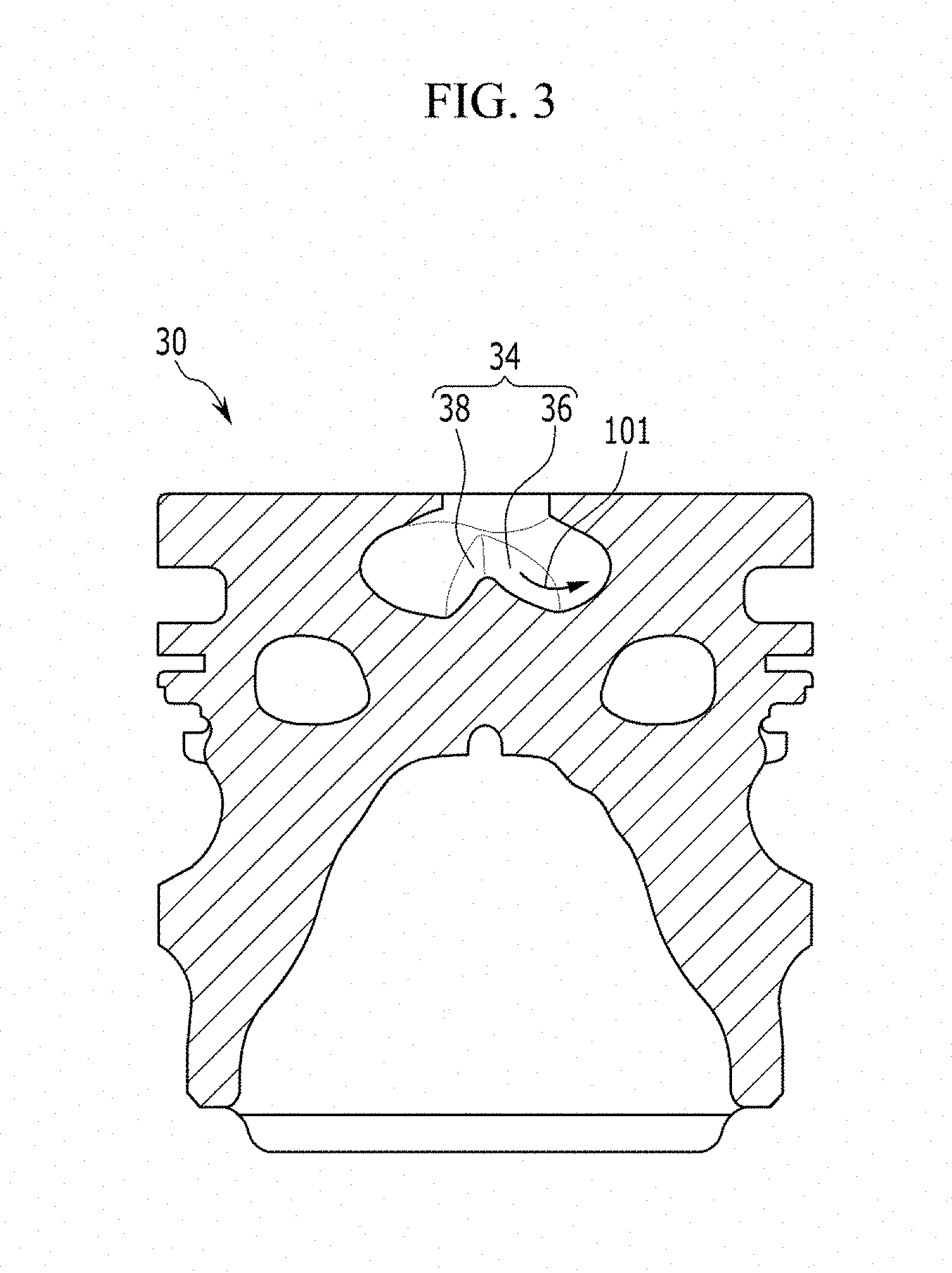
[0029] FIG. 3 is a cross-sectional view of the piston taken along line III-III of FIG. 2.
[0030] FIG. 4 is a cross-sectional view of the piston taken along line IV-IV of FIG. 2.
[0031] FIG. 5 is a cross-sectional view of the piston taken along line V-V of FIG. 2.
DETAILED DESCRIPTION
[0032] In the following detailed description, embodiments of the present invention have been shown and described, simply by way of illustration..
[0033] As those skilled in the art would realize, the described embodiments may be modified in various different ways, all without departing from the spirit or scope of the present invention
[0034] Like reference numerals designate like elements throughout the specification.
[0035] In the drawings, the thickness of layers, films, panels, regions, etc., may be exaggerated for clarity.
[0036] When it is said that any part, such as a layer, film, region, or plate, is positioned on another part, it means the part is directly on the other part or above the other part with at least one intermediate part.
[0037] In contrast, when an element is referred to as being "directly on" another element, there are no intervening elements present.
[0038] In addition, in the specification, unless explicitly described to the contrary, the word "comprise" and variations such as "comprises" or "comprising", will be understood to imply the inclusion of stated elements but not the exclusion of any other elements.
[0039] Embodiments of the present invention will hereinafter be described in detail with reference to the accompanying drawings.
[0040] According to an aspect of the invention, a vehicle engine including a piston head that has a recess at its top surface is disclosed. The pistol head has a top flat surface facing a fuel sprayer 70, 72 inside a cylinder of a vehicle engine 10. The piston head 30 includes a recess 50 formed at a central portion of the top flat surface. Inside the recess, the piston head has a central protrusion 40 protruding toward the fuel sprayer. When viewed over the top, a plurality of peripheral protrusions 34 are formed inside the recess around the central protrusion 40 for guiding fuel injected into the recess. As each of the peripheral protrusions 40 is not in a symmetrical shape and has two top surfaces 36, 38 slanted in different angles against an axis of piston movement, flow of fuel from the fuel sprayer 72 form a swirl inside the recess when view over the top as illustrated in FIG. 2.
[0041] A symmetrical shape of the peripheral protrusions 40 cause a tumble flow of the fuel from bottom of the recess toward the opening of the recess along a side wall of the recess for reducing overlapping of fuel spray and flame over the piston head.
[0042] FIG. 1 is a partially cross-sectional view of an engine including a piston according to an embodiment of the present invention, and FIG. 2 is a top plan view of a piston according to an embodiment of the present invention,
[0043] FIG. 3 is a cross-sectional view of the piston taken along line III-III of FIG. 2, FIG. 4 is a cross-sectional view of the piston taken along line IV-IV of FIG. 2, and FIG. 5 is a cross-sectional view of the piston taken along line V-V of FIG. 2.
[0044] Referring to FIGS. 1 to 5, an engine 10 according to an embodiment of the present invention includes an injector 70 in which a plurality of injector holes 72 are radially and downwardly formed and a piston 30 in which a plurality of protruding portions 34 are formed to flow in one direction fuel that is ejected from the injector hole 72.
[0045] The piston 30 according to an embodiment of the present invention may include an upper surface 32 that is formed in an upper portion, a bowl 50 that is concavely formed at the upper surface, and a central portion 40 that is protruded upward at the center of the bowl 50, and the plurality of protruding portions 34 are separated by a predetermined distance along an edge of the bowl 50.
[0046] As shown in FIG. 3, the each protruding portion 34 includes a first guide surface 36 that is inclined to flow the fuel 101 in one direction and a second guide surface 38 that is inclined in an opposite direction of the first guide surface 36. A cross-section slope of the first guide surface 36 of a vertical direction of the piston 30 may be more gently than that of the second guide surface 38 of a vertical direction of the piston 30.
[0047] As shown in FIGS. 1 and 2, fuel is ejected from the each injector hole 72 toward each protruding portion 34, and the ejected fuel 101 is guided and flowed along the first guide surface 36. The ejected fuel may flow clockwise based on an upper portion of the piston 30, as shown in FIG. 2, but it is not limited thereto and the ejected fuel may be inducted counterclockwise according to a forming direction of the first guide surface 36,
[0048] It is shown that 8 protruding portions 34 are formed to correspond to ejecting injector holes, but the present invention is not limited thereto and various numbers of protruding portions may be formed to correspond to the formed injector holes.
[0049] Smooth swirl of ejected fuel 101 is available according to guide of ejection fuel by the protruding portion 34, and ejected fuel 101 can be prevented from being overlapped.
[0050] By swirl by the protruding portion 34, an additional swirl forming at an intake port would be unnecessary, and thus intake efficiency may be increased.
[0051] A recess portion 80 for guiding upward fuel that is moved along the first guide surface 36 may be formed between the each protruding portion 34.
[0052] At a boundary of the bowl 50 and the upper surface 32, a protruding portion lip 60 corresponding to the protruding portion 34 and a recess portion lip 62 corresponding to the recess portion 80 are formed.
[0053] The protruding portion lip 60 and the recess portion lip 62 may be defined to a constant plane that contacts the upper surface 32.
[0054] A length L1 from the center X of the bowl 50 to the protruding portion lip 60 may be longer than a length L3 from the center X of the bowl 50 to the recess portion lip 62,
[0055] A length L1 from the center X of the bowl 50 to the protruding portion lip 60 may be 0.95 times and 1.0 times larger than a length L2 from the center X of the bowl 50 to an uppermost end 39 of the protruding portion 34.
[0056] A length L3 from the center X of the bowl 50 to the recess portion lip 62 may be 0.8 times and 0.9 times larger than a length L4 from the center X of the bowl 50 to an endmost portion 82 of the recess portion 80.
[0057] A height h1 of the recess portion lip 62 may be 1.5 times or less larger than a height h2 of the protruding portion lip 60.
[0058] Fuel 101 that is ejected to the each protruding portion 34 is moved along the first guide surface 36, rotates along the round-shaped recess portion 80, and moves again along the second guide surface 38.
[0059] Because a cross-section slope of the second guide surface 38 of a vertical direction of the piston 30 is formed more sharply than that of the first guide surface 36 of a vertical direction of the piston 30, fuel 102 that is rotated along the recess portion 80 may move upward along the second guide surface 38.
[0060] A tumble movement may be reinforced by a shape of the central portion 40, the protruding portion lip 60 and the recess portion lip 62.
[0061] That is, by a shape of the protruding portion 34, the recess portion 80, the central portion 40, the protruding portion lip 60, and the recess portion lip 62, a swirl movement (referring to 101 in FIG. 2) and a tumble movement (referring to 102 in FIG. 102) may be reinforced.
[0062] As described above, by a piston and an engine according to an embodiment of the present invention, fuel spray and flame overlapping can be avoided and intake resistance can be reduced.
[0063] While this invention has been described in connection with embodiments of the present invention, it is to be understood that the invention is not limited to the disclosed embodiments. On the contrary, it is intended to cover various modifications and equivalent arrangements included within the spirit and scope of the appended claims.
DESCRIPTION OF SYMBOLS
TABLE-US-00001 [0064] 10: engine 30: piston 32: upper surface 34: protruding portion 36: first guide surface 38: second guide surface 40: central portion 50: bowl 60: protruding portion lip 62: recess portion lip 70: injector 72: injector hole 80: recess portion
* * * * *
D00000
D00001
D00002
D00003
D00004
D00005
XML
uspto.report is an independent third-party trademark research tool that is not affiliated, endorsed, or sponsored by the United States Patent and Trademark Office (USPTO) or any other governmental organization. The information provided by uspto.report is based on publicly available data at the time of writing and is intended for informational purposes only.
While we strive to provide accurate and up-to-date information, we do not guarantee the accuracy, completeness, reliability, or suitability of the information displayed on this site. The use of this site is at your own risk. Any reliance you place on such information is therefore strictly at your own risk.
All official trademark data, including owner information, should be verified by visiting the official USPTO website at www.uspto.gov. This site is not intended to replace professional legal advice and should not be used as a substitute for consulting with a legal professional who is knowledgeable about trademark law.