Floor Faucet Structure
Hsieh; Ming-Chun ; et al.
U.S. patent application number 15/661301 was filed with the patent office on 2019-01-31 for floor faucet structure. The applicant listed for this patent is HORNG LAI INDUSTRIAL CO., LTD.. Invention is credited to Chia-Yi Hsieh, Ming-Chun Hsieh.
| Application Number | 20190032308 15/661301 |
| Document ID | / |
| Family ID | 65138153 |
| Filed Date | 2019-01-31 |


| United States Patent Application | 20190032308 |
| Kind Code | A1 |
| Hsieh; Ming-Chun ; et al. | January 31, 2019 |
Floor Faucet Structure
Abstract
A floor faucet structure contains: a body, an adjustable fitting sleeve, a fixing seat, and a connection sleeve. The body includes a positioning disc having multiple orifices. The body further includes a cold-water inlet tube and a hot-water inlet, the two rotation members connect with two connectors individually, and the two connectors are perpendicular to the cold-water inlet tube and the hot-water inlet tube separately. The adjustable fitting sleeve includes a first coupling portion, the fixing seat includes a circular groove having multiple through holes, and the fixing seat includes multiple retaining ribs. The connection sleeve includes a second coupling portion configured to connect with the first coupling portion of the body, and the connection sleeve also includes a cylindrical fence on which two opposite cutouts are formed. The connection sleeve further includes multiple locking ribs configured to retain with the multiple retaining ribs of the fixing seat respectively.
| Inventors: | Hsieh; Ming-Chun; (CHANG HUA HSIEN, TW) ; Hsieh; Chia-Yi; (CHANG HUA HSIEN, TW) | ||||||||||
| Applicant: |
|
||||||||||
|---|---|---|---|---|---|---|---|---|---|---|---|
| Family ID: | 65138153 | ||||||||||
| Appl. No.: | 15/661301 | ||||||||||
| Filed: | July 27, 2017 |
| Current U.S. Class: | 1/1 |
| Current CPC Class: | E03C 1/042 20130101; E03C 1/04 20130101; E03C 1/0403 20130101; E03C 1/021 20130101 |
| International Class: | E03C 1/02 20060101 E03C001/02; E03C 1/04 20060101 E03C001/04 |
Claims
1. A floor faucet structure comprising: a body being an upright pipe and including a positioning disc disposed on a bottom of the body, and the positioning disc having multiple orifices, the body further including a cold-water inlet tube and a hot-water inlet which are accommodated in the body, and lower ends of the cold-water inlet tube and the hot-water inlet tube extending out of the body so as to connect with two rotation members respectively, wherein the two rotation members connect with two connectors individually, and the two connectors are perpendicular to the cold-water inlet tube and the hot-water inlet tube separately; an adjustable fitting sleeve being slidably fitted in the bottom of the body, and the adjustable fitting sleeve including a first coupling portion formed on a lower end of the adjustable fitting sleeve and extending outside an outer wall of the body; a fixing seat including a circular groove defined on a top of the fixing seat, and the circular groove having multiple through holes formed in the circular groove, the fixing seat also including a plurality of retaining ribs arranged on a peripheral wall of the circular groove; and a connection sleeve including a second coupling portion arranged on an upper end of the connection sleeve so as to connect with the first coupling portion of the body, the connection sleeve also including a cylindrical fence on which two opposite cutouts are formed, such that the two rotation members and the two connectors extend out of the two opposite cutouts respectively, and the connection sleeve further including multiple locking ribs arranged on a lower end thereof and configured to retain with the plurality of retaining ribs of the fixing seat respectively.
2. The floor faucet structure as claimed in claim 1 further comprising a cap slidably fitted with the outer wall of the body and configured to cover on the positioning disc.
3. The floor faucet structure as claimed in claim 1, wherein the body further includes a control handle and an outlet tube which are mounted on a top of the body.
4. The floor faucet structure as claimed in claim 1, wherein the first coupling portion is outer threads, and the second coupling portion is inner threads.
5. The floor faucet structure as claimed in claim 1, wherein a cross section of the adjustable fitting sleeve is circular.
Description
BACKGROUND OF THE INVENTION
Field of the Invention
[0001] The present invention relates to a faucet structure, and more particularly to a floor faucet structure which is mounted beside an independent bathtub so as to limit water supply and to couple with a shower head.
Description of the Prior Art
[0002] A conventional floor faucet is mounted beside an independent bathtub, as shown in FIGS. 1 and 2. The conventional floor faucet contains: a body 91, a fixing seat 92, a connection sleeve 93, and a cap 94. The body 91 includes a control handle 911 and an outlet tube 12 which are mounted on a top of the body 91, and the body 91 also includes inner threads 913 formed on an inner wall of a bottom thereof, a positioning disc 914 connected on an outer wall of the bottom of the body 91, three orifices 915 formed on the positioning disc 914, and a cold-water inlet tube 916 and a hot-water inlet tube 917 which are accommodated in and extend out of the body 91. The fixing seat 92 is a circular disk and includes a circular groove 921 defined on a top thereof, three through holes 922 formed in the circular groove 921, and two opposite retaining ribs 923 extending outwardly from a peripheral wall of the circular groove 921. The connection sleeve 93 includes outer threads 931 formed on an upper end thereof, a cylindrical fence 932, and two opposite cutouts 933 arranged on the cylindrical fence 932, such that the cold-water inlet tube 916 and the hot-water inlet tube 917 insert through the two opposite cutouts 933 individually. The connection sleeve 93 further includes two locking ribs 934 extending outwardly from a lower end thereof, and the cap 94 is slidably fitted on the body 91.
[0003] As desiring to fix the conventional floor faucet, an affix aperture A2 is drilled on a predetermined position of a floor A1, the fixing seat 92 is fixed on a ground B1 below the affix aperture A2, and at least one first screw bolt 95 is screwed with the outer threads 931 of the connection sleeve 93 and the inner threads 913 of the body 91 via the three through holes 922 of the fixing seat 92. Thereafter, the at least one first screw bolt 95 is inserted and rotated in the circular groove 921 of the fixing seat 92 through the affix aperture A2 of the floor A1, hence the two locking ribs 934 of the connection sleeve 93 retain with the two retaining ribs 923 of the fixing seat 92 so that the connection sleeve 93 is mounted on the fixing seat 92. The positioning disc 914 contacts with the floor A1, and multiple second screw bolts 96 are screwed in the ground B1 via the three orifices 915 of the positioning disc 914, and the cap 94 is covered on the positioning disc 94, thus connecting the conventional floor faucet.
[0004] However, a distance between the positioning disc 914 and the fixing seat 92 is fixed and is applicable for the floor A1 of a single height. When the height of the floor A1 increases, the positioning disc 914 cannot contact with the floor A1 after the bottom of the body 91 is connected with the fixing seat 92 on the ground B1 by using the connection sleeve 93. When the height of the floor A1 decreases, the positioning disc 914 is connected on the outer wall of the bottom of the body 91, so the body 91 cannot insert below the floor A1, and the connection sleeve 93 is too short to connect with the circular groove 921 of the fixing seat 92. In addition, the cold-water inlet tube 916 and the hot-water inlet tube 917 of the body 91 are bent at 90 degrees and extend out of the two opposite cutouts 933 of the connection sleeve 93 separately, so the cold-water inlet tube 916 and the hot-water inlet tube 917 vibrate easily while water flows therein and constantly friction with the opposite cutouts 933 after a period of using time, thus maintaining and replacing the cold-water inlet tube 916 and the hot-water inlet tube 917 frequently and having consumptions of labor force, related components, and time. Likewise, two bending portions C1 of the cold-water inlet tube 916 and the hot-water inlet tube 917 deform easily to influence water flow.
[0005] The present invention has arisen to mitigate and/or obviate the afore-described disadvantages.
SUMMARY OF THE INVENTION
[0006] The primary objective of the present invention is to provide a floor faucet structure in which an adjustable fitting sleeve is slidably fitted in a bottom of a body, and the adjustable fitting sleeve is connected with a connection sleeve, such that the connection sleeve is adjustably moved relative to the body so as to obtain a desired height correspond to various floors.
[0007] Another objective of the present invention is to provide a floor faucet structure in which the body includes a cold-water inlet tube and a hot-water inlet which are accommodated in the body, and lower ends of the cold-water inlet tube and the hot-water inlet tube extend out of the body so as to connect with two rotation members respectively, wherein the two rotation members connect with two connectors individually, and the two rotation members and the two connectors extend out of two opposite cutouts of the connection sleeve respectively, hence the cold-water inlet tube and the hot-water tube do not respectively friction and damage the two opposite cutouts, when water flows in the cold-water inlet tube and the hot-water tube greatly, thus saving maintenance, replacement, and labor costs, reducing installation time, avoiding deformation of the cold-water tube and the hot-water tube, and maintaining water flow.
[0008] To achieve above-mentioned objectives, a floor faucet structure provided by the present invention contains: a body, an adjustable fitting sleeve, a fixing seat, and a connection sleeve.
[0009] The body is an upright pipe and includes a positioning disc disposed on a bottom of the body, and the positioning disc has multiple orifices. The body further includes a cold-water inlet tube and a hot-water inlet which are accommodated in the body, and lower ends of the cold-water inlet tube and the hot-water inlet tube extend out of the body so as to connect with two rotation members respectively, wherein the two rotation members connect with two connectors individually, and the two connectors are perpendicular to the cold-water inlet tube and the hot-water inlet tube separately.
[0010] The adjustable fitting sleeve is slidably fitted in the bottom of the body, and the adjustable fitting sleeve includes a first coupling portion formed on a lower end of the adjustable fitting sleeve and extending outside an outer wall of the body.
[0011] The fixing seat includes a circular groove defined on a top of the fixing seat, and the circular groove has multiple through holes formed in the circular groove, the fixing seat also includes a plurality of retaining ribs arranged on a peripheral wall of the circular groove.
[0012] The connection sleeve includes a second coupling portion arranged on an upper end of the connection sleeve so as to connect with the first coupling portion of the body, and the connection sleeve also includes a cylindrical fence on which two opposite cutouts are formed, such that the two rotation members and the two connectors extend out of the two opposite cutouts respectively. The connection sleeve further includes multiple locking ribs arranged on a lower end thereof and configured to retain with the plurality of retaining ribs of the fixing seat respectively.
BRIEF DESCRIPTION OF THE DRAWINGS
[0013] FIG. 1 is a perspective view showing the exploded components of a conventional floor faucet.
[0014] FIG. 2 is a cross section view showing the operation of the conventional floor faucet structure.
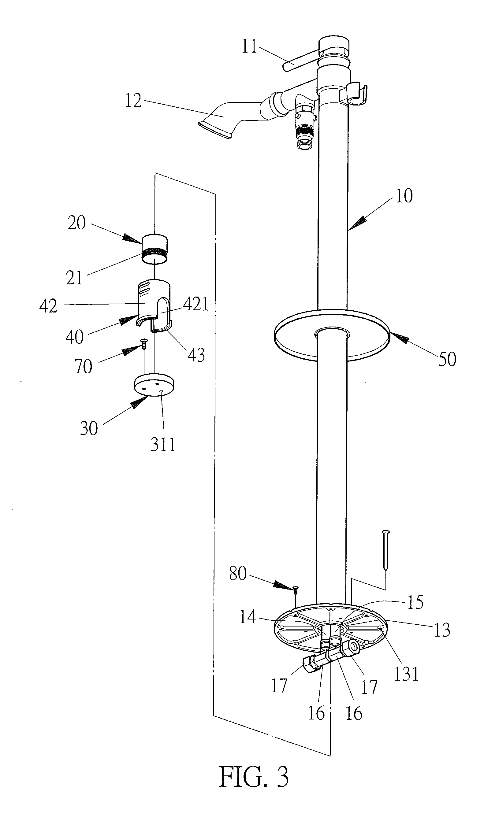
[0015] FIG. 3 is a perspective view showing the exploded components of a floor faucet structure according to a preferred embodiment of the present invention.
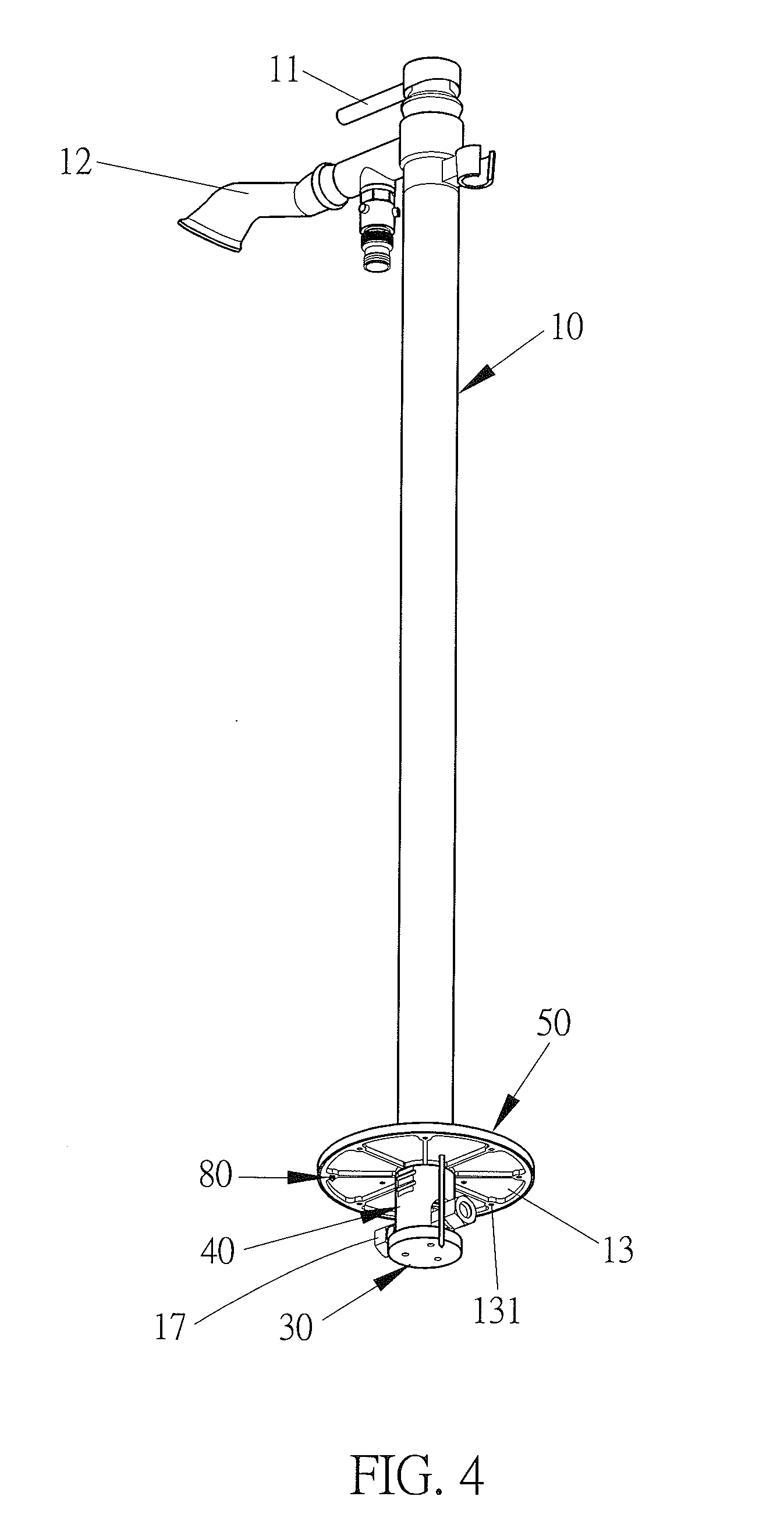
[0016] FIG. 4 is a perspective view showing the assembly of the floor faucet structure according to the preferred embodiment of the present invention.
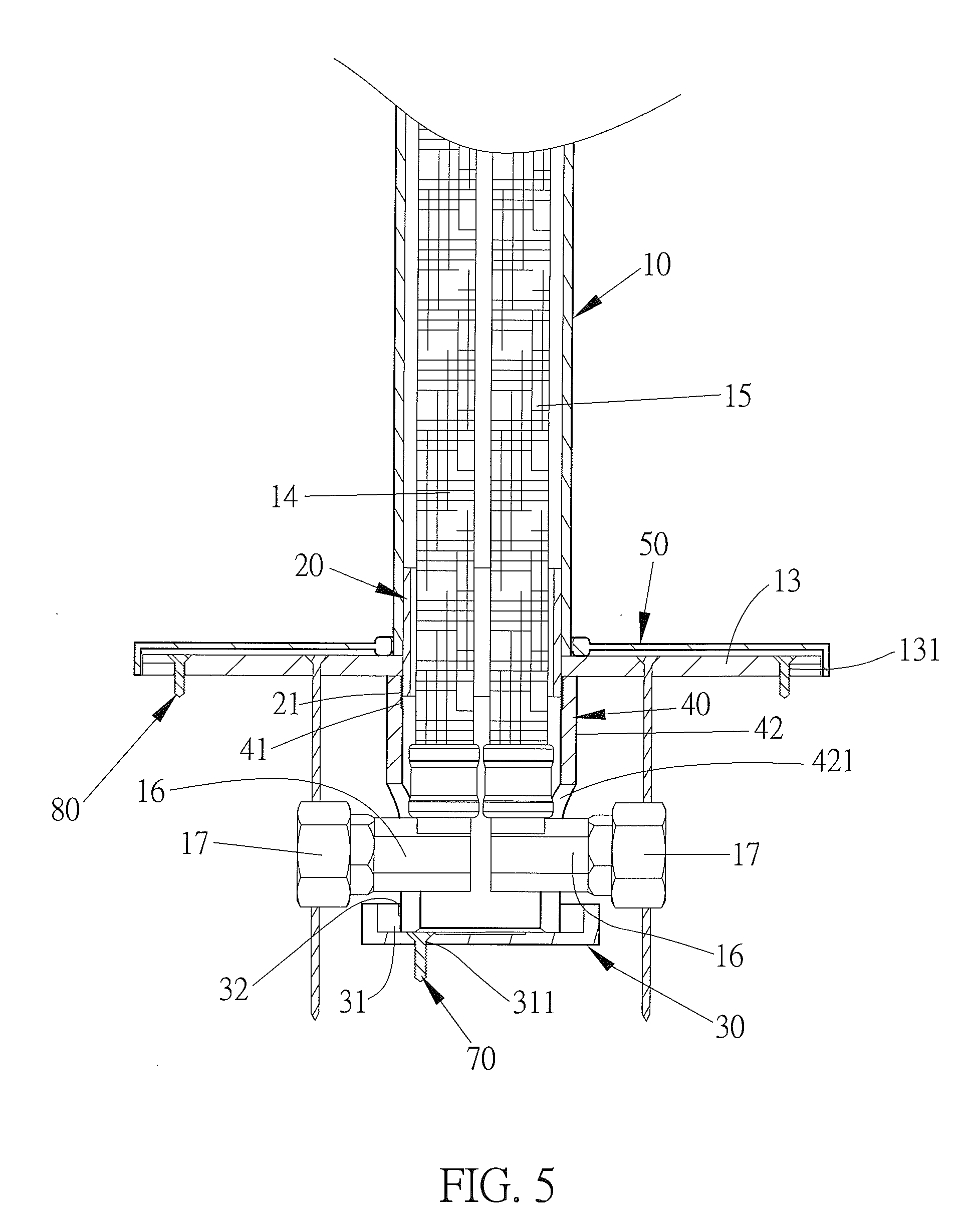
[0017] FIG. 5 is a cross section view showing the assembly of the floor faucet structure according to the preferred embodiment of the present invention.
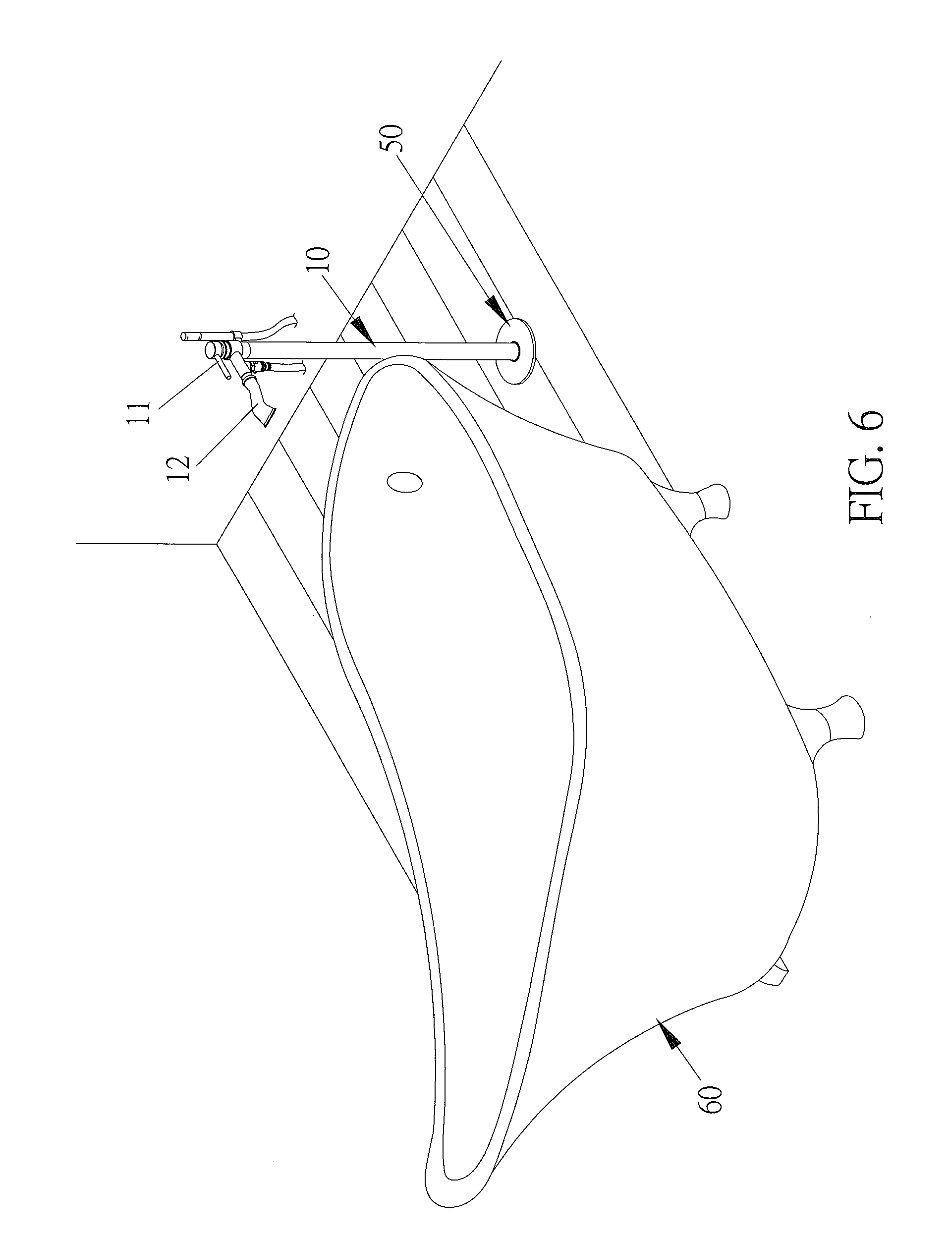
[0018] FIG. 6 is a perspective view showing the application of the floor faucet structure according to the preferred embodiment of the present invention.
[0019] FIG. 7 is a cross sectional view showing the operation of the floor faucet structure according to the preferred embodiment of the present invention.
[0020] FIG. 8 is another cross sectional view showing the operation of the floor faucet structure according to the preferred embodiment of the present invention.
DETAILED DESCRIPTION OF THE PREFERRED EMBODIMENTS
[0021] The present invention will be clearer from the following description when viewed together with the accompanying drawings, which show, for purpose of illustrations only, a preferred embodiment in accordance with the present invention.
[0022] With reference to FIGS. 3-5, a floor faucet structure according to a preferred embodiment of the present invention comprises: a body 10, an adjustable fitting sleeve 20, a fixing seat 30, a connection sleeve 40, and a cap 50.
[0023] The body 10 is an upright pipe and includes a control handle 11 and an outlet tube 12 which are mounted on a top of the body 10, the body 10 also includes a positioning disc 13 disposed on a bottom thereof, and the positioning disc 13 has multiple orifices 131 (in this embodiment, the positioning disc 13 has eight orifices 131). The body 10 further includes a cold-water inlet tube 14 and a hot-water inlet 15 which are accommodated in the body 10, and lower ends of the cold-water inlet tube 14 and the hot-water inlet tube 15 extend out of the body 10 so as to connect with two rotation members 16 respectively, wherein the two rotation members 16 connect with two connectors 17 individually, and the two connectors 17 are perpendicular to the cold-water inlet tube 14 and the hot-water inlet tube 15 separately.
[0024] A cross section of the adjustable fitting sleeve 20 is circular, and the adjustable fitting sleeve 20 is slidably fitted in the bottom of the body 10, the adjustable fitting sleeve 20 includes a first coupling portion 21 formed on a lower end thereof (in this embodiment, the first coupling portion 21 is outer threads) and extending outside an outer wall of the body 10.
[0025] The fixing seat 30 includes a circular groove 31 defined on a top thereof, and the circular groove 31 has multiple through holes 311 formed therein (in this embodiment, three through holes 311 are formed in the circular groove 31). The fixing seat 30 also includes a plurality of retaining ribs 32 arranged on a peripheral wall of the circular groove 31 (in this embodiment, two opposite retaining rib 32 are arranged on the peripheral wall of the circular groove 31).
[0026] The connection sleeve 40 includes a second coupling portion 41 arranged on an upper end thereof (in this embodiment, the second coupling portion 41 is inner threads) so as to connect with the first coupling portion 21 of the body 10, the connection sleeve 40 also includes a cylindrical fence 42 on which two opposite cutouts 421 are formed, such that the two rotation members 16 and the two connectors 17 extend out of the two opposite cutouts 421 respectively. Furthermore, the connection sleeve 40 further includes multiple locking ribs 43 arranged on a lower end thereof (in this embodiment, two opposite locking ribs 43 are arranged on the lower end of the connection sleeve 40).
[0027] The cap 50 is slidably fitted with the outer wall of the body 10.
[0028] In assembly, as shown in FIGS. 6-8, an independent bathtub 60 is fixed on a floor A1 on which an affix aperture A2 is drilled, such that the fixing seat 30 is disposed on a ground B1 below the affix aperture A2 by screwing at least one first screw bolt 70 into the ground B1 via the multiple through holes 311 separately, the second coupling portion 41 of the connection sleeve 40 is connected with the first coupling portion 21 of the adjustable fitting sleeve 20 and is rotated in the circular groove 31 of the fixing seat 30 through the affix aperture A2 of the floor A1, hence the two multiple locking ribs 43 of the connection sleeve 40 retain with the plurality of retaining ribs 32 of the fixing seat 30 respectively so as to fix on the fixing seat 30. In the meantime, the adjustable fitting sleeve 20 is slidably fitted in the bottom of the body 10, and the connection sleeve 40 is adjustably moved relative to the body 10 based on a distance between the floor A1 and the ground B1, hence the body 10 is moved upwardly and downwardly so that the positioning disc 13 matingly contacts with the floor A1. Thereafter, multiple second screw bolts 80 are screwed into the floor A1 via the multiple orifices 131 of the positioning disc 13, and the cap 50 is covered on the positioning disc 13, thus connecting the floor faucet structure.
[0029] Accordingly, the floor faucet structure of the present invention has following advantages:
[0030] 1. The adjustable fitting sleeve 20 is slidably fitted in the bottom of the body 10, and the connection sleeve 40 is adjustably moved relative to the body 10 so as to obtain a desired height correspond to various floors and to fix the floor faucet structure.
[0031] 2. The body 10 includes the cold-water inlet tube 14 and the hot-water inlet 15 which are accommodated in the body 10, and the lower ends of the cold-water inlet tube 14 and the hot-water inlet tube 15 extend out of the body 10 so as to connect with the two rotation members 16 respectively, wherein the two rotation members 16 connect with two connectors 17 individually, and the two connectors 17 are separately perpendicular to the cold-water inlet tube 14 and the hot-water inlet tube 15, the two rotation members 16 and the two connectors 17 extend out of the two opposite cutouts 421 of the connection sleeve 40 respectively. Thus, the cold-water inlet tube 14 and the hot-water tube 15 do not respectively friction and damage the two opposite cutouts 421, when water flows in the cold-water inlet tube 14 and the hot-water tube 15 greatly, thus saving maintenance, replacement, and labor costs, reducing installation time, avoiding deformation of the cold-water tube 14 and the hot-water tube 15, and maintaining water flow.
[0032] While various embodiments in accordance with the present invention have been shown and described, it is clear to those skilled in the art that further embodiments may be made without departing from the scope of the present invention.
* * * * *
D00000
D00001
D00002
D00003
D00004
D00005
D00006
D00007
D00008
XML
uspto.report is an independent third-party trademark research tool that is not affiliated, endorsed, or sponsored by the United States Patent and Trademark Office (USPTO) or any other governmental organization. The information provided by uspto.report is based on publicly available data at the time of writing and is intended for informational purposes only.
While we strive to provide accurate and up-to-date information, we do not guarantee the accuracy, completeness, reliability, or suitability of the information displayed on this site. The use of this site is at your own risk. Any reliance you place on such information is therefore strictly at your own risk.
All official trademark data, including owner information, should be verified by visiting the official USPTO website at www.uspto.gov. This site is not intended to replace professional legal advice and should not be used as a substitute for consulting with a legal professional who is knowledgeable about trademark law.