Damped Abrasive Article
Rifaut; Jean-Luc ; et al.
U.S. patent application number 16/078666 was filed with the patent office on 2019-01-31 for damped abrasive article. The applicant listed for this patent is 3M INNOVATIVE PROPERTIES COMPANY. Invention is credited to Jonathan Charlotteau, Jean-Luc Rifaut.
| Application Number | 20190030683 16/078666 |
| Document ID | / |
| Family ID | 59686524 |
| Filed Date | 2019-01-31 |


| United States Patent Application | 20190030683 |
| Kind Code | A1 |
| Rifaut; Jean-Luc ; et al. | January 31, 2019 |
DAMPED ABRASIVE ARTICLE
Abstract
A damped abrasive article comprises a damping body and an abrasive surface provided on at least a portion of the damping body. The damping body comprises a synthetic polymer having a Storage Modulus from 1000 MPa to 2500 MPa and a Loss factor from 0.025 to 0.10 at 25.degree. C. and 10 Hz.
| Inventors: | Rifaut; Jean-Luc; (Brussels, BE) ; Charlotteau; Jonathan; (Couillet, BE) | ||||||||||
| Applicant: |
|
||||||||||
|---|---|---|---|---|---|---|---|---|---|---|---|
| Family ID: | 59686524 | ||||||||||
| Appl. No.: | 16/078666 | ||||||||||
| Filed: | February 21, 2017 | ||||||||||
| PCT Filed: | February 21, 2017 | ||||||||||
| PCT NO: | PCT/US2017/018623 | ||||||||||
| 371 Date: | August 22, 2018 |
Related U.S. Patent Documents
| Application Number | Filing Date | Patent Number | ||
|---|---|---|---|---|
| 62300476 | Feb 26, 2016 | |||
| Current U.S. Class: | 1/1 |
| Current CPC Class: | B24D 5/16 20130101; B24B 19/009 20130101; B24D 5/06 20130101; B24D 7/18 20130101; B24D 7/066 20130101; B24D 3/001 20130101; B24D 7/16 20130101; B24B 9/08 20130101; B24B 41/007 20130101 |
| International Class: | B24D 7/06 20060101 B24D007/06; B24D 7/18 20060101 B24D007/18 |
Claims
1. A damped abrasive article comprising: a damping body; and an abrasive surface provided on at least a portion of the damping body; wherein the damping body comprises a synthetic polymer having a Storage Modulus from 1000 MPa to 2500 MPa and a Loss factor from 0.025 to 0.10 at 25.degree. C. and 10 Hz.
2. The damped abrasive article of claim 1 wherein the damping body comprises polyamide 6.
3. The damped abrasive article of claim 1 wherein the damping body comprises polyamide 6 and glass fibers.
4. The damped abrasive article of claim 3 wherein the glass fibers comprise from 1 to 50 percent by weight of the damping body.
5. The damped abrasive article of claim 3 wherein the glass fibers comprise 30 percent by weight of the damping body.
6. The damped abrasive article of claim 1 wherein the machine attaching end and the damping body comprise a synthetic polymer having a Storage Modulus from 1000 MPa to 2500 MPa and a Loss factor from 0.025 to 0.10 at 25.degree. C. and 10 Hz.
7. The damped abrasive article of claim 1 wherein the Storage Modulus obtained at 25.degree. C. and 10 Hz is greater than the Storage Modulus obtained at 45.degree. C. and 10 Hz for the damping body.
8. The damped abrasive article of claim 2 wherein the Storage Modulus obtained at 25.degree. C. and 10 Hz is greater than the Storage Modulus obtained at 45.degree. C. and 10 Hz for the damping body.
9. The damped abrasive article of claim 3 wherein the Storage Modulus obtained at 25.degree. C. and 10 Hz is greater than the Storage Modulus obtained at 45.degree. C. and 10 Hz for the damping body.
10. The damped abrasive article of claim 4 wherein the Storage Modulus obtained at 25.degree. C. and 10 Hz is greater than the Storage Modulus obtained at 45.degree. C. and 10 Hz for the damping body.
11. The damped abrasive article of claim 5 wherein the Storage Modulus obtained at 25.degree. C. and 10 Hz is greater than the Storage Modulus obtained at 45.degree. C. and 10 Hz for the damping body.
12. The damped abrasive article of claim 6 wherein the Storage Modulus obtained at 25.degree. C. and 10 Hz is greater than the Storage Modulus obtained at 45.degree. C. and 10 Hz for the damping body.
Description
BACKGROUND
[0001] The present disclosure relates generally to abrasive articles and, more particularly, to abrasive cutters and grinding wheels for brittle materials such as glass, ceramics, glass-ceramics and the like.
[0002] Brittle materials such as glass, ceramic, glass-ceramic are sensitive to chips, cracks, or micro-cracks generated during the machining process. These chips and cracks can reduce the lifetime of the produced part or reduce its mechanical properties such as fatigue strength and flexural strength. Thermal properties are also affected and can lead to rejection of the machined part. The maximum acceptable size of the chips or micro-cracks, which drives their propagation behavior between grain boundaries when exiting or through the solid material, is linked with the structure of the material and the balance of forces applied on the part; it can be calculated using the Griffith law and the Weibull distribution.
[0003] During the machining process of brittle materials like glass, ceramic, glass-ceramic and similar materials, chips and cracks may be generated due to the pressure applied on the machined part when removing material. The chips and micro-cracks are due to the contact force between the working abrasive diamonds and the brittle material. The contact force is needed to penetrate the abrasive diamonds into the material and the relative movement between the diamonds on the tool and the material removes the required material from the workpiece. If there is vibration between the diamonds and the brittle material during the machining process, each diamond acts as a hammer and can generate chips and micro-cracks at the surface of the material or inside it.
[0004] Conventional techniques used to reduce the number and size of chips and micro-cracks include reducing the diamond grit size or grit quality, lowering the bond hardness, or modifying the machine parameters, such as, by reducing the infeed speed. These techniques, however, can negatively affect the productivity of the grinding process by increasing the time needed for the operation and by reducing the useful life of the tool.
[0005] Abrasive articles for glass are known in the prior art. US Patent Publication 2002/0004362 (Lubke) discloses a countersink bit for glass that has a shaft extending along and rotatable about an axis, a head fixed to the shaft and having a frustoconical surface centered on the axis, a layer of grinding material on the surface, and an axially relatively incompressible plastic body capable of transmitting torque between the surface and the shaft. The plastic body has good damping capabilities so that any tendency of the head to vibrate or chatter is largely eliminated.
SUMMARY
[0006] The industry is always seeking improved abrasive articles for brittle materials. More particularly, it would be desirable to provide a grinding wheel for brittle materials, such as glass, ceramics, glass-ceramics and the like, that has improved durability and produces fewer and/or smaller chips, cracks, or micro-cracks in the brittle material during the machining process.
[0007] It has been discovered that improved damping, and thereby a reduction in micro cracks and improved tool life, can be achieved by positioning a damping body formed from a synthetic polymer between a machine attaching end and an abrasive surface in a damped grinding wheel. In particular, the synthetic polymer is selected to have a specific modulus range and loss factor when tested under dynamic cyclic cycling. The range for these properties that achieves the purpose is a Storage Modulus of the damped body of from 1000 MPa to 2500 MPa and a Loss Factor from 0.025 to 0.10 at 25.degree. C. and 10 Hz.
[0008] Thus, in one embodiment the invention resides in a damped abrasive article comprising an abrasive surface comprising abrasive particles and a damping body connected with the abrasive surface; wherein the damping body comprises a synthetic polymer having a Storage Modulus from 1000 MPa to 2500 MPa and a Loss Factor from 0.025 to 0.10 at 25.degree. C. and 10 Hz.
BRIEF DESCRIPTION OF THE DRAWINGS
[0009] FIGS. 1 and 1A illustrate a damped abrasive article according to one embodiment.
[0010] FIGS. 2 and 2A illustrate a damped abrasive article according to another embodiment.
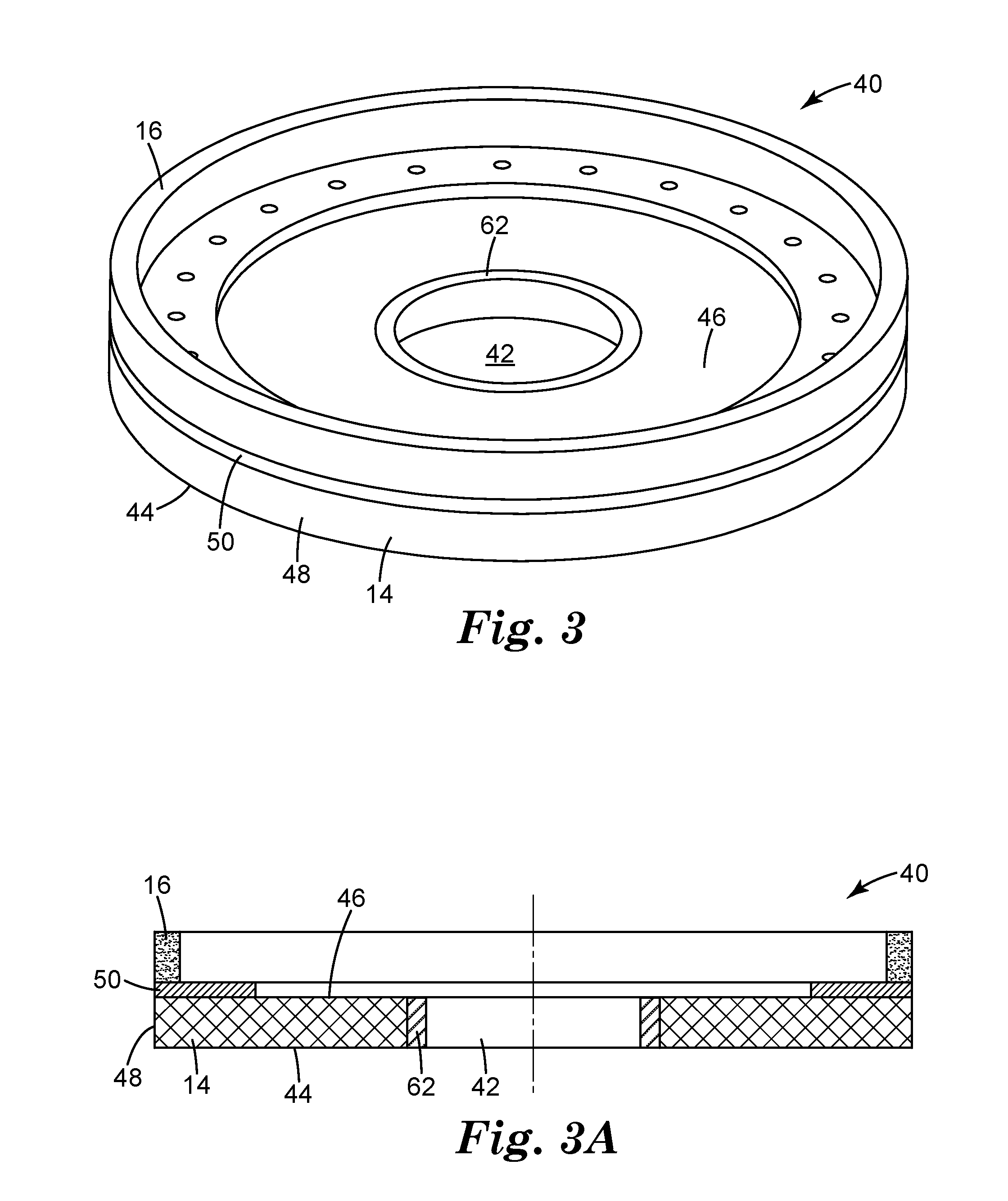
[0011] FIGS. 3 and 3A illustrate a damped abrasive article according to another embodiment.
[0012] FIGS. 4 and 4A illustrate a damped abrasive article according to another embodiment.
[0013] FIGS. 5 and 5A illustrate a damped abrasive article according to another embodiment.
[0014] FIGS. 6 and 6A illustrate a damped abrasive article according to another embodiment.
[0015] FIGS. 7 and 7A illustrate a damped abrasive article according to another embodiment.
[0016] FIGS. 8 and 8A illustrate a damped abrasive article according to another embodiment.
DETAILED DESCRIPTION
[0017] Referring now to FIGS. 1 and 1A, a damped abrasive article 10 in the form of a cutter is shown. More particularly, FIGS. 1 and 1A show an abrasive article 10 in the form of a grinding wheel 40 suited for grinding bio-ceramic prosthesis. The damped abrasive article 10 includes a machine attaching end 12, a damping body 14, and an abrasive cutting surface 16. The machine attaching end 12 is configured to transmit driving torque and linear force from a suitable machine (not shown) to rotate and translate the damped abrasive article 10 relative to a work piece when machining or removing material from the work piece.
[0018] The machine attaching end 12 may comprise a round, square, hexagonal, or polygonal shaft, a tapered shaft and collet, a threaded shaft, a round shaft with flats for the jaws of a chuck, or other suitable mechanical structure to transmit the required torque and linear force. In the illustrated embodiment, the machine attaching end 12 include a first end attachment portion 12a for attachment with the machine, a tapered middle portion 12b, and a cylindrical portion 12c attached with the damping body 14. The first end portion 12a can utilize external or internal threads depending on the configuration of the spindle of the machine used to rotate and translate the damped abrasive article 10. In the illustrated embodiment, the first end portion 12a includes wrench flats 24 or a hole for use with an open-end wrench for installing and removing the first end portion 12a when replacing the damped abrasive article 10.
[0019] Typically the machine attaching end 12 is made from a metal material, such as steel or stainless steel, for use with cooling or cutting fluids during the machining operation. Other suitable metals, such as rigid plastics or the material selected for the damping body 14, can be utilized for the machine attaching end 12.
[0020] In order to cool the damped abrasive article during use, an optional longitudinal bore 26 can be provided through the machine attaching end 12 and through the damping body 14 to supply cooling fluid to the abrasive cutting surface 16. The size of the bore can be selected based on the flow of coolant required.
[0021] Various mechanical interfaces can be used to connect the abrasive cutting surface 16 and the machine attaching end 12 to the damping body 14. For example, the abrasive cutting surface 16 can comprise a hollow cylinder 28 with a recessed bore 30 that mates with the damping body 14 having cylindrical projection 32 extending from a shoulder 34.
[0022] Referring now to FIGS. 2-8, wherein like reference numerals refer to like or corresponding parts throughout the several views, FIGS. 2 and 2A show a grinding wheel 40 suited for fletting tableware glass. The grinding wheel 40 includes an annular damping body 14 and an annular cutting surface 16. The annular damping body 14 contains a central opening 42, opposed first and second major surfaces 44, 46, and an outer circumferential edge surface 48. In the illustrated embodiment, the annular cutting surface 16 includes a beveled edge 16a adjacent the circumferential edge surface 48. The annular abrasive cutting surface 16 is provided on an outer annular region of the damping body 14 second major surface 46 adjacent the outer circumferential edge surface 48 of the damping body. In the illustrated embodiment, the abrasive cutting surface 16 is not provided on an inner annular region of the damping body 16 second major surface 46. It will be recognized, however, that the abrasive cutting surface 16 can be provided on the entirety of the damping body 16 second major surface. In other embodiments, the abrasive cutting surface 16 may be conterminous with the second major surface of the damping body 14, or the cutting surface 16 may be provided in the form of segments or patterns to cover selected regions of the second major surface 46 of the damping body 14. In one embodiment, the abrasive cutting surface 16 is a metal bonded diamond layer glued directly to a polyamide glass fiber reinforced damping body 14. In the illustrated embodiment, the damping body 14 is generally thin and flat and has a uniform thickness. More particularly, the first and second major surface 42, 44 are co-planar.
[0023] FIGS. 3 and 3A show a grinding wheel 40 suited for machining construction glass. The grinding wheel 40 includes an annular damping body 14, an annular cutting surface 16, and an optional annular reinforcing plate 50 arranged between the damping body 14 and the cutting surface 16. The reinforcing plate 50 can be made of metal or filled resin material like filled phenolic resin. The annular damping body 14 contains a central opening 42, and has opposed first and second major surfaces 44, 46 and an outer circumferential edge surface 48. The annular reinforcing plate 50 is provided along an outer annular region of the damping body 14 second major surface 46 adjacent the outer circumferential edge surface 48, and the annular abrasive cutting surface 16 is provided on an outer annular region of the reinforcing plate 50. In the illustrated embodiment, the outer diameters of the damping body 14, the cutting surface 16 and the reinforcing plate 50 are equal and the outer surfaces of the damping body 14, the cutting surface 16 and the reinforcing plate 50 contiguous. In the illustrated embodiment, the grinding wheel 40 further includes an optional annular race or central reinforcing hub 62 provided along the inner annular surface defining the central opening 42. The reinforcing hub 62 enhances the strength of the damping body 14 in the region adjacent the central opening 42 of the grinding wheel 40, and thereby improves the performance and durability of the grinding wheel 40. The reinforcing hub 62 may be secured directly to the damping body 14 by, of example, molding the reinforcing hub 62 and damping body 14 together, or by pressing the reinforcing hub 62 into the damping body 14, or the reinforcing hub 62 may be secured to the damping body 14 by fastening or bonding the reinforcing hub 62 to the damping body 14 using, for example, mechanical fasteners or adhesives.
[0024] In the illustrated embodiment, the inner diameter of the abrasive cutting surface 16 is greater than the inner diameter of the reinforcing plate 50, whereby the radial dimension (i.e. the thickness in the radial dimension) of the cutting surface 16 is less than and the radial dimension of the reinforcing plate, and the cutting surface 16 does not cover an inner annular portion of the reinforcing plate 50. In addition, the inner diameter of the reinforcing plate 50 is greater than the inner diameter of the damping body 14, whereby the radial dimension of the reinforcing plate is less than the radial dimension of the damping body 14 and the reinforcing plate 50 does not cover an inner annular portion of the damping body 14. It will be recognized, however, that the inner and outer diameters of the damping body 14, the cutting surface 16 and the reinforcing plate 50 can be varied depending on the overall construction and intended end-use application for the grinding wheel 40.
[0025] FIGS. 4 and 4A show a grinding wheel 40 similar to the grinding wheel depicted in FIGS. 3 and 3A except the optional reinforcing plate 50 in FIGS. 3 and 3A has been eliminated, the annular damping body 14 includes an annular shoulder portion 14a, the annular abrasive cutting surface 16 is contiguous with the damping body 14 annular shoulder portion 14a, and the annular central reinforcing hub 62 has been enlarged to extend from the central opening 42 to the outer circumferential surface 48.
[0026] FIGS. 5 and 5A show a grinding wheel 40 suited for flute grinding operations on drills or milling tools. The grinding wheel 40 includes an annular damping body 14, an annular cutting surface 16, and an optional annular central reinforcing hub or plate 50. The annular damping body 14 contains a central opening 42, opposed first and second major surfaces 44, 46, and an outer circumferential edge surface 48. In the illustrated embodiment, the outer circumferential edge surface 48 is beveled and flares radially outwardly in the direction from the first major surface 44 to the second major surface 46. The beveled edge surface 48 includes an outer annular recess 52 remote from the central reinforcing hub 62 configured to receive the annular cutting surface 16, whereby the annular abrasive cutting surface 16 is provided along the beveled edge surface 48. The damping body 14 further includes an inner annular recess 54 adjacent the central opening 42 configured to receive the reinforcing hub 62.
[0027] Referring now to FIGS. 6 and 6A, there is shown a grinding wheel 40 suited for machining construction or automotive glass. The grinding wheel 40 includes an annular damping body 14, an annular abrasive cutting surface 16, and an optional annular central hub 62. The annular damping body 14 includes opposed first and second major surfaces 44, 46, an outer circumferential edge surface 48. The annular damping body 14 contains a central opening 42 and a plurality of axial through bores 56. The annular damping body 14 further contains an annular recess or channel 58 adjacent the outer circumferential edge surface 48 adapted to receive the annular abrasive cutting surface 16. The annular damping body 14 includes a pair of shoulder portions 14a that extend along each side of the abrasive cutting surface 16. In the illustrated embodiment, the abrasive cutting surface 16 contains an annular groove 60.
[0028] FIGS. 7 and 7A show a grinding wheel 40 similar to the grinding wheel shown in FIGS. 6 and 6A except one of the shoulder portions 14a has been eliminated and replaced with an annular reinforcing plate 50. The reinforcing plate 50 may formed of an electrically conductive metal material, such as steel, and may be provided with an electrical connection to enable profiling by an electro-erosion process. An electro-erosion process may be used to profile or shape a grinding wheel in which the abrasive incorporated is diamond, cubic boron nitride or similar hard material. The electro-erosion process is able to achieve the required profile precision. As based on fusion, vaporization and ejection of the material due to the energy given by electrical sparking between two electrodes (metal bonded grinding wheel and profiling electrode) placed in a dielectric bath, an electrical conductivity between the abrasive metal bonded layer and the machine is needed.
[0029] Referring now to FIGS. 8 and 8A, there is shown another embodiment of a grinding wheel 40 suited for machining construction or automotive glass. The grinding wheel 40 include an annular damping body 14 and an annular abrasive cutting surface 16. The annular damping body 14 includes opposed first and second major surfaces 44, 46, an outer circumferential edge surface 48. The annular damping body 14 contains a central opening 42 and a plurality of axial bores 56. The annular damping body 14 further contains an annular recess or channel 58 adjacent the outer circumferential edge surface 48 adapted to receive the annular abrasive cutting surface 16. The annular damping body 14 includes a shoulder portion 14a that extends along the second major surface 46 adjacent the abrasive cutting surface 16. In the illustrated embodiment, the abrasive cutting surface 16 contains an annular groove 60. The grinding wheel 40 further includes an annular reinforcing plate 50 arranged along, and contiguous with, the first major surface 44 of the annular damping body 14. As with the embodiment in FIGS. 7 and 7A, the reinforcing plate 50 may formed of an electrically conductive metal material, such as steel, and may be provided with an electrical connection to enable profiling by an electro-erosion process.
[0030] In any of the embodiments described herein, the damping body 14 is made of a synthetic polymer. The polymer can be a thermoplastic, and selected from, for example, polyethylene, polypropylene, polyester, polyamide, polyvinyl, polyetherimide, polydimethylsiloxane or polyetheretherketone for thermoplastic families. For adjusting mechanical, electrical and thermal properties, the synthetic polymer can be reinforced or blended with a filler. Suitable fillers can be fibers or tubes such as carbon fibers or nanotubes, glass fibers, mineral fibers, ceramic fibers, metal fibers or aramid fibers; it can be whiskers such as silicon carbide whiskers or powder such as silicon carbide powder, aluminum oxide powder or metal powder such as aluminum powder, copper powder. Suitable fillers can also include mixtures of those components.
[0031] A quantity of an anti-wearing agent can be added into the mixture in order to reduce the possible wear of the synthetic polymer body during the drilling and/or chamfering operation when abrasive material is machined. Suitable anti-wearing agents include molybdenum disulfide, graphite or PTFE
[0032] In one embodiment, the damping body 14 is made from polyamide 6 reinforced with glass fibers. In one embodiment, glass fibers are used as a reinforcing material at a level from 1 percent to 50 percent, or from 10 percent to 50 percent, or from 30 percent to 50 percent by weight of the polyamide 6 mixture. A 30 percent glass fiber reinforced polyamide 6 mixture is commercially marketed by Ensinger GmbH under the tradename TECAMID 6 GF30 Black. This material was tested for the Storage Modulus and Loss Factor as described below and found to have a Storage Modulus of 1943 MPa and a Loss Factor of 0.033 at 25.degree. C. and 10 Hz.
[0033] Similar mixtures of polyamide 6 with glass fibers are marketed by E.I. du Pont de Nemours--under the tradename DuPont.TM. Zytel.RTM. 73G30T NC010 or DuPont.TM. Zytel.RTM. 73G30T BK261, or by Rhodia SA under the tradename TECHNYL.RTM. C216 V30 BLACK Z/4. Other polyamide 6 producers like EMS-Grivory part of the EMS Group under the trade name Grilon.RTM. B provide suitable products.
[0034] It has been determined that in order to further reduce and/or eliminate chips and micro cracks when using the damped abrasive article 10, the Storage Modulus and the Loss factor of the synthetic polymer is important. These properties can be measured using ASTM D4065 Standard Practice for Plastics: Dynamic Mechanical Properties: Determination and Report of Procedures
[0035] Dynamic mechanical analysis and sample preparation were performed according to the ASTM D4065-12 standard and the procedures mentioned therein. Dynamic mechanical measurements were performed on a DMTA V (Rheometric Scientific) in single cantilever mode in a frequency range from 0.1 to 10 Hz and fixed strain of 0.05% at a temperature of 25.degree. C. to 45.degree. C. Specimens of rectangular shape measuring 20.times.5.times.4 mm are used. The temperature calibration was done using a Fluke 724 Temperature Calibrator, which is regularly calibrated by an accredited calibration institute. PVC standards (available through RHEO Service) were measured on the DMTA periodically to check temperature accuracy. The Storage Modulus and Lost Factor values are obtained at 25.degree. C., 35.degree. C., and 45.degree. C. and at 10 Hz.
TABLE-US-00001 TABLE 1 Storage Modulus and Loss Factor (10 Hz) Storage Loss Loss Modulus Modulus Factor E' E' Tan Material Temp. Mpa Mpa Delta polyamide 6 glass fiber mix 25.degree. C. 1943 64 0.033 (GF30) 35.degree. C. 1575 128 0.081 45.degree. C. 1303 106 0.082 thermoset glass filled phenolic 25.degree. C. 2557 60 0.024 (x680) (Prior Art) 35.degree. C. 3084 69 0.022 45.degree. C. 3059 63 0.021
[0036] As shown in the Examples, a significant reduction in defects during machining of brittle materials and an improved tool life was achieved when the Storage Modulus of the material forming the damped body is from 1000 MPa to 2500 MPa, or from 1000 MPa to 2000 MPa, or from 1200 MPa to 2000 MPa at 25.degree. C. and 10 Hz. Additionally, for the improvements noted above, the Loss Factor of the material forming the damped body is from 0.025 to 0.10, or from 0.03 to 0.10, or from 0.03 to 0.09 at 25.degree. C. and 10 Hz. As listed in Table 1, the Storage Modulus at 45.degree. C. and 10 Hz (1303 Mpa) is lower than the Storage Modulus at 25.degree. C. and 10 Hz (1943 Mpa) for the polyamide 6 glass fiber material used for the damped abrasive article in one embodiment. The prior art thermoset glass filled phenolic had a Storage Modulus that increased as the temperature of the test was increased whereas the Storage Modulus of the polyamide 6 glass fiber mix decreased as the temperature of the test was increased. The Storage Modulus and Loss Factor are determined in accordance with ASTM D4065 and the test parameters described above.
[0037] Another factor in the design of the damped abrasive article is the shape and size of the damped central body 14. In general, the length of the damping body along the longitudinal axis of the abrasive article is preferably from 3 mm to about 60 mm although lengths outside of this range may be used as well. If the length becomes too small insufficient damping may occur, and if the length becomes too great excessive twisting or flexing of the abrasive article may occur during use. In order to reduce such twisting or flexing, a reinforcing plate 50 may be provided on the side of the grinding wheel or in the bore of the grinding wheel.
[0038] In any of the embodiments described herein, the abrasive cutting surface 16 may be provided as, for example, a cutting member affixed to the damping body 14 or as a thin abrasive surface coated onto the damping body 14. In addition, the abrasive cutting surface 16 may be provided as a member, such as an annular member, having a continuous surface, or the abrasive cutting surface 16 may be provided in the form of separate (i.e. individual) segments that define a discontinuous surface. The abrasive cutting member may be affixed to the damping body 14 using mechanical fastening means or bonded to the damping body 14 using, for example, glue or adhesive. In some embodiments, the abrasive cutting surface 16 comprises an abrasive particle in a binder. Any suitable abrasive particle may be included in the abrasive cutting surface. Typically, the abrasive particles have a Mohs' hardness of at least 8, or even 9 and 10. Examples of such abrasive particles include aluminum oxide, fused aluminum oxide, ceramic aluminum oxide, white fused aluminum oxide, heat treated aluminum oxide, silica, silicon carbide, green silicon carbide, alumina zirconia, diamond, iron oxide, ceria, cubic boron nitride, garnet, tripoli, alpha alumina sol-gel derived abrasive particles, and combinations thereof.
[0039] Typically, the abrasive particles have an average particle size of less than or equal to 1500 micrometers, although average particle sizes outside of this range may also be used. For grinding operations, useful abrasive particle sizes typically range from an average particle size in a range of from at least 0.01, 1, 3 or even 5 micrometers up to and including 35, 100, 250, 500, or even as much as 1500 micrometers. In specific embodiments diamond grits between 10 .mu.m and 300 .mu.m are used.
[0040] The abrasive cutting surface is generally made by a molding process. During molding, a binder precursor, either liquid organic, powdered inorganic, powdered organic, or a combination of thereof, could be mixed or not with the abrasive particles. In some instances, a liquid medium (either resin or a solvent) is first applied to the abrasive particles to wet their outer surface, and then the wetted particles are mixed with a powdered medium. The abrasive cutting surface according to the present disclosure may be made by compression molding, injection molding, transfer molding, or the like. The molding can be done either by hot or cold pressing or any suitable manner known to those skilled in the art.
[0041] The binder typically comprises a glassy inorganic material (e.g., as in the case of vitrified abrasive wheels), metal, or an organic resin (e.g., as in the case of resin-bonded abrasive wheels).
[0042] Glassy inorganic binders may be made from a mixture of different metal oxides. Examples of these metal oxide vitreous binders include silica, alumina, calcia, iron oxide, titania, magnesia, sodium oxide, potassium oxide, lithium oxide, manganese oxide, boron oxide, phosphorous oxide, and the like. During manufacture of a vitreous abrasive cutting surface, the vitreous binder, in a powder form, may be mixed with a temporary binder, typically an organic binder. The vitrified binders may also be formed from a frit, for example anywhere from about one to 100 percent frit, but generally 20 to 100 percent frit. Some examples of common materials used in frit binders include feldspar, borax, quartz, soda ash, zinc oxide, whiting, antimony trioxide, titanium dioxide, sodium silicofluoride, flint, cryolite, boric acid, and combinations thereof. These materials are usually mixed together as powders, fired to fuse the mixture and then the fused mixture is cooled. The cooled mixture is crushed and screened to a very fine powder to then be used as a frit binder. The temperature at which these frit bonds are matured is dependent upon its chemistry, but may range from anywhere from about 600.deg. C. to about 1800.deg. C.
[0043] The binder, which holds the shape of the abrasive cutting surface, is typically included in an amount of from 5 to 50 percent, more typically 10 to 25, and even more typically 12 to 24 percent by weight, based on the total weight of the bonded abrasive wheel.
[0044] Examples of metal binders include tin, copper, cobalt, bronze, aluminum, iron, cast iron, manganese, silver, titanium, carbon, chromium, nickel, and combinations thereof in prealloyed forms or not. Metal binders can include fillers such as silicon carbide, aluminum oxide, boron carbide, tungsten, tungsten carbide and combination thereof in prealloyed form or not. During manufacture of a metal abrasive cutting surface, the metal binder, in a powder form, may be mixed with a temporary binder, typically an inorganic binder. The metal binders may also be formed from a mix of pure and prealloyed powder or already pre-mix of metal powders and fillers. These materials are usually mixed together as powders, fired to sinter the mixture and then the sintered mixture is cooled. The temperature at which these metal bonds are matured is dependent upon the chemistry, but may range from anywhere from about 450.degree. C. to about 1100.degree. C.
[0045] The binder, which holds the shape of the abrasive cutting surface, is typically included in an amount of from 65 to 98 percent, more typically 75 to 96, and even more typically 88 to 96 percent by weight, based on the total weight of the bonded abrasive wheel.
[0046] The binder may comprise a cured organic binder resin, filler, and grinding aids. Phenolic resin is the most commonly used organic binder resin, and may be used in both the powder form and liquid state. Although phenolic resins are widely used, it is within the scope of this disclosure to use other organic binder resins including, for example, epoxy resins, polyimide resins, polyamide-imide resins, polyetherimide resins, polyetherketone resins, polyetheretherketone resins, polyethersulfone resins, polyester resins, urea-formaldehyde resins, rubbers, shellacs, and acrylic binders. The organic binder may also be modified with other binders to improve or alter the properties of the binder. The amount of organic binder resin can be, for example, from 15 to 100 percent by weight of the total weight of the binder.
[0047] Useful phenolic resins include novolac and resole phenolic resins. Novolac phenolic resins are characterized by being acid-catalyzed and having a ratio of formaldehyde to phenol of less than one, typically between 0.5:1 and 0.8:1. Resole phenolic resins are characterized by being alkaline catalyzed and having a ratio of formaldehyde to phenol of greater than or equal to one, typically from 1:1 to 3:1. Novolac and resole phenolic resins may be chemically modified (e.g., by reaction with epoxy compounds), or they may be unmodified. Exemplary acidic catalysts suitable for curing phenolic resins include sulfuric, hydrochloric, phosphoric, oxalic, and p-toluenesulfonic acids. Alkaline catalysts suitable for curing phenolic resins include sodium hydroxide, barium hydroxide, potassium hydroxide, calcium hydroxide, organic amines, or sodium carbonate.
[0048] Phenolic resins are well-known and readily available from commercial sources. Examples of commercially available novolac resins include DUREZ 1364, a two-step, powdered phenolic resin (marketed by Durez Corporation of Addison, Tex., under the trade designation VARCUM (e.g., 29302), or HEXION AD5534 RESIN (marketed by Hexion Specialty Chemicals, Inc. of Louisville, Ky.). Examples of commercially available resole phenolic resins useful in practice of the present disclosure include those marketed by Durez Corporation under the trade designation VARCUM (e.g., 29217, 29306, 29318, 29338, 29353); those marketed by Ashland Chemical Co. of Bartow, Fla. under the trade designation AEROFENE (e.g., AEROFENE 295); and those marketed by Kangnam Chemical Company Ltd. of Seoul, South Korea under the trade designation "PHENOLITE" (e.g., PHENOLITE TD-2207).
[0049] In some embodiments, the abrasive cutting surface is affixed to the damping body by an adhesive. Suitable industrial adhesives can be used such as an epoxy product sold under the tradename 3M.TM. Scotch-Weld.TM. Epoxy Adhesive DP460. In other embodiments, the abrasive cutting surface can be fixed to one or more intermediate materials with sufficient strength to transmit the torque from the damping body to the abrasive cutting surface without slipping.
EXAMPLES
Example 1
[0050] A diamond metal bonded abrasive article as shown in FIG. 7 was made to grind the profile of an automotive front windshield in 2.1 mm thick glass. The abrasive article had a damping body made from polyamide 6 reinforced with 30% glass fibers by weight. The polyamide 6 glass fiber mix is commercially marketed by Ensinger GmbH under the tradename TECAMID 6 GF30 Black. This material was tested for the Storage Modulus and Loss Factor as described and found to have a Storage Modulus of 1943 MPa and a Loss Factor of 0.033 at 25.degree. C. and 10 Hz. The abrasive article was operated at xx rpm at a feed rate of xx m/min on a Bystronic machine, dressing every xx pieces and cooled with water slightly emulsified with a lubricant additive. The abrasive article. Lifetime number of ground meters was xx.+GQM
Comparative 1
[0051] A diamond metal bonded abrasive article as shown in FIG. 7 was tested to grind the profile of an automotive front windshield in 2.1 mm thick glass. The abrasive article had a central body made of steel. The abrasive article was operated at 5,100 rpm at a feed rate of 14 m/min, having a material removal of 0.5 mm and dressing every 15 pieces and cooled with water slightly emulsified with a lubricant additive. The abrasive article had a lifetime number of 57112 ground meters including 5 re-profiling. The quality measurement was estimated having a GQM of 30.
* * * * *
D00000
D00001
D00002
D00003
D00004
D00005
D00006
D00007
D00008
XML
uspto.report is an independent third-party trademark research tool that is not affiliated, endorsed, or sponsored by the United States Patent and Trademark Office (USPTO) or any other governmental organization. The information provided by uspto.report is based on publicly available data at the time of writing and is intended for informational purposes only.
While we strive to provide accurate and up-to-date information, we do not guarantee the accuracy, completeness, reliability, or suitability of the information displayed on this site. The use of this site is at your own risk. Any reliance you place on such information is therefore strictly at your own risk.
All official trademark data, including owner information, should be verified by visiting the official USPTO website at www.uspto.gov. This site is not intended to replace professional legal advice and should not be used as a substitute for consulting with a legal professional who is knowledgeable about trademark law.