Interference Patterns for Spiral Wound Elements
Roderick; Kevin ; et al.
U.S. patent application number 16/071567 was filed with the patent office on 2019-01-31 for interference patterns for spiral wound elements. The applicant listed for this patent is Aqua Membranes LLC. Invention is credited to Rodney Herrington, Kevin Roderick, Kendall Weingardt.
| Application Number | 20190030488 16/071567 |
| Document ID | / |
| Family ID | 62145817 |
| Filed Date | 2019-01-31 |


| United States Patent Application | 20190030488 |
| Kind Code | A1 |
| Roderick; Kevin ; et al. | January 31, 2019 |
Interference Patterns for Spiral Wound Elements
Abstract
Embodiments of the present invention provide for the deposition of spacing elements on both opposing surfaces of either an entire folded membrane sheet or portions thereof in combination with features deposited on portions of the same sheet to create spacing geometries not otherwise achievable.
| Inventors: | Roderick; Kevin; (Albuquerque, NM) ; Herrington; Rodney; (Albuquerque, NM) ; Weingardt; Kendall; (Albuquerque, NM) | ||||||||||
| Applicant: |
|
||||||||||
|---|---|---|---|---|---|---|---|---|---|---|---|
| Family ID: | 62145817 | ||||||||||
| Appl. No.: | 16/071567 | ||||||||||
| Filed: | November 17, 2017 | ||||||||||
| PCT Filed: | November 17, 2017 | ||||||||||
| PCT NO: | PCT/US17/62424 | ||||||||||
| 371 Date: | July 20, 2018 |
Related U.S. Patent Documents
| Application Number | Filing Date | Patent Number | ||
|---|---|---|---|---|
| 62424460 | Nov 19, 2016 | |||
| Current U.S. Class: | 1/1 |
| Current CPC Class: | B32B 2255/26 20130101; B32B 2255/24 20130101; B32B 2255/00 20130101; B32B 27/06 20130101; B01D 2313/143 20130101; B01D 63/106 20130101; B32B 3/08 20130101; B32B 9/007 20130101; B32B 37/12 20130101; B32B 7/14 20130101; B32B 9/04 20130101; B32B 1/08 20130101; B01D 2313/08 20130101; B32B 3/30 20130101; B01D 65/08 20130101; B32B 7/12 20130101; B32B 15/04 20130101; B01D 63/103 20130101; B32B 37/18 20130101; B01D 63/10 20130101; B32B 2307/726 20130101; B32B 2597/00 20130101 |
| International Class: | B01D 63/10 20060101 B01D063/10; B01D 65/08 20060101 B01D065/08; B32B 7/12 20060101 B32B007/12; B32B 3/30 20060101 B32B003/30; B32B 37/12 20060101 B32B037/12; B32B 37/18 20060101 B32B037/18 |
Claims
1. A membrane for use in a spiral wound filtration element, comprising a first leaf and a second leaf, where each leaf has an active surface with a plurality of protrusions disposed on the surface, the protrusions being shaped and disposed on the surface such that when the active surface of the first leaf is placed adjacent to the active surface of the second leaf the protrusions are in contact with each other, with the protrusions on the first leaf separated from the active surface of the second leaf by the protrusions on the second leaf; where the first leaf and the second leaf are placed with the active surfaces facing each other and separated by the protrusions.
2. A membrane as in claim 1, comprising a sheet of membrane material, wherein the first leaf comprises a first portion of the sheet; and the second leaf comprises a second portion of the sheet, separated from the first portion by a fold line; and wherein the first and second leafs are placed with active surfaces facing each other by folding the sheet along the fold line.
3. A membrane as in claim 1, wherein the protrusions comprise a plurality of line-shaped protrusions, where the line-shaped protrusions are disposed parallel to each other and separated from each other in all planar directions on the surface of the corresponding leaf; and wherein the line-shaped protrusions are disposed on the surface at an angle other than 90 degrees from the feed edge of the corresponding leaf such that the line-shaped protrusions on the first leaf contact the line-shaped protrusions on the second leaf at their intersections.
4. A membrane as in claim 3, wherein the angle is between 40 and 85 degrees, or between 100 and 135 degrees.
5. A membrane as in claim 1, wherein the protrusions protrude from the surface of each leaf by at least 0.065 mm but not more than 0.4 mm.
6. A membrane as in claim 1, wherein the protrusions comprise a plurality of curved features, configured such that the curved feature on the first leaf will intersect the curved features on the second leaf at an angle other than 0 degrees when the membrane is spirally wound.
7. A membrane as in claim 3, wherein the line-shaped protrusions extend across the entire width of the corresponding leaf.
8. A membrane as in claim 3, wherein the line-shaped protrusions extend across less than the entire width of the corresponding leaf.
9. A membrane as in claim 8 wherein the line-shaped protrusions are at least length 20 mm long in the axial dimension and the spacing between line segments is less than the length of the line segments.
10. A membrane as in claim 1, wherein the protrusions are disposed in a first region of the first leaf, and in a first region of the second leaf, and further comprising a plurality of flow protrusions disposed (a) on the active surface of the first leaf other than in the first region of the first leaf, (b) on the active surface of the second leaf other than in the first region of the second leaf, or (c) both, wherein the flow protrusions have a height about equal to the sum of the height of the protrusions in the first region of the first leaf and the height of the protrusions in the first region of the second leaf, and wherein flow protrusions on one leaf do not contact those on the other leaf when the element is spiral wound.
11. A membrane as in claim 10, wherein the flow protrusions are disposed on the first leaf and not on the second leaf.
12. A membrane as in claim 8, wherein the line-shaped protrusions are disposed in regions proximal the feed and reject edges of the corresponding leaf, and further comprising a plurality of flow protrusions disposed (a) on the active surface of the first leaf in regions other than those occupied by the line-shaped protrusions, (b) on the active surface of the second leaf in regions other than those occupied by the line-shaped protrusions, or (c) both, wherein the flow protrusions have a height about equal to the sum of the height of the line-shaped protrusions on the first leaf and the height of the line-shaped protrusions on the second leaf; and wherein the flow protrusions on one leaf do not contact those on the other leaf when the element is spiral wound.
13. A membrane as in claim 12, wherein the flow protrusions are disposed on the first leaf and not on the second leaf.
14. A method of making a membrane, comprising providing a first leaf and a second leaf, each having an active surface; placing a plurality of protrusions on the active surface of each leaf, the protrusions being shaped and disposed on the surface such that when the active surface of the first leaf is placed adjacent to the active surface of the second leaf the protrusions are in contact with each other with the protrusions on the first leaf separated from the active surface of the second leaf by the protrusions on the second leaf; placing the active surface of the first leaf adjacent to the active surface of the second leaf, separated by the protrusions.
15. A method as in claim 14, wherein providing a first leaf and a second leaf comprises providing a sheet separated into a first leaf and a second leaf by a fold line; and wherein placing the active surface of the first leaf adjacent to the active surface of the second leaf comprises folding the sheet along the fold line.
16. A filtration element comprising a membrane as in claim 1, spirally wound around a center tube.
17. A fluid treatment system, comprising a plurality of filtration elements as in claim 16.
18. A method of treating a fluid, comprising flowing the fluid through a filtration element as in claim 16.
19. A membrane for use in a spiral wound filtration element, comprising a sheet having an active surface, the sheet folded with the active surface inside the folded sheet, wherein the active surface has a plurality of protrusions disposed thereon, the protrusions being shaped and disposed on the surface such that the protrusions contact each other and hold apart the facing active surfaces in the folded sheet.
20. A membrane as in claim 19, wherein the protrusions comprise a plurality of line-shaped protrusions disposed on the active surface at an angle other than 90 degrees to the feed edge of the membrane.
21. A membrane as in claim 20, wherein the angle is between 40 and 85 degrees, or between 100 and 135 degrees.
22. A membrane as in claim 20, wherein the protrusions protrude from the surface of each leaf by at least 0.065 mm but not more than 0.4 mm.
Description
TECHNICAL FIELD
[0001] The subject invention relates to a permeable membrane system useful for the separation of fluid components, including spiral-wound membrane permeable membrane elements.
BACKGROUND ART
[0002] Spiral-wound membrane filtration elements consist of a laminated structure comprised of a membrane sheet sealed to or around a porous permeate spacer which creates a path for removal of the fluid passing through the membrane to a central tube, while this laminated structure is wrapped spirally around the central tube and spaced from itself with a porous feed spacer to allow axial flow of the fluid through the element. While this feed spacer is necessary to maintain open and uniform axial flow between the laminated structure, it is also a source of flow restriction and pressure drop within the axial flow channel and also presents areas of restriction of flow and contact to the membrane that contribute significantly to membrane fouling via biological growth, scale formation, and particle capture.
[0003] Improvements to the design of spiral wound elements have been disclosed by Barger et al and Bradford et al., which replace the feed spacer with islands or protrusions either deposited or embossed directly onto the outside or active surface of the membrane. This configuration is advantageous in that it maintains spacing for axial flow through the element while minimizing obstruction within the flow channel. It also eliminates the porous feed spacer as a separate component, thus simplifying element manufacture. Patent publication number US2016-0008763-A1 entitled Improved Spiral Wound Element Construction teaches the application of printed patterns on the back side of the active surface of the membrane sheet, or directly on the surface of the permeate spacer.
[0004] The following references, each of which is incorporated herein by reference, can facilitate understanding of the invention: U.S. Pat. No. 3,962,096; U.S. Pat. No. 4,476,022; U.S. Pat. No. 4,756,835; U.S. Pat. No. 4,834,881; U.S. Pat. No. 4,855,058; U.S. Pat. No. 4,902,417; U.S. Pat. No. 4,861,487; U.S. Pat. No. 6,632,357; and US application 2016-0008763-A1.
SUMMARY OF INVENTION
[0005] Embodiments of the present invention provide a membrane for use in a spiral wound filtration element, comprising a first leaf and a second leaf, where each leaf has an active surface with a plurality of protrusions disposed on the surface, the protrusions being shaped and disposed on the surface such that when the active surface of the first leaf is placed adjacent to the active surface of the second leaf the protrusions are in contact with each other, with the protrusions on the first leaf separated from the active surface of the second leaf by the protrusions on the second leaf; where the first leaf and the second leaf are placed with the active surfaces facing each other and separated by the protrusions. The two leafs can be separate sheets of a suitable material, or can be provided by folding a single sheet, with each side of the fold providing one leaf. Note that a membrane for use in a spiral wound filtration element inherently has two edges, the feed edge and reject edge, corresponding to the edges of the membrane that will encounter feed fluid flow and eject waste fluid flow respectively. Such a membrane also inherently has a width, corresponding to the dimension of the material between the feed and reject edges.
[0006] In some embodiments, the protrusions comprise a plurality of line-shaped protrusions, where the line-shaped protrusions are disposed parallel to each other and separated from each other in all planar directions on the surface of the corresponding leaf; and wherein the line-shaped protrusions are disposed on the surface at an angle other than 90 degrees from the feed edge of the corresponding leaf such that the line-shaped protrusions on the first leaf contact the line-shaped protrusions on the second leaf at their intersections. The line-shaped protrusions can extend across the entire width of the leaf, or can extend across less than the entire width. In some embodiments, the angle is between 40 and 85 degrees, or between 100 and 135 degrees. In some embodiments, the protrusions protrude from the surface of each leaf by at least 0.065 mm but not more than 0.4 mm. In some embodiments, the protrusions comprise a plurality of curved features, configured such that the curved feature on the first leaf will intersect the curved features on the second leaf at an angle other than 0 degrees when the membrane is spirally wound. In some embodiments, the line-shaped protrusions are at least 20 mm long in the axial dimension (the component of the length measured parallel to the axis of the center tube when spirally wound) and the spacing between line segments is less than the length of the line segments.
[0007] In some embodiments, the protrusions are disposed in a first region of the first leaf, and in a first region of the second leaf, the embodiment further comprises a plurality of flow protrusions disposed (a) on the active surface of the first leaf other than in the first region of the first leaf, (b) on the active surface of the second leaf other than in the first region of the second leaf, or (c) both, wherein the flow protrusions have a height about equal to the sum of the height of the protrusions in the first region of the first leaf and the height of the protrusions in the first region of the second leaf, and wherein flow protrusions on one leaf do not contact those on the other leaf when the element is spiral wound.
[0008] In some embodiments, the line-shaped protrusions are disposed in regions proximal the feed and reject edges of the corresponding leaf, and the embodiment further comprises a plurality of flow protrusions disposed (a) on the active surface of the first leaf in regions other than those occupied by the line-shaped protrusions, (b) on the active surface of the second leaf in regions other than those occupied by the line-shaped protrusions, or (c) both, wherein the flow protrusions have a height about equal to the sum of the height of the line-shaped protrusions on the first leaf and the height of the line-shaped protrusions on the second leaf; and wherein the flow protrusions on one leaf do not contact those on the other leaf when the element is spiral wound.
[0009] The present invention also provides a method of making a membrane, comprising providing a first leaf and a second leaf, each having an active surface; placing a plurality of protrusions on the active surface of each leaf, the protrusions being shaped and disposed on the surface such that when the active surface of the first leaf is placed adjacent to the active surface of the second leaf the protrusions are in contact with each other with the protrusions on the first leaf separated from the active surface of the second leaf by the protrusions on the second leaf; placing the active surface of the first leaf adjacent to the active surface of the second leaf, separated by the protrusions. Providing a first leaf and a second leaf can comprise providing two separate sheets, or can comprise providing a sheet separated into a first leaf and a second leaf by a fold line.
[0010] The present invention also provides a filtration element as those described herein, spirally wound around a center tube. The present invention also provides a fluid treatment system, comprising a plurality of filtration elements as those described herein. The present invention also provides a method of treating a fluid, comprising flowing the fluid through a filtration element as those described herein.
[0011] Some embodiments provide a membrane for use in a spiral wound filtration element, comprising a sheet having an active surface, the sheet folded with the active surface inside the folded sheet, wherein the active surface has a plurality of protrusions disposed thereon, the protrusions being shaped and disposed on the surface such that the protrusions contact each other and hold apart the facing active surfaces in the folded sheet. In some embodiments, the protrusions comprise a plurality of line-shaped protrusions disposed on the active surface at an angle other than 90 degrees to the feed edge of the membrane. In some embodiments, the angle is between 40 and 85 degrees, or between 100 and 135 degrees. In some embodiments, the protrusions protrude from the surface of the sheet by at least 0.065 mm but not more than 0.4 mm.
BRIEF DESCRIPTION OF THE DRAWINGS
[0012] FIG. 1 is an illustration of opposing patterns of solid lines on opposing faces of a single folded membrane leaf.
[0013] FIG. 2 is an illustration of opposing patterns of segmented lines on opposing faces of a single folded membrane leaf.
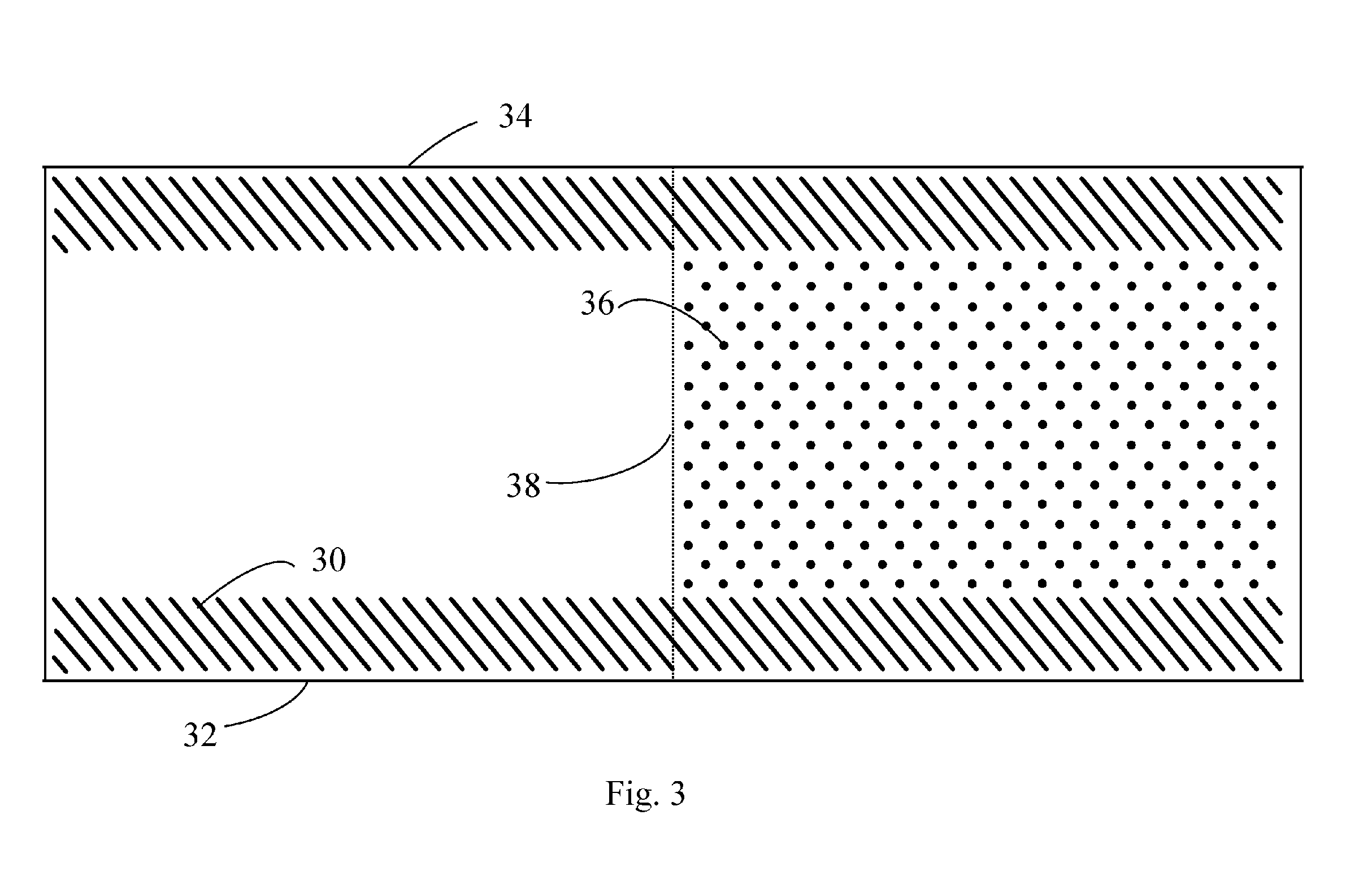
[0014] FIG. 3 is an illustration of a membrane leaf with half-height edge patterns deposited along the full length of the inlet and outlet edges of the leaf and full height features deposited on one half of the membrane leaf.
[0015] FIG. 4 is a representation of membrane feed spacers that have curved lead in features on the feed end of the membrane element and that are trimmed after rolling the element.
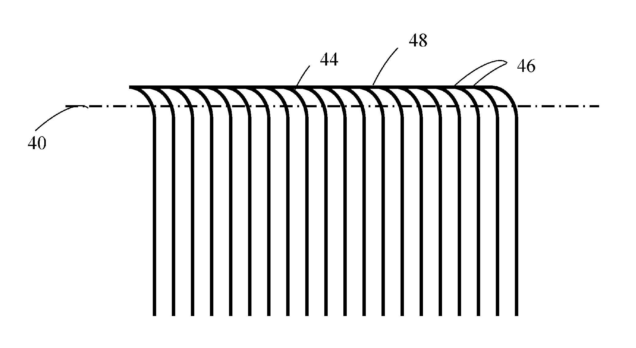
[0016] FIG. 5 is a representation of membrane feed spacers that have curved lead in features on the feed end of the membrane element and curved anti-telescoping device features to help avoid end blocking of the element from high solids fluids.
DESCRIPTION OF EMBODIMENTS AND INDUSTRIAL APPLICABILITY
[0017] Embossing or depositing features onto the surface of the membrane sheet, or onto or into the permeate carrier sheet of a spiral-wound element to provide spacing between adjacent membrane sheets can provide several advantages as compared to feed spacer mesh including more open flow channels, lower pressure drop, reduced fouling, and the ability to produce thinner feed space than is practical using a mesh. Various configurations have been disclosed by Barger et al, Bradford et al, and in PCT/US2014/018813. Embodiments of the present invention provide the use of printed or otherwise deposited surface features that selectively contact one another to provide spacing between adjacent membrane sheets to create unique contact and flow patterns not achievable by deposition of isolated islands. The patterns created thereby may also contain other deposited features that do not contact one another to provide additional spacing and flow direction within the spiral-wound element. Additionally, variable heights of printed or otherwise deposited features can be employed to produce different spacer geometries on different areas of the spiral-wound element.
[0018] Previous disclosures of printing, embossing, or otherwise depositing features to provide feed spacing in spiral-wound elements typically involve deposition of the features on one half of each folded membrane leaf to provide the spacing while eliminating the possibility of having the features contact one another or stack when the leaf is folded. Contact and geometry considerations are made more complex when a spiral-wound element is rolled because of the changing radii of the leaf sections to one another and to the rest of the components of the element. In some cases, however, having spacing elements deposited across all or part of the membrane surface which are designed to contact one another upon folding can be beneficial. Deposition patterns or features can be configured such that when the sheet is folded and rolled, there is no possibility at any point for the patterns to nest within the opposing pattern and feature-to-feature contact is ensured rather than feature-to-membrane contact.
[0019] In an example embodiment shown in FIG. 1, a series of continuous angled parallel lines 10 are deposited on the membrane surface extending from the edge corresponding to the inlet flow of the rolled element to the edge corresponding to the outlet flow. In this example, the printed lines can be between 0.065 mm and 0.80 mm wide and from 0.065 mm to 0.40 mm tall. Spacing between adjacent elements should be close enough to prevent collapse of the membrane sheet between the parallel lines during membrane rolling due to the viscosity of the adhesive used to form the envelope between the membrane sheet, the adjacent permeate carrier and the next membrane sheet. For materials in common use today, this spacing can be no more than 3 mm from one line to the next, and more preferably is 2.5 mm. Any angle between 0.degree. and 90.degree. or between 90.degree. and 180.degree. from the inlet flow edge 14 can be used to ensure feature to feature contact on the folded leaf, but angles in the ranges from 45-80.degree. or 100-135.degree. can be more suitable to maintain acceptable flow and pressure drop through the element. When folded, the deposited patterns 10 will contact the opposite pattern 12 at a supplementary angle such that the deposited patterns will repeatedly cross and support each other without letting the pattern from the opposite side contact the membrane film directly. The lines can be straight lines as shown, and can also be curved, sinusoidal, or otherwise shaped provided they contain no extended segments (e.g. <10 mm) where the pattern is near 90.degree.. Patterns that are not straight lines can be chosen for particular performance characteristics, e.g., to improve mixing or to lengthen or shorten the flow path across the membrane surface.
[0020] In another example embodiment shown in FIG. 2, line segments 20 can be used instead of continuous lines to produce the pattern that will contact itself 22 when folded. In this example, the printed pattern can be between 0.065 mm and 0.80 mm wide and from 0.065 mm to 0.40 mm tall. Spacing between adjacent elements should be close enough to prevent collapse of the membrane sheet between the parallel lines during membrane rolling due to the viscosity of the adhesive used to form the envelope between the membrane sheet, the adjacent permeate carrier and the next membrane sheet. With materials in common use today, this spacing can be no more than 3 mm from one line to the next, and more preferably is 2.5 mm. Any angle between 0.degree. and 90.degree. or between 90.degree. and 180.degree. from the inlet flow edge 24 can be used to ensure feature to feature contact on the folded leaf, but angles in the ranges from 45-80.degree. or 100-135.degree. can be more suitable to maintain acceptable flow and pressure drop through the element. Rolling of a spiral-wound element, even when done in an automated fashion, is still inexact. Typically folded leaves within a given element are able to move as much as +/-10 mm axially to the center tube of the element due to movement of the various sheet materials and glue used in assembly. As such, minimum feature length of beyond 20 mm in the axial dimension will generally be needed to ensure contact between adjacent features in folded leaves. Gaps between adjacent line segments in the axial dimension are shorter than the feature length in the axial dimension to avoid any possibility of nesting of features when folded. In this embodiment the line segments can also be straight, curved, sinusoidal, or otherwise repetitively varying.
[0021] Maintaining open spacing at the inlet and outlet edges of the element while minimizing flow restriction within the flow channel can also be enhanced by combining full leaf length deposition where features meet to support each other when folded with areas of feature deposition that are not designed to interfere with adjacent features after folding. This allows the patterns that are not designed to interfere with adjacent features after folding to comprise a variety of shapes that are not limited to lines or line segments, such as circular or polygonal posts, curved line segments or other shapes that alter flow in a desirable manner. In an example shown in FIG. 3, the printed interference pattern 30 along the inlet 32 and outlet 34 edges can be between 0.065 mm and 0.80 mm wide and from 0.065 mm to 0.40 mm tall, and extend from 40 mm to 80 mm axially from the inlet and outlet edge of the membrane leaf. Any angle between 0.degree. and 90.degree. or between 90.degree. and 180.degree. from the inlet and outlet flow edge can be used to ensure feature to feature contact on the folded leaf, but angles in the ranges from 45-80.degree. or 100-135.degree. can be more suitable to maintain acceptable flow and pressure drop through the element. Another pattern is deposited in the center section 30 on half of the membrane leaf and can be twice as tall as the features on the edges so that, when the leaf is folded along its center line 38, the spacing on the edges and the central area is uniform. In general the patterns deposited at the edge are spaced more densely to support the glue line used to bond the leaves together while the central pattern are spaced more sparsely to allow less restricted flow through this portion of the element.
[0022] In a specific example embodiment a pattern of solid line segments 30, 0.6 mm wide and 93 mm long, is deposited extending from the inlet 32 and outlet 34 edge, at an angle of 45.degree. relative to the edge of the membrane sheet such that it extends 66 mm inward onto the leaf at a height that is one half the desired finished feed space height, in this case 0.2 mm for a 0.4 mm total feed spacing after folding. Another pattern, a square array of circular posts 36, 1.2 mm in diameter spaced 6.5 mm from one another, is then deposited on the central area between the two 0.2 mm patterns to a height of 0.4 mm. This pattern is only deposited along one-half the length of the overall leaf such that when the leaf is folded in half at the center line 38, the edge patterns contact one another to create 0.4 mm feed space at the edges while the central pattern creates the 0.4 mm spacing in the middle of the leaf.
[0023] In another embodiment of the present invention shown in FIG. 4, curved inlet brine feed spacer features can be utilized. These features can be printed or deposited on one half of the membrane leaf along the inlet and outlet edges and only extend far enough to provide support to the area of the glue line. During rolling and gluing the element, the curved features 44 at the inlet and outlet edge create a tighter pattern where the tips 46 approach one another such that during rolling the patterns provide support to the adjacent layer as the spiral wound element is rolled. In another embodiment of the present invention shown in FIG. 5, the space between tips 46 can be reduced to zero thereby making a continuous solid line 48 that provides more complete support of the glue line during rolling operations. After the ends of the element are trimmed at trim line 40, the tighter spacing of the curved portions is removed which opens up the inlet and outlet spacing between the features to facilitate fluid flow and help avoid pressure losses at the ends of the element. In conventional spiral wound membranes, the flow of fluid into the brine feed spaces is normal (flow vector is parallel to the axis of the center tube) to the end of the element, and materials in the fluid stream can stack up at the end of the brine feed channels and thereby block the fluid feed channels. This fluid blockage at the feed end of the element can be mitigated by creating a fluid flow stream that is partially diverted in a flow vector that is at an angle from the centerline of the element. By creating a sweeping motion of fluid as it enters the brine feed spaces, materials that might have accumulated at the feed spaces can be swept away. In FIG. 6, turning vanes 60 have curved surfaces that impart a lateral flow at the end of the rolled element to help avoid end blocking of the element by sweeping solids in the fluid stream from the end face of the spiral wound element that can be entering the brine feed space channels of the spiral wound element. The view of FIG. 6 is shown as a flat, un-rolled view of a spiral wound element. Normally, this pattern is wrapped around a center tube, but is shown in FIG. 6 to more easily describe the concept. Brine feed solution 66 is normal (parallel to the axis of the center tube) as it enters the end of the spiral wound element. Turning vanes 60 impart a flow pattern that is across the end of the spiral wound element thereby keeping material from accumulating on the end of the brine feed channel. As the printed spacers 64 enter the element, there is a curved inlet component 62 that maintains the brine feed solution 66 in line with the flow vector of brine feed solution 66. As brine feed solution enters the membrane feed space, printed spacers 64 help align the flow vector of brine feed solution 66 to be more parallel to the center line of the membrane element center tube. However, it will be known to those familiar with the prior art that these printed spacers 64 can have various shapes and configurations to stimulate localized vorticity and reduce concentration polarization in the brine feed spaces of the spiral wound element.
[0024] The features can be deposited by a variety of techniques. Traditional printing techniques such as offset printing, gravure printing, and screen printing, can be suitable, although there might be thickness and geometry limitations with these deposition techniques. Thicker features can be deposited by microdispensing, inkjet printing, fused deposition, photo polymer technology, hot melt polymers, or via application using an adhesive that can include roll transfer of sheet or pick-and-place of individual features.
[0025] The features can be comprised of any number of materials which are compatible with the separated fluid and the permeate carrier including, but not limited to, thermoplastics, reactive polymers, waxes, or resins. Additionally, materials that are compatible with the separated fluid but not compatible with direct deposition to the membrane sheet, including, but not limited to high-temperature thermoplastics, metals, or ceramics, can be pre-formed, cast, or cut to the proper dimensions and adhered to the surface of the membrane sheet with an adhesive that is compatible with the membrane sheet.
[0026] The present invention has been described in connection with various example embodiments. It will be understood that the above description is merely illustrative of the applications of the principles of the present invention, the scope of which is to be determined by the claims viewed in light of the specification. Other variants and modifications of the invention will be apparent to those skilled in the art.
* * * * *
D00000
D00001
D00002
D00003
D00004
D00005
D00006
XML
uspto.report is an independent third-party trademark research tool that is not affiliated, endorsed, or sponsored by the United States Patent and Trademark Office (USPTO) or any other governmental organization. The information provided by uspto.report is based on publicly available data at the time of writing and is intended for informational purposes only.
While we strive to provide accurate and up-to-date information, we do not guarantee the accuracy, completeness, reliability, or suitability of the information displayed on this site. The use of this site is at your own risk. Any reliance you place on such information is therefore strictly at your own risk.
All official trademark data, including owner information, should be verified by visiting the official USPTO website at www.uspto.gov. This site is not intended to replace professional legal advice and should not be used as a substitute for consulting with a legal professional who is knowledgeable about trademark law.