Humidity Controller
Hunt; Peter John ; et al.
U.S. patent application number 16/011535 was filed with the patent office on 2019-01-31 for humidity controller. The applicant listed for this patent is FISHER & PAYKEL HEALTHCARE LIMITED. Invention is credited to Peter John Hunt, Stephen William McPhee, Mohammad Thudor, David Fraser Wixey.
| Application Number | 20190030276 16/011535 |
| Document ID | / |
| Family ID | 65236500 |
| Filed Date | 2019-01-31 |


| United States Patent Application | 20190030276 |
| Kind Code | A1 |
| Hunt; Peter John ; et al. | January 31, 2019 |
HUMIDITY CONTROLLER
Abstract
A breathing assistance apparatus adapted to deliver humidified gases at a desired level of humidity to a patient including a humidifier and a heated conduit is disclosed. The humidifier includes a controller which determines the flow rate of the gases and then determines the required power input to the humidifier to deliver the gases to the patient at the required patient humidity. This means the need for external sensors is dispensed with and thus the apparatus is simple and less bulky.
| Inventors: | Hunt; Peter John; (Auckland, NZ) ; Thudor; Mohammad; (Auckland, NZ) ; Wixey; David Fraser; (Auckland, NZ) ; McPhee; Stephen William; (Auckland, NZ) | ||||||||||
| Applicant: |
|
||||||||||
|---|---|---|---|---|---|---|---|---|---|---|---|
| Family ID: | 65236500 | ||||||||||
| Appl. No.: | 16/011535 | ||||||||||
| Filed: | June 18, 2018 |
Related U.S. Patent Documents
| Application Number | Filing Date | Patent Number | ||
|---|---|---|---|---|
| 14942040 | Nov 16, 2015 | 10130787 | ||
| 16011535 | ||||
| 13159345 | Jun 13, 2011 | 9186477 | ||
| 14942040 | ||||
| 12274020 | Nov 19, 2008 | 7962018 | ||
| 13159345 | ||||
| 10715324 | Nov 17, 2003 | |||
| 12274020 | ||||
| 10001596 | Oct 19, 2001 | 7106955 | ||
| 10715324 | ||||
| 09959226 | Jan 23, 2002 | |||
| 10001596 | ||||
| 09959226 | Jan 23, 2002 | |||
| PCT/NZ2000/000156 | Aug 9, 2000 | |||
| 10001596 | ||||
| Current U.S. Class: | 1/1 |
| Current CPC Class: | A61M 2205/3368 20130101; A61M 16/1075 20130101; A61M 2016/0039 20130101; A61M 2205/50 20130101; A61M 16/1085 20140204; A61M 16/1095 20140204; G05D 22/02 20130101; A61M 16/162 20130101; G01F 1/684 20130101; A61M 2205/18 20130101; G01F 1/6888 20130101; A61M 16/0066 20130101; A61M 2205/33 20130101; A61M 16/0051 20130101; A61M 2205/3331 20130101; A61M 2205/3653 20130101; A61M 16/024 20170801; A61M 16/0875 20130101; A61M 16/16 20130101; G01F 1/6842 20130101; A61M 16/109 20140204; A61M 16/161 20140204 |
| International Class: | A61M 16/16 20060101 A61M016/16; G05D 22/02 20060101 G05D022/02; A61M 16/10 20060101 A61M016/10; G01F 1/684 20060101 G01F001/684; G01F 1/688 20060101 G01F001/688; A61M 16/08 20060101 A61M016/08 |
Foreign Application Data
| Date | Code | Application Number |
|---|---|---|
| Aug 23, 1999 | NZ | 337382 |
| Oct 19, 2000 | NZ | 507663 |
Claims
1-32. (canceled)
33. A breathing assistance apparatus comprising: a heater configured to heat water to humidify gases, the heater further configured to be in a fluid communication with a conduit configured to deliver the gases to a patient; and a controller configured to: cause an initial power level to be supplied to the heater to maintain a heater temperature at an initial temperature level; determine a flow rate of the gases based on an output of a flow sensor; based on the flow rate of the gases, determine a power level to heat the gases to a selected temperature or humidify the gases to a selected humidity and cause the determined power level to be supplied to the heater; monitor a change in the flow rate of the gasses; in response to determining that the change in the flow rate of the gases satisfies a first threshold but does not satisfy a second threshold, redetermine the power level to heat the gases to the selected temperature or to humidify the gases to the selected humidity and cause the redetermined power level to be supplied to the heater; and in response to determining that the change in the flow rate satisfies the second threshold, cause the initial power level to be supplied to the heater, the second threshold being indicative of a larger change in the flow rate of the gases than the first threshold.
34. The apparatus of claim 33, wherein the controller is further configured to: in response to determining that 1) the change in the flow rate of the gases satisfies the first threshold but does not satisfy the second threshold and 2) the change in the flow rate of the gases indicates an increase in the flow rate of the gases, delay redetermination of the power level to heat the gases to the selected temperature or to humidify the gases to the selected humidity for a first period of time.
35. The apparatus of claim 34, wherein the controller is further configured to: in response to determining that 1) the change in the flow rate of the gases satisfies the first threshold but does not satisfy the second threshold and 2) the change in the flow rate of the gases indicates a decrease in the flow rate of gases, delay redetermination of the power level to heat the gases to the selected temperature or to humidify the gases to the selected humidity for a second period of time shorter than the first period of time.
36. The apparatus of claim 33, further comprising a temperature sensor configured to measure the heater temperature, wherein the controller is further configured to: determine an expected heater temperature based on the flow rate of the gasses; and in response to determining that the expected heater temperature deviates from the measured heater temperature by a threshold temperature, redetermine the power level to heat the gases to the selected temperature or to humidify the gases to the selected humidity and cause the redetermined power level to be supplied to the heater.
37. The apparatus of claim 33, wherein the flow rate of the gases depends at least in part on one or more restrictions in a flow path configured to accommodate a flow of the gases.
38. The apparatus of claim 33, wherein the controller is further configured to determine a conduit heater power level to heat the gases flowing through the conduit and cause the conduit heater power level to be supplied to the conduit heater.
39. The apparatus of claim 38, wherein the controller is further configured to increase the conduit heater power level in response to at least one of: increase in the flow rate of the gases, decrease in ambient temperature, or increase in a difference between the ambient temperature and a temperature of the gases.
40. A breathing assistance apparatus comprising: a heater configured to heat water to humidify gases, the heater further configured to be in a fluid communication with a conduit configured to deliver the gases to a patient; and a controller configured to: cause an initial power level to be supplied to the heater to maintain a heater temperature at an initial temperature level; estimate a flow rate of the gases; based on the estimated flow rate of the gases, determine a power level to heat the gases to a selected temperature or humidify the gases to a selected humidity and cause the determined power level to be supplied to the heater; monitor a change in the flow rate of the gasses; in response to determining that the change in the flow rate of the gases satisfies a first threshold but does not satisfy a second threshold, redetermine the power level to heat the gases to the selected temperature or to humidify the gases to the selected humidity and cause the redetermined power level to be supplied to the heater; and in response to determining that the change in the flow rate satisfies the second threshold, cause the initial power level to be supplied to the heater, the second threshold being indicative of a larger change in the flow rate of the gases than the first threshold.
41. The apparatus of claim 40, further comprising a fan configured to blow the gases through a flow path, wherein the controller is configured to estimate the flow rate of the gases based on loading of the fan.
42. The apparatus of claim 41, wherein the flow rate of the gases depends at least in part on one or more restrictions in the flow path.
43. The apparatus of claim 40, further comprising a temperature sensor configured to measure ambient temperature, wherein the controller is configured to estimate the flow rate of the gases based on the power level to heat the gases to the selected temperature or humidify the gases to the selected humidity and the ambient temperature.
44. The apparatus of claim 40, further comprising a temperature sensor configured to measure the heater temperature, wherein the controller is configured to estimate the flow rate of the gases based on a ratio of the determined power level to heat the gases to the selected temperature or to humidify the gases to the selected humidity and the heater temperature measured by the temperature sensor.
45. The apparatus of claim 40, wherein the controller is further configured to: in response to determining that 1) the change in the flow rate of the gases satisfies the first threshold but does not satisfy the second threshold and 2) the change in the flow rate of the gases indicates an increase in the flow rate of the gases, delay redetermination of the power level to heat the gases to the selected temperature or to humidify the gases to the selected humidity for a first period of time; and in response to determining that 1) the change in the flow rate of the gases satisfies the first threshold but does not satisfy the second threshold and 2) the change in the flow rate of the gases indicates a decrease in the flow rate of gases, delay redetermination of the power level to heat the gases to the selected temperature or to humidify the gases to the selected humidity for a second period of time shorter than the first period of time.
46. The apparatus of claim 40, further comprising a temperature sensor configured to measure the heater temperature, wherein the controller is further configured to: determine an expected heater temperature based on the flow rate of the gasses; and in response to determining that the expected heater temperature deviates from the measured heater temperature by a threshold temperature, redetermine the power level to heat the gases to the selected temperature or to humidify the gases to the selected humidity and cause the redetermined power level to be supplied to the heater.
47. The apparatus of claim 40, wherein the controller is further configured to determine a conduit heater power level to heat the gases flowing through the conduit and cause the conduit heater power level to be supplied to the conduit heater.
48. The apparatus of claim 47, wherein the controller is further configured to increase the conduit heater power level in response to at least one of: increase in the flow rate of the gases, decrease in ambient temperature, or increase in a difference between the ambient temperature and a temperature of the gases.
49. A method of operating a breathing assistance apparatus, the method comprising, by a controller of the breathing assistance apparatus: causing an initial power level to be supplied to a heater of the breathing assistance apparatus to maintain a heater temperature at an initial temperature level, the heater configured to heat water to humidify gases; estimating a flow rate of the gases; based on the estimated flow rate of the gases, determining a power level to heat the gases to a selected temperature or humidify the gases to a selected humidity and causing the determined power level to be supplied to the heater; monitoring a change in the flow rate of the gasses; in response to determining that the change in the flow rate of the gases satisfies a first threshold but does not satisfy a second threshold, redetermining the power level to heat the gases to the selected temperature or to humidify the gases to the selected humidity and causing the redetermined power level to be supplied to the heater; and in response to determining that the change in the flow rate satisfies the second threshold, causing the initial power level to be supplied to the heater, the second threshold being indicative of a larger change in the flow rate of the gases than the first threshold.
50. The method of claim 49, wherein estimating the flow rate of the gases comprises determining loading of a fan of the breathing assistance apparatus.
51. The method of claim 49, wherein estimating the flow rate of the gases is based on the power level to heat the gases to the selected temperature or humidify the gases to the selected humidity and ambient temperature.
52. The method of claim 49, wherein estimating the flow rate of the gases comprises determining a ratio of the determined power level to heat the gases to the selected temperature or to humidify the gases to the selected humidity and the heater temperature measured by a temperature sensor of the breathing assistance apparatus.
53. The method of claim 49, wherein estimating the flow rate of the gases comprises determining the flow rate of the gases based on an output of a flow sensor of the breathing assistance apparatus.
Description
TECHNICAL FIELD
[0001] This invention relates to breathing assistance apparatus, particularly but not solely, for supplying optimal humidity temperature of gases to a patient to assist the patient's breathing.
BACKGROUND ART
[0002] A number of methods are known in the art for assisting a patient's breathing. Continuous Positive Airway pressure or CPAP involves the administration of air under pressure to a patient, usually by a nasal mask. It is used in the treatment of snoring and Obstructive Sleep Apnea (OSA), a condition characterised by repetitive collapse of the upper airway during inspiration. Positive pressure splints the upper airway open, preventing its collapse. Treatment of OSA with nasal CPAP has proven to be both effective and safe, but CPAP is difficult to use and the majority of patients experience significant side effects, particularly in the early stages of treatment.
[0003] Upper airway symptoms adversely affect treatment with CPAP. Mucosal drying is uncomfortable and may awaken patients during the night. Rebound nasal congestion commonly occurs during the following day, simulating a viral infection. If untreated, upper airway symptoms adversely affect rates of CPAP use.
[0004] Increases in nasal resistance may affect the level of CPAP treatment delivered to the pharynx, and reduce the effectiveness of treatment. An individual pressure is determined for each patient using CPAP and this pressure is set at the mask. Changes in nasal resistance affect pressure delivered to the pharynx and if the changes are of sufficient magnitude there may be recurrence of snoring or airway collapse.
[0005] Such symptoms can also occur in a hospital environment where a patient is on a respirator. Typically in such situations the patient is intubated. Therefore the throat tissue may become irritated and inflamed causing both distress to the patient and possible further respiratory problems.
[0006] A number of methods may be employed to treat such upper airway symptoms, including pharmacologic agents to reduce nasal disease, or heating the bedroom. One most commonly employed method is humidification of the inspired air using an in line humidifier. Two types of humidifier are currently used. Cold passover humidifiers rely on humidifying the air through exposure to a large surface area of water. While they are cheap, the humidity output is low at high flows, typically 2 to 4 mg\L absolute humidity at flows above 25 L/min. The output is insufficient to prevent mucosal drying. Heated water bath humidifiers are more efficient, and produce high levels of humidity even at high flow rates. They are effective at preventing upper airway mucosal drying, prevent increases in nasal resistance, and are the most reliable means of treating upper airway symptoms.
[0007] Any of these active systems will have, to some degree or other, condensation (or rain out) in the tubing connecting the humidifier to the patient. The degree of condensation is strongly dependent on the ambient temperature, being much greater for greater differences between the ambient temperature and the gas temperature. The formation of large quantities of water in the breathing tubing causes considerable inconvenience to the patient, may accelerate cooling of the gas, may eventually occlude the tubing, or may be expelled into the patient. Also, the patient may experience discomfort, when breathing gases are delivered at temperatures widely divergent from that of the ambient temperature. Excessive condensation also results in inefficient usage of the water in the humidifying chamber.
[0008] In a hospital environment, where the ambient temperature of the atmosphere within the hospital environment is controlled by air conditioning for example, the required temperature for the humidified gases supplied by the apparatus may be controlled within set temperature parameters that are sufficiently close to the ambient temperature to prevent condensation within the conduit. However it is still necessary to have good control over the temperature and humidity of gases as they are actually supplied to the patient.
[0009] In the home care environment in which a user requires to use humidifying apparatus at home, the range of ambient and gas temperatures may well exceed that of the hospital environment. In the home care environment, the user will usually wear a face mask which is connected to end of the conduit and such a humidifier may be used in the home environment for the treatment of breathing and sleep apnea disorders and/or in conjunction with ventilators or CPAP devices. In addition, non active humidifiers are commonly employed utilising the known pass over humidification technique.
[0010] In U.S. Pat. No. 5,640,951 issued to Fisher and Paykel a heated conduit for a humidified breathing assistance apparatus is disclosed which includes a temperature probe at the end of a heated conduit. By heating the conduit the problems relating to condensation in the conduit may be overcome. However in order to implement closed loop control over the temperature of the supplied gases (and therefore the power input to the conduit heater element), it is necessary to measure the temperature as close to the point at which it is supplied as possible. The temperature probe and its associated wiring included for this purpose make the attachment to the face mask or intubated patient bulky and therefore more uncomfortable for the patient. Therefore it would be advantageous if a heated conduit for a humidified breathing assistance apparatus could be implemented without the need for a temperature probe at the end of the conduit. It would also be advantageous to have some indication, when the conduit heater is energised, that it is operating correctly.
DISCLOSURE OF THE INVENTION
[0011] It is an object of the present invention to provide a breathing assistance apparatus which goes some way to overcoming the abovementioned disadvantages or which at least provides the public or industry with a useful choice.
[0012] Accordingly in a first aspect the invention consists in a breathing assistance apparatus adapted to deliver humidified gases at a desired level of humidity or at a desired temperature to a patient using open loop control comprising:
[0013] a humidifier having an electrical input power and capable of humidifying said gases up to a level of humidity prior to delivery to said patient, said level of humidity depending on said input power to said,
[0014] and
[0015] a controller or processor configured or programmed to:
[0016] (a) determine a parameter relating to the flow rate of said gases through said apparatus;
[0017] (b) determine based on at least said parameter the required electrical power input to said humidifier to deliver said gases to said patient at a level of humidity or at a temperature substantially similar to said desired level of humidity or said desired temperature;
[0018] (c) supply as said input power to said humidifier a level of power substantially similar to said determined power input to said humidifier.
[0019] In a second aspect the invention consists in a breathing assistance apparatus adapted to deliver humidified gases at a desired level of humidity or at a desired temperature to a patient comprising:
[0020] humidifier having an electrical input power capable of humidifying said gases up to a level of humidity prior to delivery to said patient, said level of humidity depending on said input power to said humidifier,
[0021] conduit for conveying said humidified gases from said humidifier to said patient, and
[0022] conduit heater having an electrical input power, and being associated with said conduit wherein the gases flowing through said conduit are heated either directly or indirectly by said conduit heater whereby the level of heating depending on said input power to said conduit heater;
[0023] controller or processor which supply said input power to said humidifier and said conduit heater, and providing a control output indicative of said conduit heater being correctly connected to said controller or processor and capable of operating in according within predefined limits; and
[0024] a connector means to electrically connect said controller or processor and said conduit heater and including an indicator in use connected to said control output, wherein when said said conduit heater being correctly connected to said controller or processor and capable of operating in according within predefined limits said controller or processor energising said indicator.
[0025] In a third aspect the invention consists in a method of delivering humidified gas at a desired level of humidity or at a desired temperature to a patient using an open loop controlled humidifier comprising the steps of:
[0026] (a) determining a parameter relating to the flow rate of said gas through said humidifier;
[0027] (b) determining based on at least said parameter the required electrical power to said humidifier to deliver said gas to said patient at a level of humidity or at a temperature substantially similar to said desired level of humidity or said desired temperature; and
[0028] (c) supplying a level of power to said humidifier substantially similar to said determined power.
[0029] In a fourth aspect the invention consists in a method of connecting a conduit heater within a conduit to a humidifier comprising the steps:
[0030] providing an electrical connection between said conduit heater and said humidifier; and
[0031] indicating whether conduit heater being correctly connected and capable of operating in according within predefined limits.
[0032] In a fifth aspect the invention costs in a breathing assistance apparatus adapted to deliver humidified gas at a desired level of humidity or at a desired temperature to a patient using open loop control comprising:
[0033] humidifier having an electrical input power and capable of humidifying said gas up to a level of humidity prior to delivery to said patient, said level of humidity depending on said input power to said humidifier,
[0034] means for determining a parameter relating to the flow rate of said gas through said apparatus;
[0035] means for determining based on at least said parameter the required electrical power input to said humidifier to deliver said gas to said patient at a level of humidity or at a temperature substantially similar to said desired level of humidity or said desired temperature;
[0036] means for supplying as said input power to said humidifier a level of power substantially similar to said determined power input to said humidifier.
[0037] To those skilled in the art to which the invention relates, many changes in construction and widely differing embodiments and applications of the invention will suggest themselves without departing from the scope of the invention as defined in the appended claims. The disclosures and the descriptions herein are purely illustrative and are not intended to be in any sense limiting.
BRIEF DESCRIPTION OF THE DRAWINGS
[0038] One preferred form of the present invention will now be described with reference to the accompanying drawings in which;
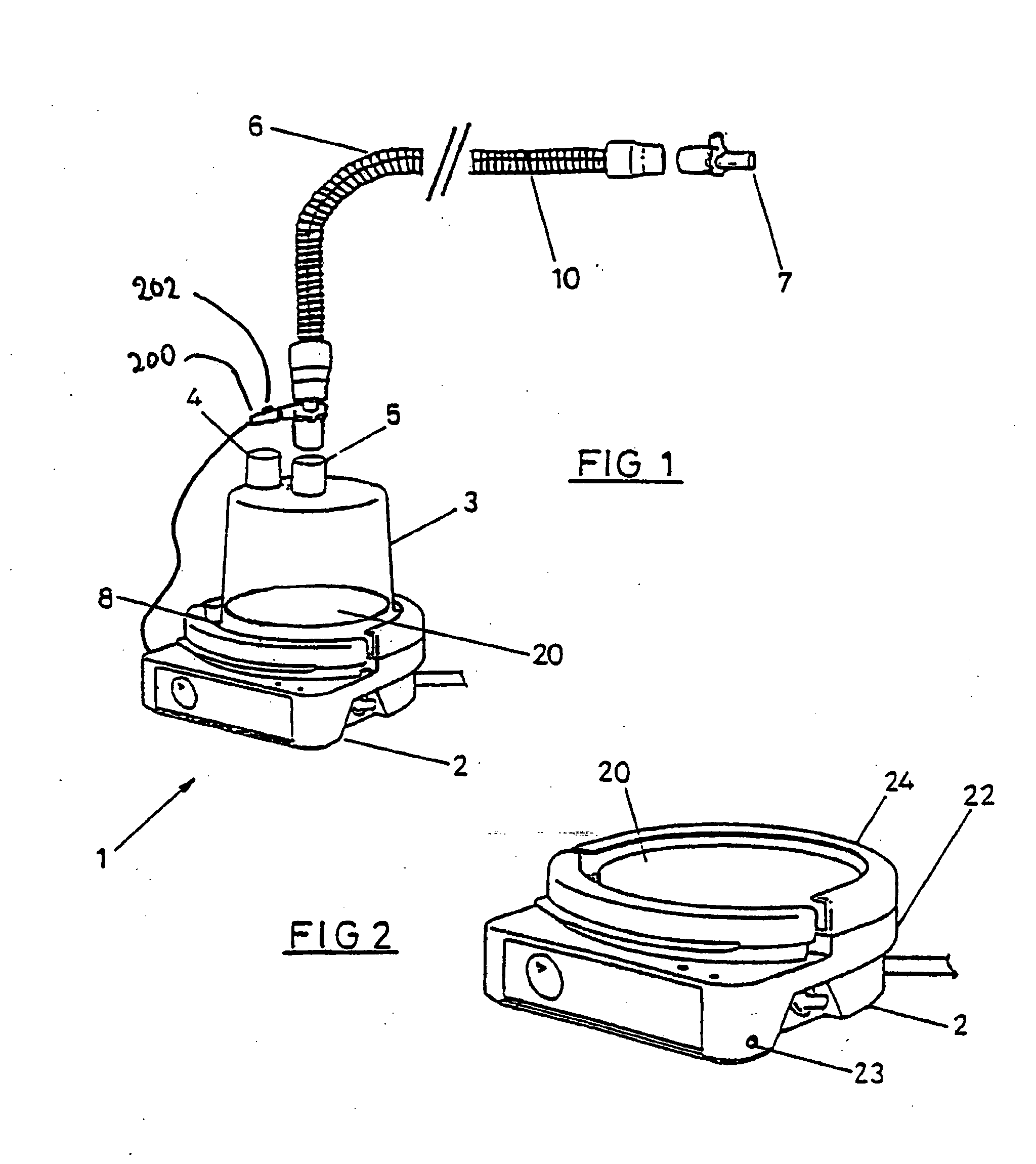
[0039] FIG. 1 is a illustration of a respiratory humidifier system,
[0040] FIG. 2 is a illustration of the humidifier base of the respiratory humidifier system of FIG. 1,
[0041] FIG. 3 is a block diagram of the control system which controls the humidifier in the preferred embodiment of the present invention,
[0042] FIG. 4 is a flow diagram of the algorithm used to control the heater wire within the respiratory conduit,
[0043] FIG. 5 is an example of how the heater plate temperature varies over time, when the pressure is controlled constant,
[0044] FIG. 6 is a graph of heater plate power against flow rate, and
[0045] FIG. 7 is a graph of conduit heater element power and flow rate.
DETAILED DESCRIPTION OF THE INVENTION
[0046] Whether used in a hospital environment or in a home care environment, the present invention will generally have associated two main pieces of apparatus. Firstly an active humidifier which controls the temperature of a heater plate heating a body of water to achieve a desired temperature and humidity of the gases being humidified. Secondly a transport conduit from the humidifier to the patient is also required, which is preferably heated to reduce condensation, or "rain out".
[0047] Referring to FIG. 1 a humidifying apparatus as might be used in a hospital generally referenced 1 is shown. The apparatus comprises a body 2 containing heating means comprising a heating plate 20 having an electric heating element therein or in thermal contact therewith and control means for example electronic circuitry which may include a microprocessor for controlling the supply of energy to the heating element. The body 2 is removably engageable with a. humidifying chamber 3 which contains water for humidifying gases. Referring to FIG. 2 which show the humidifier apparatus in more detail, the humidifying chamber 3 has edges which engage with collar 24 on the humidifier apparatus. The gases to be humidified may be a mixture of air, oxygen and anaesthetic for example which are supplied to the chamber through a gases inlet 4. This might be connected to a ventilator, or in the case of CPAP therapy a CPAP blower. A gases outlet 5 is also provided and the gases outlet 5 is connected to the conduit 6 (FIG. 1) which conveys humidified gases to a remote destination such as an intubated patient at the end 7 of the conduit. Alternatively, the end 7 of the conduit may have a gas mask attached thereto, which mask is used to cover a nose and/or mouth of a user so as to supply humidified gases to the user for breathing, as in the delivery of CPAP therapy. The humidifier heater plate 20 has a temperature transducer 8 which is in electrical connection with the electronic control circuitry in body 2 of the apparatus so that the control means monitors the temperature of the heating plate.
[0048] A heating element 10 is provided within the conduit 6 to help prevent condensation of the humidified gases within the conduit. Such condensation is due to the temperature of the walls of the conduit being close to the ambient temperature, (being the temperature of the surrounding atmosphere) which is usually lower than the temperature of the humidified gases within the conduit. The heater element is effectively replaces the energy lost from the gases through conduction and convection during transit through the conduit. Thus the conduit heater element ensures the gases delivered are at an optimal temperature and humidity.
[0049] The present invention provides a means of controlling at least the heater plate and preferably also the conduit heater element without the need for any sensors, either in the humidifier chamber or positioned in the conduit. This is achieved by estimating the rate of flow of gases through the humidifier using parameters already available to the controller. For a given humidifier an appropriate level of power can then be determined to apply to the heater plate to achieve the desired temperature of gases delivered to the patient. Additionally this may be used to provide a more appropriate level of energisation at this conduit heater element. This not only saves the cost of the extra sensors but also allows the apparatus connected to the end of the conduit to be simpler and lighter.
[0050] In the preferred embodiment of the present invention the controller 100, shown in FIG. 3, uses a range of inputs to control both the power 108 supplied to the heater plate 110 as well as the power 114 supplied to the conduit heating element 116 (if present). In certain applications it may also be used to provide control instructions to auxiliary apparatus such as a blower fan. Using an internal algorithm 106 the controller 100 estimates the power 108 to supply to the humidifier heater plate 110 to achieve a given humidity and or temperature of gases at the top of the humidifier chamber alternatively (or estimates the temperature to achieve a given power). It then uses a second algorithm 102 to estimate the required power 114 to supply to the conduit heater element 116 and the humidifier heater plate 110 to achieve optimal temperature and/or humidity of the gases delivered to the patient 118.
[0051] Referring to FIG. 4, when the humidifier starts up the controller executes a supervisory algorithm, which controls the heater plate and if present the conduit heater element. Initially 128 the heater plate is controlled to a temperature of 40.degree. C. and the conduit heater element may be energised with a duty cycle of for example 50%. The heater plate temperature (or alternatively the power supplied to the heater plate) is then monitored 130 until it settles to a stabilised level. Effectively a window 132 is superimposed over the heater plate temperature profile 134 of which an example is shown in FIG. 5. When the profile 134 (over the entire period of the window 132) fits within the bounds of the window 132, it is effectively considered to have stabilised. Once this has occurred the controller enters a calculation stage.
[0052] Firstly, it calculates the flow rate of the gases 136 using any one of a number of methods which will be described later.
[0053] Secondly knowing the rate of flow of the gases the algorithm then calculates the required heater plate power 138 (alternatively heater plate temperature) to achieve a desired temperature/humidity of gases (alternatively heater plate power). A relationship has been empirically determined using a humidifier and a heated conduit such as that as described in U.S. Pat. No. 5,640,951, the contents of which are incorporated herein by reference. The actual relationship for any other arrangement would either have to be empirically determined by experimentation or theoretically calculated. For a desired temperature of gases exiting the humidifier of for example 37.degree. C. the relationship between the power supplied to the heater plate (P.sub.HP), the rate of flow of gases (F.sub.gas) and the ambient temperature (T.sub.amb) is graphed in FIG. 6. From this an approximate general algebraic equation has been extrapolated which the controller can use to determine an approximate level of power to apply to the heater plate:
P.sub.HP=(-0.1239.times.T.sub.amb+5.383).times.F.sub.gas+(-0.3112.times.- T.sub.amb+10.738)
[0054] Thirdly the algorithm calculates the required power input to the conduit heater wire 140 to deliver a desired temperature of the gases to the patient. With gases flowing at a known rate of flow it is possible to calculate the resultant temperature of the gases once they have flowed through a conduit of known characteristics surrounded by the atmosphere at a known or assumed ambient temperature. Thermal characteristics of the conduit will either be known or can be calculated by experimentation. This relationship is based off empirical data using a humidifier and a heated conduit such as that as described in U.S. Pat. No. 5,640,951. The actual relationship for any other arrangement would either have to be empirically determined by experimentation or theoretically calculated. With a conduit entry gas temperature of 37.degree. C. and a temperature of gases delivered to the patient of 40.degree. C., the relationship between the flow rate of the gases (F.sub.gas), the power input to the conduit heater element (P.sub.c), the ambient temperature (T.sub.amb) is graphed in FIG. 7. This is extrapolated to a general algebraic expression:
P.sub.c=(-0.0005*T.sub.amb+0.0169) F.sub.gas.sup.2-[10.sup.-5*T.sub.amb.sup.3-0.0042*T.sub.amb.sup.2+0.2189*- T.sub.amb-3.0075]F.sub.gas-1.0169*T.sub.amb+38.956
Practically this relationship can be simplified whereby P.sub.c is dependent only on T.sub.amb. This is an acceptable approximation for the conduit heater element, as it is not as crucial as the heater plate.
[0055] Once the heater plate and conduit heater element have been appropriately energised, the controller continues to monitor 142 the system for any changes in the variables. The main reason for this is to avoid thermal overshoot i.e. where the flow drops suddenly, the temperature of gases can become dangerously high.
[0056] In order to monitor effectively, two methods are used. Firstly the flow rate is monitored and secondly the change in flow rate (with respect to time) is also monitored. The first 144 is to allow the system to respond to any changes in the system. The second 146 is a fast response system in order to avoid thermal overshoot. Effectively where either P.sub.HP or T.sub.HP is controlled constant, monitoring the other variable gives an indication of any change in flow, or any other variable which requires a recalculation.
[0057] In order to monitor the flow a variable x (defined as P.sub.HP/T.sub.HP), which is closely related to the flow rate, is constantly calculated and monitored. If it goes up there is a 30 minute delay before the controller initiates a recalculation, to avoid spurious readings and unnecessary calculations. If it goes down there is a 30 second delay before the controller recalculates, to avoid any possibility of the delivered gases being, even transiently, too hot.
[0058] Where large step changes occur the controller needs to react quickly. In such cases it will reset to initial conditions to wait until the system stabilises again, as any calculations in the interim would be pointless. To achieve this dx/dt is calculated and monitored. While a negative value is more dangerous, any deviation over a certain value will reset the controller.
[0059] In an alternative embodiment of the present invention the expected heater plate temperature is calculated using
T.sub.HP=-7.3319*Ln(F.sub.gas)+63.655
and if the actual heater plate temperature deviates by more than 5.degree. C. then the program recalculates the required powers.
[0060] Thus in summary controller carries out the following steps: [0061] 1) Estimates the rate of flow of gases keeping all variables constant 136. [0062] 2) Estimate the required heater plate power/temperature to achieve a specified temperature/humidity of gases in the humidification chamber 138. [0063] 3) Calculate the power input to the heater wire to achieve a desired output temperature 140.
[0064] It will be appreciated that a greater level of power will be supplied to the conduit heater element if: [0065] i) the rate of flow of the gases reduces, [0066] ii) the ambient temperature decreases, [0067] iii) the differential between ambient and gases temperature increases.
[0068] It will also be appreciated that the heater plate temperature could be controlled to a set valve (using closed loop control) as opposed to power. In this case the power supplied would be monitored as a measure of system stability. Furthermore where relationships are expressed algebraically they could equally be stored in look-up tables. First preferred embodiment of flow estimation
[0069] Generally when used in a hospital setting a humidifier such as that described in the present invention will be used in conjunction with a respirator to supply humidified gases to an incubated patient, or possibly using a respiratory mask. As such the humidifier will operate effective independently of the respirator and therefore must make all of its control decisions based on only the sensors contained therein. In the preferred embodiment of the present invention the flow rate of the gases passing through the humidification chamber can first be estimated by comparing the power input required 108 for the humidifier heater plate to the measured temperature 112 of the heater plate. In effect the higher the rate of flow of gases the larger the amount of power required by the heater plate in order to achieve a given heater plate temperature. Thus for a given system the relationship between power to heater plate and flow rate for a given heater plate temperature can either be determined empirically or theoretically calculated. Again using a humidifier and a heated conduit such as that as described in U.S. Pat. No. 5,640,951 the following empirically determined relationship applies:
F gas = - ( 0.831 - 0.0049 * T amb ) + abs ( 0.831 - 0.0049 * T amb ) 2 - ( 4 * ( 0.00004 * T amb - 0.0057 ) * ( ( 14.348 - 0.25 * T amb ) - P HP ) ) 2 * ( 0.0004 * T amb - 0.0057 ) ##EQU00001##
where P.sub.HP is the power applied to the heater plate to achieve a given heater plate temperature in steady state of 50.degree. C., T.sub.amb is the ambient temperature and F.sub.gas is the gas flow rate.
[0070] It will be appreciated this method is more appropriate in the hospital care environment where the ambient temperature can be assured with a high degree of confidence.
Second Preferred Embodiment of Flow Estimation
[0071] In the homecare environment the present invention will often be employed in conjunction with a continuous positive airway pressure (CPAP) device or such other breathing apparatus which will include a fan such as that described in U.S. Pat. No. 6,050,260, the contents of which are incorporated herein by reference. It will be appreciated that in such applications it may be possible to connect the controllers of the various devices together in an arrangement such that data may be readily exchanged. In such cases the rate of flow of the gases may be estimated directly from information available either from the fan or, where provided, a flow sensor.
[0072] In this embodiment of the present invention the flow is estimated based on the loading of the fan. Generally the fan will be controlled to run at a specified speed and therefore deliver a constant pressure output. The flow rate of the gases will depend on the restrictions in the flow path. In turn in order to maintain the specified speed a certain power input will be required for the fan. Therefore an algebraic relationship between the actual gas flow rate and the power input to the fan can be developed for a fan of known characteristics. This relationship may either be determined empirically by experimentation or theoretically calculated using specified motor characteristics.
[0073] A number of methods are known in the art for determining the loading on a motor from the supply it draws. The simplest such method would be to firstly meter the current drawn 148 from the fan 150, as indicated in FIG. 3. The current 148 is the input to the conduit heater element controller 102 where either an algebraic relationship or a look up table is used to determine the flow rate of the gases.
[0074] For example in U.S. Pat. No. 5,740,795, the contents of which are hereby incorporated herein by reference, a method is disclosed using both motor voltage and current to estimate the flow rate. While this represents one method, as mentioned above, it will be appreciated that other methods, such as based on just current, will be equally applicable.
Third Preferred Embodiment of Flow Estimation
[0075] As mentioned in the second embodiment that in certain cases a flow sensor may already be provided in the gas flow path. This being the case, the gas flow rate 152 can be extracted directly from the flow sensor 154 and used as an input to the humidifier controller 100, as indicated in FIG. 3. This is then used directly in the conduit heater element controller 102 to determine the power to apply to the heater plate 110 and conduit heater element 116 according to the algorithm shown in FIG. 4 and described earlier.
Heater Wire Adaptor
[0076] In order to connect the conduit heater element to the power supply in the humidifier, an adaptor cable is required. In the preferred embodiment of the present invention, the adaptor 200 includes an indicator 202 to indicate whether the conduit heater element is operating correctly, when the adaptor is plugged in, as shown in FIG. 1.
[0077] The humidifier controller continually detects for the conduit heater element and determines whether it is operating correctly. It does this by energising the conduit heater element intermittently, and if the expected current results it energises 204 the indicator (e.g. an LED).
[0078] The present invention as described in the foregoing provides a novel method and apparatus for controlling the heater plate temperature in a humidifier for supplying humidified gases to a patient under respiratory therapy. This has the advantage of removing external sensors making the system simpler, cheaper and lighter. Similarly it may also allow for effective control over energisation of the conduit heater element, ensuring the system as a whole operates correctly as well as being as efficient as possible.
* * * * *
uspto.report is an independent third-party trademark research tool that is not affiliated, endorsed, or sponsored by the United States Patent and Trademark Office (USPTO) or any other governmental organization. The information provided by uspto.report is based on publicly available data at the time of writing and is intended for informational purposes only.
While we strive to provide accurate and up-to-date information, we do not guarantee the accuracy, completeness, reliability, or suitability of the information displayed on this site. The use of this site is at your own risk. Any reliance you place on such information is therefore strictly at your own risk.
All official trademark data, including owner information, should be verified by visiting the official USPTO website at www.uspto.gov. This site is not intended to replace professional legal advice and should not be used as a substitute for consulting with a legal professional who is knowledgeable about trademark law.