Chair With A Footrest Device
Lin; Chang-Chen
U.S. patent application number 15/661010 was filed with the patent office on 2019-01-31 for chair with a footrest device. The applicant listed for this patent is Chang-Chen Lin. Invention is credited to Chang-Chen Lin.
| Application Number | 20190029436 15/661010 |
| Document ID | / |
| Family ID | 65138393 |
| Filed Date | 2019-01-31 |


| United States Patent Application | 20190029436 |
| Kind Code | A1 |
| Lin; Chang-Chen | January 31, 2019 |
Chair With A Footrest Device
Abstract
A chair includes a base having two sideboards. Each sideboard includes first and second coupling portions respectively at rear and front portions thereof. A seat is mounted on the base. A third coupling portion and a fourth coupling portion are provided on each lateral side of the seat. Each fourth coupling portion is coupled to one of the second coupling portions of the base. The seat is movable in a longitudinal direction and has a front end supported by the second and fourth coupling portions. A positioning device is coupled with the third coupling portion of the seat and the base, providing support for the rear end of the seat. The positioning device positions the seat relative to the base. A backrest is mounted to a rear of the base and is pivotably connected to the rear end of the seat and the sideboards.
| Inventors: | Lin; Chang-Chen; (Tainan City, TW) | ||||||||||
| Applicant: |
|
||||||||||
|---|---|---|---|---|---|---|---|---|---|---|---|
| Family ID: | 65138393 | ||||||||||
| Appl. No.: | 15/661010 | ||||||||||
| Filed: | July 27, 2017 |
| Current U.S. Class: | 1/1 |
| Current CPC Class: | A47C 1/03272 20130101; A47C 1/03294 20130101; A47C 7/50 20130101; A47C 1/143 20130101; A47C 7/34 20130101; A47C 7/40 20130101; A47C 1/0325 20130101; A47C 20/08 20130101 |
| International Class: | A47C 20/08 20060101 A47C020/08; A47C 7/34 20060101 A47C007/34; A47C 7/40 20060101 A47C007/40; A47C 7/50 20060101 A47C007/50 |
Claims
1. A chair with a footrest device, comprising: a base adapted to be placed on a ground, wherein the base includes two sideboards extending in a longitudinal direction and spaced from each other in a width direction perpendicular to the longitudinal direction, wherein each of the two sideboards extends in a vertical direction perpendicular to the ground and the longitudinal direction and includes a front end and a rear end spaced from the front end in the longitudinal direction, wherein a front board is interconnected between the front ends of the two sideboards, wherein a rear board is interconnected between the rear ends of the two sideboards, wherein each of the two sideboards further includes a first coupling portion at a rear portion thereof substantially aligned with a buttock of a sitter sitting in the chair, wherein each of the two sideboards further includes a second coupling portion at a front portion thereof substantially aligned with two feet of the sitter, wherein each of the two sideboards further includes a pivotal seat on an inner face of the rear end thereof, and wherein each pivotal seat includes a first pivotal portion; a seat mounted on top of the base, wherein the seat includes a front end and a rear end having a second pivotal portion, wherein the seat has a length in the longitudinal direction for supporting the buttock and two legs of the sitter, wherein the seat further includes two lateral sides, wherein each of the two lateral sides of the seat includes a third coupling portion aligned with the first coupling portion and a fourth coupling portion aligned with the second coupling portion, wherein each fourth coupling portion is coupled to one of the second coupling portions of the base, wherein the seat is movable in the longitudinal direction, wherein the front end of the seat is supported by the second and fourth coupling portions; a positioning device coupled with the third coupling portion of the seat and the base, providing support for the rear end of the seat, wherein the positioning device positions the seat relative to the base; and a backrest mounted to a rear of the base, wherein the backrest includes a lower end having a third pivotal portion pivotably connected to the second pivotal portion of the seat, wherein the backrest further includes two lateral sides, wherein each of the two lateral sides of the backrest includes a fourth pivotal portion at a lower portion thereof, and wherein each fourth pivotal portion is pivotably connected to one of the first pivotal portions of the base.
2. The chair with a footrest device as claimed in claim 1, wherein each first coupling portion of the base includes a first through-hole, wherein the positioning device includes two rear guiding rods, two locking seats, and two control knobs, wherein each of the two rear guiding rods includes a front end pivotably connected to one of the third coupling portions of the seat, wherein each of the two rear guiding rods is slideably received in one of the two locking seats, wherein each of the two locking seats is switchable between a locking position in which a corresponding one of the two rear guiding rods is locked in place and an unlocking position permitting sliding movement of the corresponding one of the two rear guiding rods, wherein each of the two locking seats includes a follower rod at an outer side thereof, wherein each of the two control knobs is mounted outside of one of the first coupling portions of the base and includes a coupling rod extending through the first through-hole of one of the first coupling portions and coupled with the follower rod of one of the two locking seats, and wherein each of the two control knobs is operable to switch one of the two locking seats between the locking position and the unlocking positions.
3. The chair with a footrest device as claimed in claim 2, wherein each third coupling portion of the seat includes an engaging plate having a pivotal hole, wherein the front end of each of the two rear guiding rods includes a pivotal hole, wherein two pivots are respectively extended through the pivotal holes of the third coupling portions and the pivotal holes of the two rear guiding rods.
4. The chair with a footrest device as claimed in claim 2, wherein each first coupling portion of the base further includes a first plate having a strength greater than the two sideboards of the base, wherein each first plate is fixed on an inner face of one of the two sideboards, and wherein each first through-hole extends through one of the first plates.
5. The chair with a footrest device as claimed in claim 1, wherein each pivotal seat includes an opening in an upper end thereof, wherein each third pivotal portion of the backrest is mounted below one of the pivotal seats, wherein each fourth pivotal portion includes a pivot inserted into the opening and pivotably connected to the first pivotal portion of one of the pivotal seats of the base.
6. The chair with a footrest device as claimed in claim 1, wherein each second coupling portion of the base includes a second plate harder than the two sideboards, wherein each second plate is fixed on an inner face of one of the two sideboards, wherein each second plate includes a coupling tube formed on an inner face of the second plate, wherein each fourth coupling portion of the seat includes a front guiding rod extending in the longitudinal direction and a coupling seat mounted around the front guiding rod, wherein each front guiding rod includes two ends fixed to the seat, wherein each coupling seat has a connecting rod extending through the coupling tube of one of the second coupling portions of the base, and wherein each front guiding rod slides in a corresponding one of the coupling seats when the seat moves in the longitudinal direction.
7. The chair with a footrest device as claimed in claim 2, further comprising at least one elastic element, wherein the at least one elastic element provides resistance to forward movement of the seat in the longitudinal direction and provides an elastic returning force for moving the seat rearward.
8. The chair with a footrest device as claimed in claim 7, wherein the base includes at least one fifth coupling portion, wherein the positioning device includes at least one sixth coupling portion on at least one of the rear ends of the two rear guiding rods, wherein the at least one elastic element is a coil spring and has two tangs and respectively connected to the at least one fifth coupling portion and the at least one sixth coupling portion.
Description
BACKGROUND OF THE INVENTION
[0001] The present invention relates to a chair with a footrest device and, more particularly, to a chair with a footrest device providing improved lying applicability and improved lying comfort for the back of a sitter.
[0002] Conventional chairs generally include a seat, a backrest, and a leg for supporting the seat at a proper height above the ground, such that the feet of the sitter can rest on the ground and that the back of the sitter can lay against the backrest to keep the head of the sitter in an upright position. The angle between the backrest and the seat can be adjusted to improve the sitting comfort.
[0003] However, the center of the gravity of the sitter in the sitting position generally lies in the buttock portion. After long-term sitting, the sitter feels uncomfortable at the buttock subject to force. FIG. 7 shows a conventional chair including a base 2' and a seat 1' mounted on top of the base 2'. The seat 1' has a length for supporting the buttock and the feet of the sitter. Furthermore, a backrest 21' extends upright from a rear end of the base 2' for supporting the back of the sitter. Thus, the buttock and the legs of the sitter supports the weight of the sitter, and the sitter can stretch out the legs to make himself or herself comfortable. Furthermore, the sitter can lay the back against the backrest 21' to keep the head upright. However, the backrest 21' cannot be adjusted in the angular position relative to the base 2' and, thus, provides limited lying comfort.
[0004] In a design shown in FIG. 8 for solving the above disadvantage, the seat 1' includes a bent portion 11' at the rear end of thereof. A telescopic rod 12' is mounted between the bent portion 11' and the base 2', such that the bent portion 11' can be moved upward to an inclined position for supporting the back of the sitter, improving the lying comfort at the back. However, when the bent portion 11' is in the inclined position, the remaining length L of the seat 1' in the longitudinal direction is too small to support the buttocks and the legs of the sitter.
BRIEF SUMMARY OF THE INVENTION
[0005] An objective of the present invention is to provide a chair with a footrest device providing improved lying applicability and improved lying comfort for the back of the sitter.
[0006] A chair with a footrest device according to the present invention includes a base adapted to be placed on the ground. The base includes two sideboards extending in a longitudinal direction and spaced from each other in a width direction perpendicular to the longitudinal direction. Each of the two sideboards extends in a vertical direction perpendicular to the ground and the longitudinal direction and includes a front end and a rear end spaced from the front end in the longitudinal direction. A front board is interconnected between the front ends of the two sideboards. A rear board is interconnected between the rear ends of the two sideboards. Each of the two sideboards further includes a first coupling portion at a rear portion thereof substantially aligned with a buttock of a sitter sitting in the chair. Each of the two sideboards further includes a second coupling portion at a front portion thereof substantially aligned with two feet of the sitter. Each of the two sideboards further includes a pivotal seat on an inner face of the rear end thereof, and each pivotal seat includes a first pivotal portion. A seat is mounted on top of the base. The seat includes a front end and a rear end having a second pivotal portion. The seat has a length in the longitudinal direction for supporting the buttock and two legs of the sitter. The seat further includes two lateral sides. Each of the two lateral sides of the seat includes a third coupling portion aligned with the first coupling portion and a fourth coupling portion aligned with the second coupling portion. Each fourth coupling portion is coupled to one of the second coupling portions of the base. The seat is movable in the longitudinal direction. The front end of the seat is supported by the second and fourth coupling portions. A positioning device is coupled with the third coupling portion of the seat and the base, providing support for the rear end of the seat. The positioning device positions the seat relative to the base. A backrest is mounted to a rear of the base. The backrest includes a lower end having a third pivotal portion pivotably connected to the second pivotal portion of the seat. The backrest further includes two lateral sides. Each of the two lateral sides of the backrest includes a fourth pivotal portion at a lower portion thereof. Each fourth pivotal portion is pivotably connected to one of the first pivotal portions of the base.
[0007] In an example, each first coupling portion of the base includes a first through-hole. The positioning device includes two rear guiding rods, two locking seats, and two control knobs. Each of the two rear guiding rods includes a front end pivotably connected to one of the third coupling portions of the seat. Each of the two rear guiding rods is slideably received in one of the two locking seats. Each of the two locking seats is switchable between a locking position in which a corresponding one of the two rear guiding rods is locked in place and an unlocking position permitting sliding movement of the corresponding one of the two rear guiding rods. Each of the two locking seats includes a follower rod at an outer side thereof. Each of the two control knobs is mounted outside of one of the first coupling portions of the base and includes a coupling rod extending through the first through-hole of one of the first coupling portions and coupled with the follower rod of one of the two locking seats. Each of the two control knobs is operable to switch one of the two locking seats between the locking position and the unlocking positions.
[0008] In an example, each third coupling portion of the seat includes an engaging plate having a pivotal hole. The front end of each of the two rear guiding rods includes a pivotal hole. Two pivots are respectively extended through the pivotal holes of the third coupling portions and the pivotal holes of the two rear guiding rods.
[0009] In an example, each first coupling portion of the base further includes a first plate having a strength greater than the two sideboards of the base. Each first plate is fixed on an inner face of one of the two sideboards. Each first through-hole extends through one of the first plates.
[0010] In an example, each pivotal seat includes an opening in an upper end thereof. Each third pivotal portion of the backrest is mounted below one of the pivotal seats. Each fourth pivotal portion includes a pivot inserted into the opening and pivotably connected to the first pivotal portion of one of the pivotal seats of the base.
[0011] In an example, each second coupling portion of the base includes a second plate harder than the two sideboards. Each second plate is fixed on the inner face of one of the two sideboards. Each second plate includes a coupling tube formed on an inner face of the second plate. Each fourth coupling portion of the seat includes a front guiding rod extending in the longitudinal direction and a coupling seat mounted around the front guiding rod. Each front guiding rod includes two ends fixed to the seat. Each coupling seat has a connecting rod extending through the coupling tube of one of the second coupling portions of the base. Each front guiding rod slides in a corresponding one of the coupling seats when the seat moves in the longitudinal direction.
[0012] In an example, the chair with a footrest device further comprises at least one elastic element. The at least one elastic element provides resistance to forward movement of the seat in the longitudinal direction and provides an elastic returning force for moving the seat rearward.
[0013] In an example, the base includes at least one fifth coupling portion. The positioning device includes at least one sixth coupling portion on at least one of the rear ends of the two rear guiding rods. The at least one elastic element is a coil spring and has two tangs and respectively connected to the at least one fifth coupling portion and the at least one sixth coupling portion.
[0014] In use of the chair according to present invention, the sitter can lay his or her back against the backrest to keep his or head in an upright position during sitting. Furthermore, the buttock and the feet of the sitter can rest on the seat and can support the weight of the sitter, providing sitting comfort.
[0015] The control knobs can be operated to switch the locking seats to the unlocking position to thereby release the rear guiding rods while changing the rearward inclination angle of the backrest. When the backrest inclines rearward, the seat moves forward relative to the base, and the front guiding rods and the rear guiding rods move relative to the coupling seats and the locking seats while stretching the at least one elastic element, providing stable movement at the front and rear portions. Furthermore, the at least one elastic element provides appropriate resistance to the forward movement of the seat to avoid rapid forward movement, increasing sitting safety. Furthermore, after adjustment, the control knobs are used to switch the locking seats to the locking position to lock the rear guiding rods, to retain the angular position of the backrest, and to retain the position of the seat, providing improved lying comfort. Furthermore, the first and second coupling portions at the rear and front ends of the base provide a better supporting effect for the seat. Furthermore, the elastic returning force of the at least one elastic element moves the seat rearward, providing increased operational convenience.
[0016] The present invention will become clearer in light of the following detailed description of illustrative embodiments of this invention described in connection with the drawings.
DESCRIPTION OF THE DRAWINGS
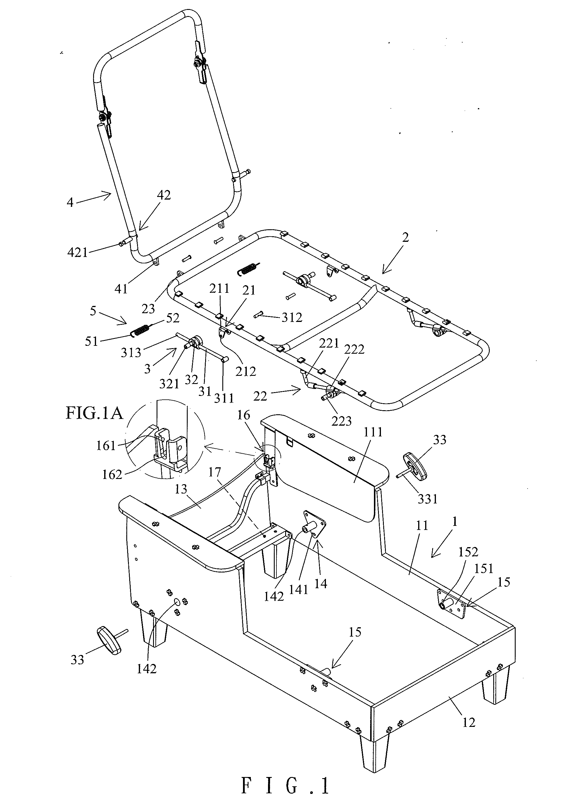
[0017] FIG. 1 is an exploded, perspective view of a chair with a footrest device according to the present invention.
[0018] FIG. 1A is an enlarged view of a circled portion of the chair of FIG. 1.
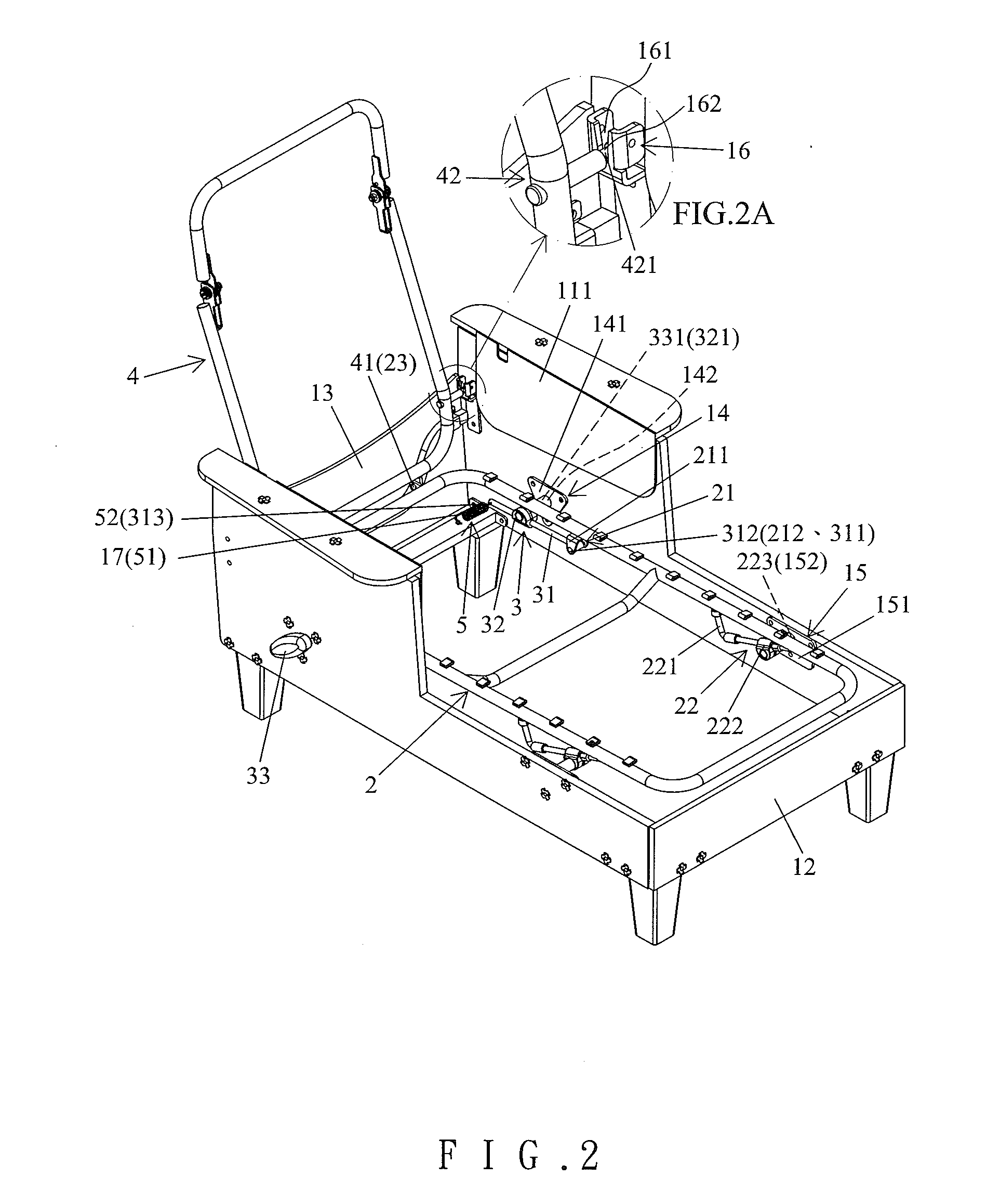
[0019] FIG. 2 is a perspective view of the chair of FIG. 1 after assembly, with a backrest of the chair not inclined rearward.
[0020] FIG. 2A is an enlarged view of a circled portion of the chair of FIG. 2.
[0021] FIG. 3 is a top view of the chair of FIG. 2.
[0022] FIG. 4 is a longitudinal cross sectional view of the chair of FIG. 3.
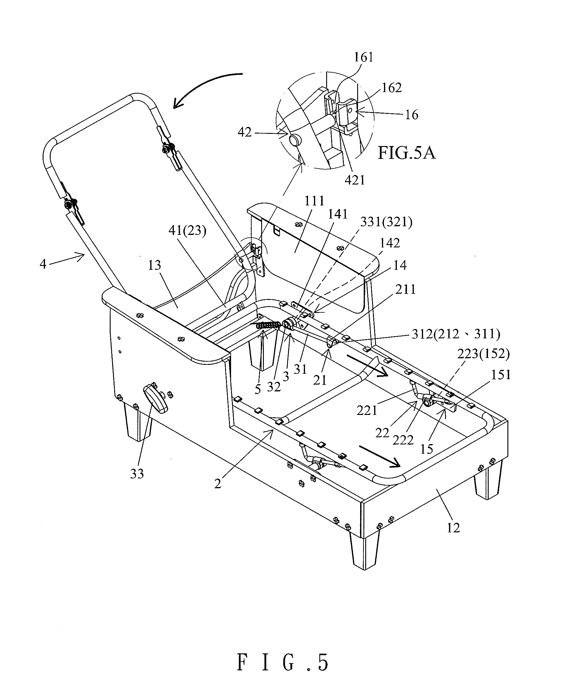
[0023] FIG. 5 is a perspective view similar to FIG. 2, with the backrest inclined rearward.
[0024] FIG. 5A is an enlarged view of a circled portion of the chair of FIG. 5.
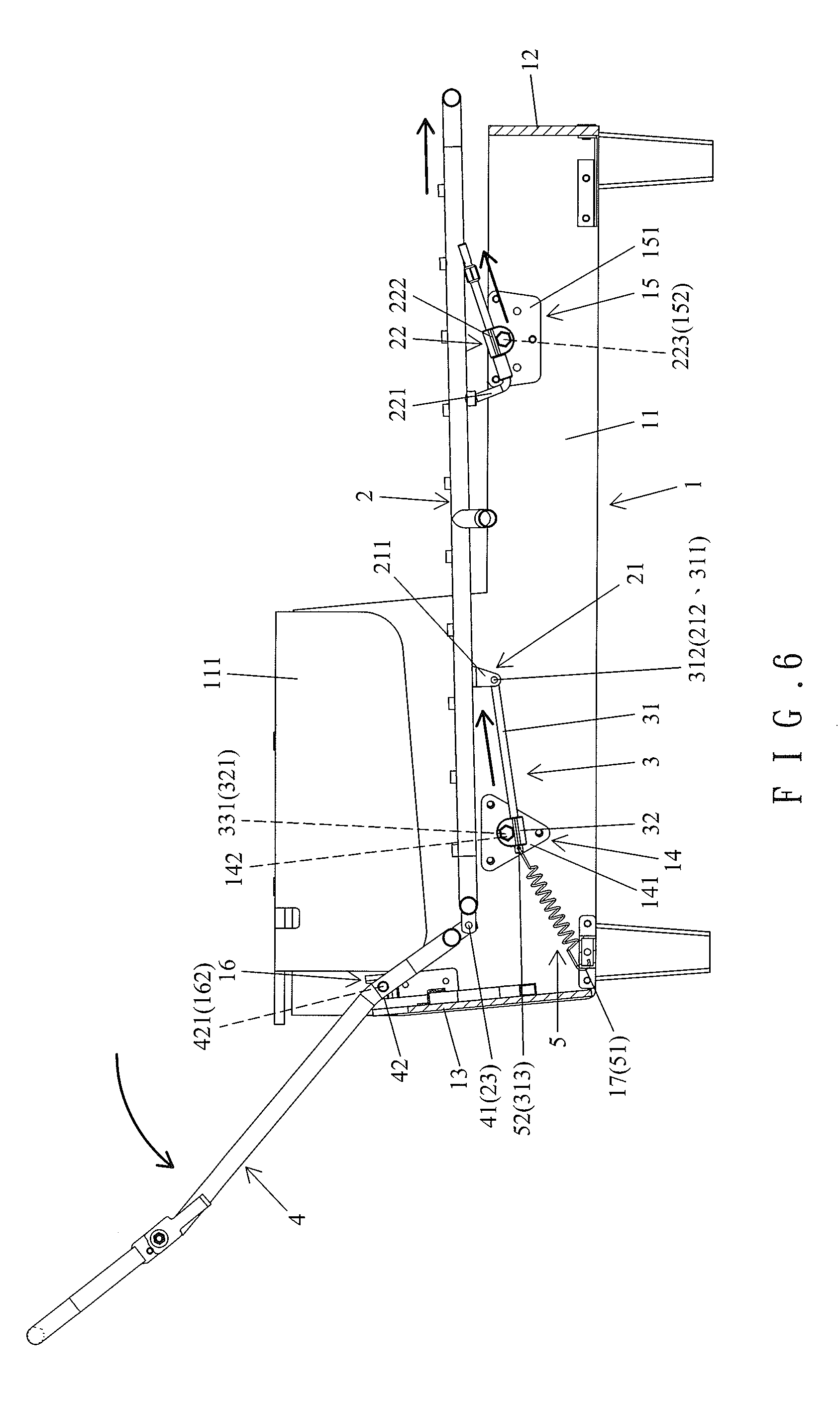
[0025] FIG. 6 is a view similar to FIG. 4, with the backrest inclined rearward.
[0026] FIG. 7 is a perspective view of a conventional chair.
[0027] FIG. 8 is a view similar to FIG. 7, with a rear portion of a seat pivoted upward.
DETAILED DESCRIPTION OF THE INVENTION
[0028] With reference to FIGS. 1-4, a chair with a footrest device of an embodiment according to the present invention includes a base 1, a seat 2, a positioning device 3, a backrest 4, and two elastic devices 5. The base 1 is adapted to be placed on the ground and is made of wood or another appropriate material. The base 1 includes two sideboards 11 extending in a longitudinal direction and spaced from each other in a width direction perpendicular to the longitudinal direction. Each of the two sideboards 11 extends in a vertical direction perpendicular to the ground and the longitudinal direction and includes a front end and a rear end spaced from the front end in the longitudinal direction. A front board 12 is interconnected between the front ends of the two sideboards 1. A rear board 13 is interconnected between the rear ends of the two sideboards 1. Each of the two sideboards 11 includes an armrest 111 extending upward from the rear end thereof. Each of the two sideboards 11 further includes a first coupling portion 14 at a rear portion thereof substantially aligned with a buttock of a sitter sitting in the chair. Each of the two sideboards 11 further includes a second coupling portion 15 at a front portion thereof substantially aligned with two feet of the sitter. Each first coupling portion 14 includes a first plate 141 made by metal or a material having a strength greater than the two sideboards 11. Each first plate 141 is fixed on an inner face of one of the two sideboards 11. Each first through-hole 142 extends through one of the first plates 141 and one of the sideboards 11. Each second coupling portion 15 of the base 1 includes a second plate 151 made of metal or a rigid material harder than the two sideboards 11. Each second plate 151 is fixed on the inner face of one of the two sideboards 11. Each second plate 151 includes a coupling tube 152 formed on an inner face thereof. Each of the two sideboards 11 further includes a pivotal seat 16 on an inner face of the rear end thereof. Each pivotal seat 16 includes an opening 161 in an upper end thereof. Each pivotal seat 16 includes a first pivotal portion 162 at a lower end thereof. The base 1 further includes two fifth coupling portions 17 at the rear end thereof.
[0029] The seat 2 is mounted on top of the base 1 and has a length in the longitudinal direction for supporting the buttock and two legs of the sitter. Each of the two lateral sides of the seat 2 includes a third coupling portion 21 aligned with the first coupling portion 14 and a fourth coupling portion 22 aligned with the second coupling portion 15. Each third coupling portion 21 includes an engaging plate 211 having a pivotal hole 212. Each fourth coupling portion 22 includes a front guiding rod 221 extending in the longitudinal direction and a coupling seat 222 mounted around the front guiding rod 221. Each front guiding rod 221 includes two ends fixed to the seat 2. Each coupling seat 222 has a connecting rod 223 extending through the coupling tube 152 of one of the second coupling portions 15 of the base 1. Each front guiding rod 221 slides in a corresponding one of the coupling seats 222 when the seat 2 moves in the longitudinal direction. The seat 2 further includes a front end and a rear end having a second pivotal portion 23.
[0030] The positioning device 3 positions the seat 2 relative to the seat 1 and retains the angular position of the backrest 4. The positioning device 3 includes two rear guiding rods 31, two locking seats 32, and two control knobs 33. Each rear guiding rod 31 includes a front end having a pivotal hole 311. The front ends of the two rear guiding rods 31 are placed in the coupling plates 211 of the third coupling portions 21 of the seat 2. Two pivots 312 are respectively extended through the pivotal holes 212 of the third coupling portions 21 and the pivotal holes 311 of the two rear guiding rods 31. Each of rear ends of the two rear guiding rods 31 includes a sixth coupling portion 313. Each of the two rear guiding rods 31 is slideably received in one of the two locking seats 32. Each of the two locking seats 32 is switchable between a locking position in which a corresponding one of the two rear guiding rods 31 is locked in place and an unlocking position permitting sliding movement of the corresponding one of the two rear guiding rods 31. The coupling arrangement between each locking seat 32 and the corresponding rear guiding rod 31 can be frictional coupling, gear meshing, a coupling mechanism disclosed in Taiwan Utility Model M370354 and M351652, or any other suitable provision. Furthermore, each of the two locking seats 32 includes a follower rod 321 at an outer side thereof. Each of the two control knobs 33 is mounted outside of one of the first coupling portions 14 of the base 1 and includes a coupling rod 331 extending through the first through-hole 142 of one of the first coupling portions 14 and coupled with the follower rod 321 of one of the two locking seats 32. Each of the two control knobs 33 is operable to switch one of the two locking seats 32 between the locking position and the unlocking positions.
[0031] The backrest 4 is mounted to a rear of the base 1. The backrest 4 includes a lower end having a third pivotal portion 41 pivotably connected to the second pivotal portion 23 of the seat 2. The backrest 4 further includes two lateral sides. Each of the two lateral sides of the backrest 4 includes a fourth pivotal portion 42 at a lower portion thereof. Each fourth pivotal portion 42 is pivotably connected to one of the first pivotal portions 162 of the base 1. Each fourth pivotal portion 42 includes a pivot 421 inserted into the opening 16 and pivotably connected to the first pivotal portion 162 of one of the pivotal seats 16 of the base 1.
[0032] Each elastic element 5 is a coil spring and has two tangs 51 and 52 respectively connected to one of the fifth coupling portions 17 and one of the sixth coupling portions 313.
[0033] The base 1, the seat 2, the positioning device 3, and the backrest 4 of the chair according to the present invention can be disassembled to reduce the packaging volume. Furthermore, after assembly of the seat 2 and the base 1, the pivots 421 of the backrest 4 can be inserted into the pivotal seats 16 of the base 1 to provide a local positioning effect. Then, the second and third coupling portions 23 and 41 can be coupled with each other to provide easy assembly.
[0034] In use of the chair according to present invention, the sitter can lay his or her back against the backrest 4 to keep his or head in an upright position during sitting. Furthermore, the buttock and the feet of the sitter can rest on the seat 2 and can support the weight of the sitter, providing sitting comfort.
[0035] The control knobs 33 can be operated to switch the locking seats 32 to the unlocking position to thereby release the rear guiding rods 31 while changing the rearward inclination angle of the backrest 4. With reference to FIGS. 5 and 6, when the backrest 4 inclines rearward, the seat 2 moves forward relative to the base 1, and the front guiding rods 221 and the rear guiding rods 31 move relative to the coupling seats 222 and the locking seats 32 while stretching the elastic elements 5, providing stable movement at the front and rear portions. Furthermore, the elastic elements 5 provide appropriate resistance to the forward movement of the seat 2 to avoid rapid forward movement, increasing sitting safety. Furthermore, after adjustment, the control knobs 33 are used to switch the locking seats 32 to the locking position to lock the rear guiding rods 31, to retain the angular position of the backrest 2, and to retain the position of the seat 2, providing improved lying comfort. Furthermore, the first and second coupling portions 14 and 15 at the rear and front ends of the base 1 provide a better supporting effect for the seat 2.
[0036] In view of the foregoing, in use of the chair according to the present invention, the buttock and the feet of the sitter can rest on the seat. Furthermore, the first and second coupling portions 14 and 15 at the rear and front ends of the base 1 provide a better supporting effect for the seat 2. Furthermore, the angular position of the backrest 4 can be easily adjusted without bending the seat 2 in the conventional arrangement, such that the seat 2 can still provide a sufficient area for supporting the buttock and the feet of the sitter even though the backrest 4 is inclined rearward. Furthermore, when the control knobs 3 are released, the elastic returning force of the elastic elements 5 moves the seat 2 rearward, providing increased operational convenience.
[0037] Although specific embodiments have been illustrated and described, numerous modifications and variations are still possible without departing from the scope of the invention. The scope of the invention is limited by the accompanying claims.
* * * * *
D00000
D00001
D00002
D00003
D00004
D00005
D00006
D00007
D00008
XML
uspto.report is an independent third-party trademark research tool that is not affiliated, endorsed, or sponsored by the United States Patent and Trademark Office (USPTO) or any other governmental organization. The information provided by uspto.report is based on publicly available data at the time of writing and is intended for informational purposes only.
While we strive to provide accurate and up-to-date information, we do not guarantee the accuracy, completeness, reliability, or suitability of the information displayed on this site. The use of this site is at your own risk. Any reliance you place on such information is therefore strictly at your own risk.
All official trademark data, including owner information, should be verified by visiting the official USPTO website at www.uspto.gov. This site is not intended to replace professional legal advice and should not be used as a substitute for consulting with a legal professional who is knowledgeable about trademark law.