Case For Cosmetic Products
Carraro; Daniel
U.S. patent application number 16/051312 was filed with the patent office on 2019-01-31 for case for cosmetic products. The applicant listed for this patent is ALBEA SERVICES. Invention is credited to Daniel Carraro.
| Application Number | 20190029392 16/051312 |
| Document ID | / |
| Family ID | 60450776 |
| Filed Date | 2019-01-31 |


| United States Patent Application | 20190029392 |
| Kind Code | A1 |
| Carraro; Daniel | January 31, 2019 |
CASE FOR COSMETIC PRODUCTS
Abstract
A cosmetic case includes a base, a cover, a seal and a closing/opening means, the base and the cover being hinged against each other via a pivot connection, the case being capable of occupying two separate positions, a closed position and an open position. The closing/opening means includes an additional part which is in slide connection or in pivot connection with the cover, and one or more locking means connected to the additional part, respectively to the base, the locking means forming a multipoint locking applying a sufficient pressure on a seal when the case is in the closed position such that the sealing against impurities and fluids between the inner and outer environments of the case, in the closed position, is total under the normal temperature and pressure conditions (NTPC), the seal being presented in the form of a material strand.
| Inventors: | Carraro; Daniel; (Asnieres sur Seine, FR) | ||||||||||
| Applicant: |
|
||||||||||
|---|---|---|---|---|---|---|---|---|---|---|---|
| Family ID: | 60450776 | ||||||||||
| Appl. No.: | 16/051312 | ||||||||||
| Filed: | July 31, 2018 |
| Current U.S. Class: | 1/1 |
| Current CPC Class: | A45D 40/22 20130101; A45D 33/24 20130101; A45D 2040/225 20130101; A45D 33/22 20130101; A45D 2200/051 20130101; A45D 33/008 20130101 |
| International Class: | A45D 33/00 20060101 A45D033/00; A45D 33/22 20060101 A45D033/22 |
Foreign Application Data
| Date | Code | Application Number |
|---|---|---|
| Jul 31, 2017 | FR | 1757326 |
Claims
1. A cosmetic case comprising a base, a cover, a seal and a closing/opening means, the base and the cover being hinged with respect to one another by means of a pivot connection, the case being capable of occupying two separate positions, a closed position wherein the cover is held in position on the base by the closing/opening means and an open position wherein the cover is free to pivot with respect to the base, said closing/opening means comprising: an additional part which is in slide connection or in pivot connection with the cover, a plurality of locking means connected to the additional part, respectively to the base, said locking means being designed to each cooperate with a housing provided in/on the base, respectively in/on the additional part, the plurality of locking means forming, with said housings, a multipoint locking, the seal being provided on the surface of the base, respectively of the cover, so as to undergo flattening by the cover, respectively by the base, when the case is in the closed position, wherein the multipoint locking applies sufficient pressure on the seal when the case is in the closed position such that the sealing against impurities and fluids between the inner and outer environments of said case, in the closed position, is total under the normal temperature and pressure conditions (NTPC).
2. The case according to claim 1, wherein the actuation of the closing/opening means is achieved by moving the additional part with respect to the cover so as to engage/disengage the locking means from their respective housing, such that the passage from the open position to the closed position of the case, and conversely, does not provoke any friction on the seal.
3. The case according to claim 1, wherein the connection between the additional part and the cover is ensured by a cooperation of technical forms present, on the one hand, over the outer periphery of the cover and, on the other hand, over an inner circumference of the additional part, the locking means and their respective housing being regularly distributed over the outer periphery of the cover and/or over the inner circumference of the additional part.
4. The case according to claim 1, wherein the seal is presented in the form of a material strand.
5. The case according to claim 1, wherein the seal is returned to the surface of the base, conversely to the surface of the cover.
6. The case according to claim 5, wherein the seal is held in position by surface gluing.
7. The case according to claim 1, wherein the seal is over-molded with the base, conversely with the cover.
8. The case according to claim 3, further comprising a means for assisting the opening of the case intended to automatically remove the cover from the base during the passage of the case from the closed position to the open position, without requiring the exterior user to intervene.
9. The case according to claim 8, wherein the seal serves as a means for assisting the opening.
10. The case according to claim 1, wherein the locking means are hooks.
11. The case according to claim 10, wherein the hooks have a technical form comprising a slope intended to facilitate the entry of said hooks into their respective housing during the passage from the open position to the closed position of the case.
12. The case according to claim 1, wherein the base is adapted to receive: a cosmetic product, in particular comprising a volatile and/or damp composition, and a cosmetic product applicator, and wherein the cover is structured to receive a mirror of the pocket mirror type.
Description
CROSS-REFERENCE TO RELATED APPLICATIONS
[0001] This application claims priority under 35 U.S.C. 119(a) to French Patent Application No. 1757326, filed Jul. 31, 2017.
BACKGROUND OF THE INVENTION
Field of the Invention
[0002] The invention relates to a case for cosmetic products. Such cases usually include a base for receiving cosmetic products and a cover to close or open the case. Thus, when the cover is in an open position, the user has access to the base.
Description of the Related Art
[0003] Generally, cases for cosmetic products include a housing configured to receive the cosmetic product and a cover. The cover is conventionally closed by clipping or screwing. In the closed position, the cover protects the cosmetic product and the opening thereof enables the user to access the cosmetic product which is located in the housing.
[0004] To obtain a sufficient sealing against impurities and fluids between the inner and outer environments of the case, it is recommended to use a seal, in particular if this relates to a cosmetic product including a volatile and/or damp composition. Generally, the seal is arranged between the base and the cover and it undergoes flattening when the case is in the closed position.
[0005] Generally, the locking is done by a locking system, such as a pushbutton, in one single point placed on the front of the case. The pressure exerted on the seal is thus not consistent over the whole surface of the seal, in particular behind the case. The sealing is thus not sufficiently effective and the cosmetic product risks being damaged quickly or pouring out.
[0006] In addition, in this type of case, the presence of the seal creates additional pressure, and locking/unlocking can thus be more difficult to achieve.
[0007] In the case, for example, of cases closed by screwing, when the case goes from the open position to the closed position and vice versa, this in particular leads to friction on the seal. After several openings/closings, a premature wear on the seal is observed, the sealing is damaged and the case is no longer sufficiently sealed. The cosmetic product thus risks accelerated ageing. In addition, it is not possible to reuse the product, once the cosmetic product is finished, as the sealing is no longer effective.
[0008] Therefore, there is a need for a case for cosmetic products enabling to resolve the preceding disadvantages and which has a simple design that is easy to use.
BRIEF SUMMARY OF THE INVENTION
[0009] For this purpose, the present invention proposes a cosmetic case including a base, a cover, a seal and a closing/opening means.
[0010] The base and the cover are hinged against each other via a pivot connection. The case is capable of occupying two separate positions, a closed position wherein the cover is held in position on the base by the closing/opening means and an open position wherein the cover is free to pivot with respect to the base.
[0011] The closing/opening means includes: [0012] an additional part which is in slide connection or in pivot connection with the cover, [0013] a plurality of locking means connected to the additional part--respectively to the base, the locking means being designed to each cooperate with a housing provided in/on the base--respectively in/on the additional part, the plurality of locking means forming, with the housings, a multipoint locking.
[0014] The seal is provided on the surface of the base--respectively of the cover--so as to undergo flattening by the cover--respectively by the base--when the case is in the closed position.
[0015] The multipoint locking applies sufficient pressure on the seal when the case is in the closed position such that the sealing against impurities and fluids between the inner and outer environments of the case, in the closed position, is total under the normal temperature and pressure conditions (NTPC). In other words, the multipoint locking is configured to apply a pressure on the seal such that, in the closed position, the case is closed so as it is sealed, that is to say, with a sealing against the impurities and fluids between the inner and outer environments of the case which is total under the normal temperature and pressure conditions (NTPC).
[0016] Contrary to the conventional case, the case according to the invention includes an additional part, mobile with respect to the cover.
[0017] On the one hand, this additional part enables the use of a multipoint locking. Such a multipoint locking enables a distribution of the pressure exerted on the seal. The sealing is thus effective and sufficient at any point of the seal, both for dust particles and for a liquid.
[0018] On the other hand, the presence of the additional part enables an opening of the case by applying a more significant force, thus a seal can be added without this complicating the locking and unlocking of the case.
[0019] Moreover, the presence of the additional part avoids having friction between the cover and the base. Thus, the passage from the closed position to the open position of the case and vice versa, does not lead to premature wear of the seal. The cosmetic product does not therefore risk being damaged prematurely.
[0020] Moreover, once the cosmetic product is finished, the sealing is still effective and the case remains operational to receive an amount of additional cosmetic product, to be refilled with cosmetic product.
[0021] According to different embodiments of the invention, which can be taken together or separately: [0022] the actuation of the closing/opening means is done by the moving of the additional part with respect to the cover so as to engage/disengage the locking means of their respective housing, such that the passage from the open position to the closed position of the case, and conversely, does not provoke any friction on the seal, [0023] the connection between the additional part and the cover is ensured by a cooperation of technical forms present, on the one hand, over the outer periphery of the cover, and on the other hand, over an inner circumference of the additional part, [0024] the locking means and their respective housing being regularly distributed over the outer periphery of the cover and/or over the inner circumference of the additional part, [0025] the seal is presented in the form of a material strand, [0026] the seal is returned to the surface of the base--conversely to the surface of the cover, [0027] the seal is held in position by surface gluing, [0028] the seal is over-molded with the base--conversely with the cover, [0029] the locking means are hooks, [0030] the hooks have a technical form including a slope intended to facilitate the insertion of the hooks in their respective housing during the passage from the open position to the closed position of the case, [0031] the additional part is designed to make it inaccessible to touch almost all of the cover for an exterior user when the case is in the closed position, the part of the cover enabling it to pivot with respect to the base when the case is in the open position, referred to as hinging, being the only part of the cover accessible to touch for an exterior user when the case is in the closed position, [0032] the additional part is designed so as to surround the whole cover, except for the hinging, [0033] the case further includes a means for assisting the opening of the case, [0034] the means for assisting the opening of the case is intended to automatically remove the cover from the base during the passage of the case from the closed position to the open position, this without the exterior user having to intervene, [0035] the assistance means are presented in the form of at least one material beading protruding from the base--respectively from the cover, in the direction of the cover--respectively from the base, next to the hinging, [0036] the seal serves as a means for assisting the opening of the case, [0037] the base is intended to receive a cosmetic product, in particular a cosmetic product including a volatile and/or damp composition, [0038] the base is intended to receive a cosmetic product applicator, [0039] the cover is capable of receiving a mirror of the pocket mirror type.
[0040] Additional aspects of the invention will be set forth in part in the description which follows, and in part will be obvious from the description, or may be learned by practice of the invention. The aspects of the invention will be realized and attained by means of the elements and combinations particularly pointed out in the appended claims. It is to be understood that both the foregoing general description and the following detailed description are exemplary and explanatory only and are not restrictive of the invention, as claimed.
BRIEF DESCRIPTION OF THE SEVERAL VIEWS OF THE DRAWINGS
[0041] The accompanying drawings, which are incorporated in and constitute part of this specification, illustrate embodiments of the invention and together with the description, serve to explain the principles of the invention. The embodiments illustrated herein are presently preferred, it being understood, however, that the invention is not limited to the precise arrangements and instrumentalities shown, wherein:
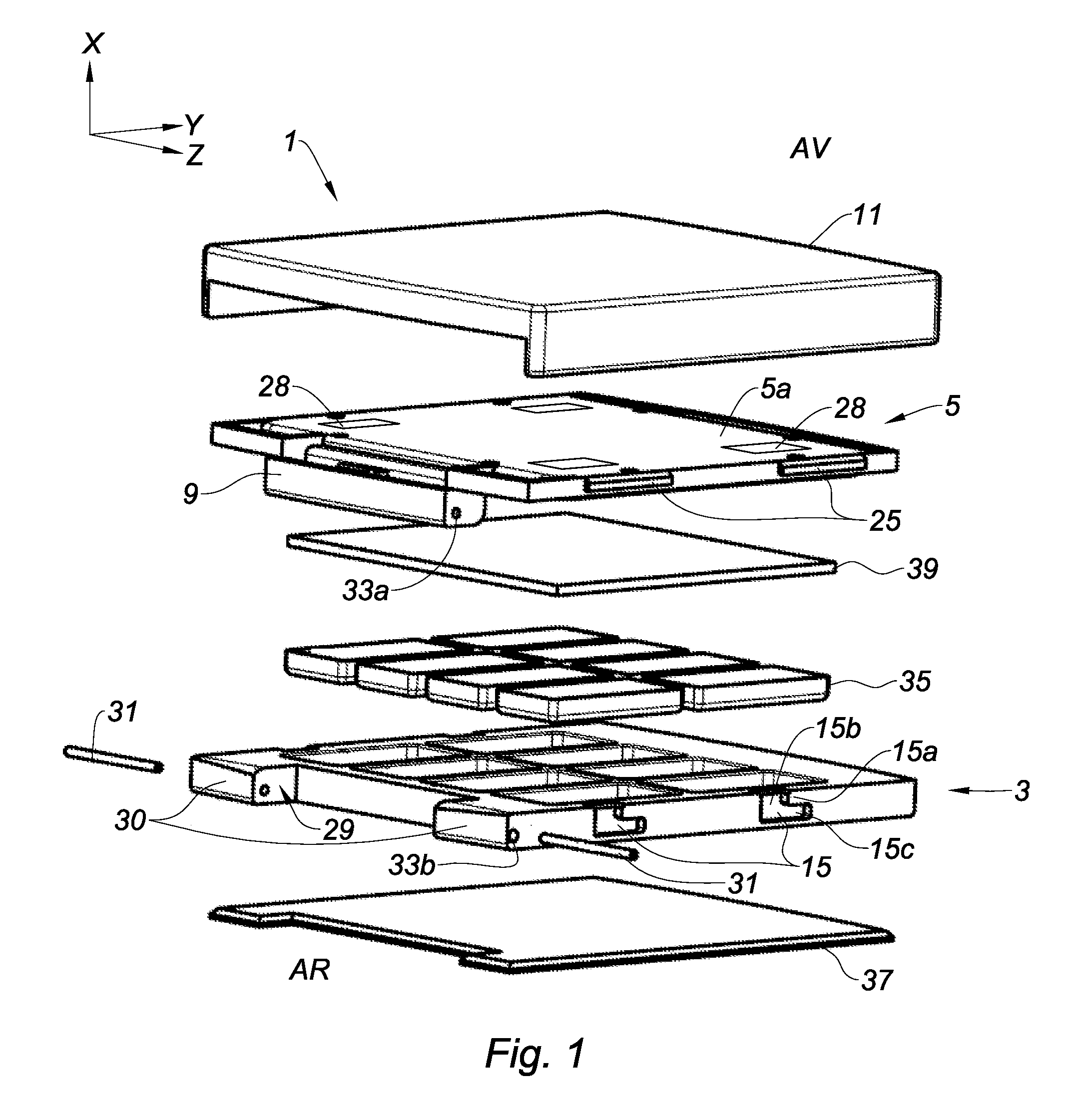
[0042] FIG. 1 is an exploded, perspective view of a first embodiment of a case for cosmetic products according to the invention;
[0043] FIG. 2 is a longitudinal cross-section view of the case illustrated in FIG. 1, in the closed position;
[0044] FIG. 3 is a longitudinal cross-section view of the case illustrated in FIG. 1, during opening;
[0045] FIG. 4 is a longitudinal cross-section view of the case illustrated in FIG. 1, in the open position;
[0046] FIG. 5a is a perspective view of the case in the open position illustrated in FIG. 4;
[0047] FIG. 5b is a front cross-section view of the case illustrated in FIG. 1, in the closed position;
[0048] FIG. 5c is a front view of the additional part of the case illustrated in FIG. 1 with a partial cross-section view in the lower part to make the inside visible;
[0049] FIG. 5d is a perspective view from above of the cover in FIG. 1;
[0050] FIG. 6 is an exploded, perspective view of a second embodiment of a case for cosmetic products according to the invention;
[0051] FIG. 7 is a perspective view of the case illustrated in FIG. 6, in the open position;
[0052] FIG. 8 is a longitudinal cross-section view of the case illustrated in FIG. 6, in the closed position;
[0053] FIG. 9 is a longitudinal cross-section view of the case illustrated in FIG. 6, during opening;
[0054] FIG. 10 is a longitudinal cross-section view of the case illustrated in FIG. 6, in the open position;
[0055] FIG. 11 is a view from below of the additional part of the case illustrated in FIG. 6;
[0056] FIG. 12 is a perspective view of the cover of the case illustrated in FIG. 6.
DETAILED DESCRIPTION OF THE INVENTION
[0057] The invention relates to a case 1 for cosmetic products including: [0058] a base 3, [0059] a cover 5, and [0060] a closing/opening means 7.
[0061] In the description which will follow, the trihedral X, Y, Z is referred to, represented in different figures. The axis X is the main direction of longitudinal extension of the case 1, referred to as main direction, the axis Z is an axis orthogonal to the axis X and parallel to the plane defined by a bottom of the case 1 and parallel to the axis of rotation of the cover 5 and finally the axis Y is an axis orthogonal to the axes X and Z.
[0062] In a non-limitative manner, the terms "higher" and "high" or "lower" and "low" are used in reference to the axis X.
[0063] The terms "interior" and "inner" are used with respect to the case 1 to name an element directed towards the centre of the case 1 or situated in the case 1 and the terms "exterior" and "outer" are used with respect to the case 1 to name an element directed towards the exterior of the case 1 or situated outside of the case 1.
[0064] The terms "front" and "rear" are used in reference to the axis Y.
[0065] The base 3 and the cover 5 are hinged with respect to one another via a pivot connection.
[0066] The case 1 is capable of occupying at least two separate positions: [0067] a closed position (that can be seen in FIGS. 2 and 8) wherein the cover 5 is held in position on the base 3 by the closing/opening means 7, and [0068] an open position (that can be seen in FIGS. 4, 5, 7 and 10) wherein the cover 5 is free to pivot with respect to the base 3.
[0069] The pivot connection is obtained by a part of the cover 5, referred to as hinging 9, enabling it to pivot with respect to the base 3 when the case 1 is in the open position.
[0070] The closing/opening means 7 includes: [0071] an additional part 11 which is in slide connection or in pivot connection with the cover 5, and [0072] one or more locking means 13 connected to the additional part 11--respectively from the base 3.
[0073] The locking means 13 are designed to each cooperate with a housing 15 provided in/on the base 3--respectively in/on the additional part 11. The plurality of locking means 13 form, with the housings 15, a multipoint locking.
[0074] Each instance of cooperation between one of the locking means 13 and the housing 15, which is connected to it, determines one of the locking points forming the multipoint locking.
[0075] Thus, the case 1 according to the invention has two main embodiments:
[0076] a first main embodiment represented in FIGS. 1 to 5d wherein the additional part 11 is in slide connection with the cover 5,
[0077] a second main embodiment represented in FIGS. 6 to 12 wherein the additional part 11 is in pivot connection with the cover 5.
[0078] Each one of the two main embodiments can have variants of embodiments.
[0079] Subsequently, some of these variants will be defined.
[0080] Moreover, the cosmetic case 1 includes a seal 21.
[0081] The seal 21 is provided on the surface of the base 3--respectively of the cover 5--so as to undergo flattening by the cover 5--respectively by the base 3--when the case 1 is in the closed position.
[0082] The multipoint locking is configured to apply sufficient pressure on the seal 21 when the case 1 is in the closed position such that the sealing against impurities and fluids between the inner and outer environments of the case 1, is total under the normal temperature and pressure conditions (NTPC), that is to say, a temperature of 0.degree. C. and a pressure of 1 atm.
[0083] "Impurities" mainly means solid impurities such as particles, dust, or cosmetic product powder.
[0084] "Fluid" means a liquid or a gas coming from the cosmetic product or from the exterior of the case. This can be, for example, a solvent, a volatile product, the cosmetic product itself, water, oxygen, etc.
[0085] The seal 21 can be returned to the surface of the base 3--conversely to the surface of the cover 5, held in position by surface gluing or over-molded with the base 3--conversely with the cover 5.
[0086] In certain variants, the seal 21 can be a means for assisting the opening of the case 1.
[0087] Advantageously, the seal 21 is made of elastomer, such as rubber, silicone, expanded polyethylene, such as Tresylene.RTM. or any other material enabling to guarantee the sealing of the case.
[0088] Advantageously, the actuation of the closing/opening means 7 is done by moving of the additional part 11 with respect to the cover 5, so as to engage/disengage the locking means 13 of their respective housing 15.
[0089] Thus, the passage from the open position to the closed position of the case 1, and conversely, can be done by applying a significant force if this is necessary. The presence of a seal 21 is therefore possible without impeding the engagement/disengagement of the locking means 13. In addition, this system does not provoke any friction on the seal 21.
[0090] Preferably, the additional part 11 is designed to make almost all of the cover 5 inaccessible to the touch of an exterior user when the case 1 is in the closed position, the hinging 9 being the only part of the cover 5 accessible to touch for an exterior user when the case 1 is in the closed position. In other words, the additional part 11 is designed so as to surround all of the cover 5, except for the hinging 9, which is what "almost all of the cover 5" means.
[0091] Thus, a case 1 is obtained wherein almost only the base 3 and the additional part 11 are accessible. This provides a refined and pleasant aesthetic appearance.
[0092] In addition, by preventing access from the cover 5 to the user in the closed position of the case 1, the user can easily move the additional part 11 with respect to the cover 5, without the movement being impeded by inadvertently holding the cover 5, for example.
[0093] This is particularly advantageous in the case of thin cases for which handling and moving only the additional part 11 can be difficult if the cover 5 is accessible.
[0094] In other words, the case 1 can be opened by pushing on both the upper surface and on the edge of the additional part 11, or on the layer thereof. Handling is thus easier and the movement is facilitated. The fingers of the user risk less sliding with respect to a system where the opening is achieved by sliding, by pressing only on the upper surface of a part.
[0095] Moreover, using an additional part 11 for the locking/unlocking of the case 1 and for placing this part 11 such that the cover 5 is almost inaccessible to the user enables to not obstruct the inner face of the cover 5 and to arrange a mirror there, for example.
[0096] Preferably, the locking points determined by the locking means 13 are evenly distributed over the inner circumference of the additional part 11--respectively over the periphery of the base 3--each being intended to cooperate with a dedicated housing 15.
[0097] The multipoint locking of the case 1 includes at least two locking points, preferably four locking points or more.
[0098] Advantageously, the number of locking points is an even number.
[0099] Preferably, the housings 15 are provided in the base 3 or the additional part 11 and are evenly distributed.
[0100] Each one of the housings 15 is, for example, a cavity, such as a notch, designed in the base 3 or the additional part 11 so as to retain the corresponding locking means 13 and holding the case 1 in the closed position.
[0101] The housings 15 can also be provided on the base 3 or the additional part 11. Each one of the housings 15 is thus, for example, in the form of an embossed zone configured to receive the corresponding locking means 13 and retaining it engaged to hold the case 1 in the closed position.
[0102] "Embossed" means a swelling, an element protruding from the base 3 or from the additional part 11, such as an embossed mold, a returned element (over-molded or glued) wherein a housing 15 is formed to receive the locking means 13.
[0103] The case 1 can also include a means for assisting the opening of the case 1. The assistance means can be presented in the form of at least one material beading (not represented) protruding from the base 3--respectively from the cover 5, in the direction of the cover 5--respectively of the base 3, close to the hinging 9.
[0104] The means for assisting the opening of the case 1 is intended to remove the cover 5 from the base 3 during the passage of the case 1 from the closed position to the open position, while maintaining a preopening of a few degrees, for example, a preopening of between 0.5 and 5.degree., preferably 3.degree..
[0105] Advantageously, the seal 21 can play the role of means for assisting the opening of the case 1.
[0106] In the first embodiment represented in FIGS. 1 to 5d, the case 1 is of parallelepiped shape, and more specifically, of square shape. It includes a rear side AR on which is positioned the pivot connection, a front side AV opposite the rear side AR and two lateral sides extending from the rear side AR towards the front side AV. A rectangular shape or any other shape, for example, mainly circular, could be considered.
[0107] In certain variants, the front side AV can include a gripping zone 22 that can be seen in FIG. 5c for example, so as to facilitate the opening of the cover 5.
[0108] In this first embodiment, the additional part 11 is in slide connection with the cover 5.
[0109] The slide connection between the additional part 11 and the cover 5 is ensured by the cooperation between the technical shapes present, on the one hand, over the outer periphery of the cover 5, and on the other hand, over an inner circumference of the additional part 11.
[0110] In this embodiment, each one of the lateral sides of the cover 5 includes two ridges 25 configured to cooperate with a groove 27 extending over the whole length of each one of the lateral sides of the additional part 11 (FIGS. 5b and 5c). In other words, the grooves 27 of the additional part 11 serve as slides to the ridges 25 of the cover 5, the additional part 11 being able to thus move in translation along the axis Y with respect to the cover 5.
[0111] Preferably, the locking means 13 are hooks.
[0112] This translation movement enables the actuation of the closing/opening means 7 and therefore engages/disengages the hooks 13 from their corresponding housing 15. To engage/disengage the hook 13 from the housing 15, the additional part moves in translation with respect to the base.
[0113] The cover 5 can also include at least one recess 28 so as to make the part of the cover 5 which supports the ridges 25 flexible (FIGS. 1 and 5d). This flexibility facilitates the assembly of the cover 5 in the additional part 11, in particular the assembly of the ridges 25 inside the grooves 27.
[0114] Preferably, the recess(es) 28 cross(es) and extend(s) over the part(s) of the cover 5 adjacent to the ridges 25.
[0115] In the variant of the embodiment represented in FIG. 5d, the cover includes four recesses 28. In other words, these recesses 28 give elasticity to the walls supporting the ridges 25 so as to facilitate the insertion, in particular by interlocking, preferably by clipping, of the part of the cover 5 inside the additional part 11.
[0116] In this embodiment, the hinging 9 is here situated on the rear side AR of the cover 5. It is a material extension, here in the form of a rectangular parallelepiped 9 being housed, during the assembly of the cover 5 to the base 3, in a housing 29 arranged behind the base 3 and formed between two extensions 30 of the base 3 situated towards the exterior of the case 1.
[0117] The material extension or hinging 9 is connected to the base 3 by the intermediary of at least one spindle 31 connecting the base 3 and the hinging 9 of the cover 5. Here, the hinging 9 includes two holes 33a situated on either side of the hinging 9 and the spindle corresponds to two pins 31.
[0118] Each one of the pins 31 has a first end inserted into one of the holes 33a of the hinging 9 and a second end inserted into a hole 33b formed on the rear side AR of the base 3 at the level of each one of the extensions 30. The pins 31 determine the axis of rotation of the cover 5, which is parallel to the axis Z. Any other means enabling to fulfil this function will be included in the invention.
[0119] In an embodiment not represented, it can also be devised that the only part of the cover 5 accessible to touch by an exterior user when the case 1 is in the closed position, referred to as hinging 9, is made of two material extensions of the cover 5 situated towards the exterior of the case 1 on the rear side AR and forming a housing wherein an extension of the base 3 is placed, for example, in the form of a rectangular parallelepiped, or a cylinder, each one of the extensions of the cover 5 and of the base 3 being bored to make at least one pin 31 pass through to make the pivot connection between the base 3 and the cover 5. In other words, it is a system opposite to the one represented here.
[0120] According to the invention, the case 1 includes a seal 21 provided, here, on the inner surface of the cover 5 so as to undergo flattening by the base 3 when the case 1 is in the closed position.
[0121] In this embodiment, the seal 21 is a material strand inserted into a groove 23 formed over the whole periphery of the inner surface of the cover 5 so as to obtain a sealing over the whole circumference of the case 1.
[0122] In this embodiment, the locking means are four hooks 13 distributed two-by-two over the lateral sides of the additional part 11 cooperating with four housings 15 distributed two-by-two over the lateral sides of the base 3.
[0123] The housings 15 are L-shaped and include an inlet 15b to enable the engagement of the corresponding hook 13 and a locking zone 15c to enable the locking of the hook after translation movement of the additional part 11.
[0124] Advantageously, the housings 15 have a protrusion 15a configured to form the locking zone 15c and to retain the hook 13 and hold the case 1 in the closed position (FIGS. 1, 3 and 5a).
[0125] In this embodiment, the hooks 13 are integrally formed with the additional part 11. Preferably, the hooks 13 are rigid to be able, in particular, to contain the pressure of the seal.
[0126] They can also have a technical form including a slope so as to amplify the closing force during the locking of the case 1 and to facilitate the entry of each one of the hooks 13 into the corresponding housing 15 during the passage from the open position to the closed position of the case 1 and the locking thereof. The term "rigid hook" means an element that resists to pressure, and that does not fold or deform under pressure.
[0127] In other variants of embodiments not represented, it can also be considered that the locking means 13 are connected to the base 3 and that the housings 15 are provided in the additional part 11.
[0128] It can also be considered that the housings 15 are designed on the base 3 or the additional part 11.
[0129] In this embodiment, the means for assisting the opening of the case 1 is the seal 21 provided on the surface of the cover 5. The seal is compressed when the case 1 is closed and it loosens when the locking means 13 are released, thus enabling a preopening of the case 1 by a few degrees, preferably 3.degree. (FIG. 3).
[0130] The opening mechanism will now be described in reference to FIGS. 2 to 4.
[0131] Initially, the user releases the hooks 13 from the additional part 11 inserted in their housing 15 provided on the base 3 by a translation movement along the axis Y of the additional part 11 with respect to the cover 5 and with respect to the base 3. In other words, in the closed position of the case 1, the hooks 13 are blocked at the level of the locking zone 15c from their housing 15 by the protrusion 15a.
[0132] During the translation movement of the additional part, the hooks 13 are located in the alignment of the inlet 15b, as can be seen in FIG. 3. Thus, nothing else retains the case in the closed position, the hooks 13 are thus released and the case 1 opens as can be seen in FIG. 3.
[0133] The opening of the cover 5 is particularly facilitated by the presence of the seal 21 which loosens and ensures a preopening of the case 1 by around 3.degree.. The user then finishes the opening of the case 1 by pivoting the cover 5 assembled to the additional part 11 until the open position illustrated in FIG. 4.
[0134] In the second embodiment represented in FIGS. 6 to 12, the cover 5, is of a circular shape and the additional part 11 has a mainly parallelepiped shape.
[0135] The case 1 has a rear part AR and a front part AV opposite the rear part AR. As for the first embodiment, a gripping zone (not represented) could be considered on the front part AV of the case 1.
[0136] Likewise, a circular shape could also be considered for the additional part 11.
[0137] In this second embodiment, the additional part 11 is in pivot connection with the cover 5.
[0138] As for the slide connection of the first embodiment, the pivot connection between the additional part 11 and the cover 5 is ensured by a cooperation of technical forms present, on the one hand, over the outer periphery of the cover 5, and on the other hand, over the inner circumference of the additional part 11.
[0139] In this embodiment, the inner circumference of the additional part 11 includes ridges 25, here three, evenly and angularly distributed and configured to cooperate with the grooves 27, here three, extending over the outer periphery of the cover 5 and evenly and angularly distributed (FIGS. 11 and 12).
[0140] The grooves 27 of the outer periphery of the cover 5 serve as a guiding path for the ridges 25 of the inner circumference of the additional part 11. The additional part 11 can thus be moved with respect to the cover 5 according to a rotation movement of axis parallel to the axis X. This rotation movement enables the actuation of the closing/opening means 7 and to engage/disengage the hook 13 from the housing 15.
[0141] The system enabling the pivot connection between the cover 5 and the base 3 is similar to that of the first embodiment.
[0142] The hinging 9 of the cover 5 is connected to the base 3 by means of two pins 31 inserted into the holes 33a, 33b of the hinging 9 and of the base 3. The pins 31 determine the axis of rotation of the cover 5, which is parallel to the axis Z.
[0143] In this second embodiment, the case 1 also includes a seal 21 provided on the inner surface of the cover 5 so as to undergo flattening by the base 3 when the case 1 is in the closed position.
[0144] Preferably, the seal 21 is in the form of a material strand inserted into a groove 23 formed over the whole periphery of the inner surface of the cover so as to obtain a sealing over the whole circumference of the case 1.
[0145] In this embodiment, the locking means are also four hooks 13. The hooks 13 are integrally formed with the base 3 and are regularly angularly distributed over it. The hooks 13 cooperate with four housings 15 regularly angularly distributed in the additional part 11.
[0146] Preferably, the hooks 13 are rigid and have a technical form including a slope so as to be able to contain the pressure of the seal 21 and amplify the closing force during the locking of the case 1.
[0147] In this embodiment, the cover 5 advantageously includes four slots 24 evenly and angularly distributed to enable the passage of the hooks 13 to their corresponding housing 15 provided in the additional part 11, and/or the releasing of the hooks 13 from their housing 15.
[0148] After rotation of the additional part 11 with respect to the cover 5, the hooks 13 are blocked by the cover 5 and the case 1 is held in the closed position.
[0149] As in the first embodiment, the means for assisting the opening of the case 1 is, here, the seal 21 provided on the surface of the cover 5. The seal 21 is compressed when the case 1 is closed and it loosens when the locking means 13 are released, thus enabling a preopening of the case 1 by a few degrees, preferably 3.degree. (FIG. 9).
[0150] The opening mechanism will now be defined in reference to FIGS. 8 to 10.
[0151] The opening mechanism is similar to that of the first embodiment, only the type of movement of the additional part 11 with respect to the cover 5 differs. Indeed, in the first embodiment, the movement is a translation movement along the axis Y whereas in this second embodiment, the additional part 11 makes a rotation movement with respect to the cover 5.
[0152] Initially, the user releases the hooks 13 from the base 3 inserted in their corresponding housing 15 provided on the additional part 11 by a rotation movement of axis parallel to the axis X of the additional part 11 with respect to the cover 5 and with respect to the base 3.
[0153] In the closed position of the case 1, the hooks 13 are held in the housings 15 by the cover 5 which replaces the protrusion 15a from the first embodiment. After rotation of the additional part 11, the hooks 13 are located aligned with the slots 24 of the cover 5 and can thus be released. The case 1 can open as can be seen in FIG. 9.
[0154] The opening of the cover 5 is particularly facilitated by the presence of the seal 21 which loosens and ensures a preopening of the case 1 by around 3.degree.. The user can finish the opening of the case 1 by pivoting the cover 5 assembled to the additional part 11 to the open position illustrated in FIG. 10.
[0155] Advantageously, as represented in the different embodiment variants of the two embodiments, the base 3 is intended to receive a cosmetic product and/or a cosmetic product applicator, for example by the intermediary of at least one cup 35. Advantageously, the cosmetic product includes a volatile and/or damp composition.
[0156] The base 3 can also include a separate bottom 37 as can be seen in FIGS. 1 and 6. The bottom 37 is attached to the base 3 by any suitable means, for example, by interlocking, clipping, screwing, welding or gluing. A separate bottom facilitates, in particular, the production of the base 3 by molding, in particular in the case of plastic cases.
[0157] Advantageously, the cover 5 is capable of receiving a mirror 39 of the pocket mirror type. The mirror 39 is attached to the cover 5, in particular on the inner surface of the cover 5, by any suitable means, for example by interlocking, clipping, screwing or gluing. Users can thus apply make-up wherever they are, by looking in the mirror 29. Thanks to the specific opening/closing system of the case 1, the cover 5 can easily include a mirror 29 on the inner face thereof.
[0158] Advantageously, the different parts are made of thermoplastic materials, for example, polypropylene (PP), polyethylene (PE), polyoxymethylene (POM), polybutylene terephthalate (PBT), acrylonitrile butadiene styrene (ABS), styrene acrylonitrile (SAN), styrene acrylonitrile/acrylonitrile butadiene styrene (SAN/ABS) or polycarbonate/acrylonitrile butadiene styrene (PC/ABS), preferably ABS, SAN/ABS or PC/ABS which are materials that have a more aesthetic finish.
[0159] To obtain additional advantageous effects, the variants and the embodiments can be combined without moving away from the scope of the invention.
[0160] In the cosmetic case 1 according to the invention, the seal 21 is arranged on the base or the cover and ensures a sealing of the case. The sealing is improved by the presence of a multipoint locking. Thus, the locking means 13 are distributed over the circumference of the case 1 and ensure sufficient pressure on the seal 21 to maintain a sealing, not only against impurities but also against fluids, such as liquids, between the interior and the exterior of the case.
[0161] In addition, the case 1 includes an additional part 11 which can be moved with respect to the cover 5. This enables the passage from the closed position to the open position of the case 1 by applying a more significant force, thus a seal 21 can be arranged between the cover 5 and the base 3 without complicating the opening or closing.
[0162] In addition, the additional part 11 enables to avoid possible friction between the seal 21 and the cover 5 and in particular, premature wear of the seal and damaging the sealing of the case 1.
[0163] Moreover, the conventional locking, in particular by pushbutton, is replaced by a differential force system. The user activates the locking manually and thus the pushbutton system can be avoided.
[0164] More freedom in the design of the case is possible. A very thin cosmetic case 1 can thus be considered, with a very refined design, without any visible locking/unlocking element.
[0165] Also, it can be provided to integrate the additional elements at the level of the cover 5, such as a mirror, given that the opening is triggered by moving an additional part 11 surrounding the cover 5 and that the cover 5 is not obstructed by a possible pushbutton. The present invention may be embodied within a system, a method, a computer program product or any combination thereof. The computer program product may include a computer readable storage medium or media having computer readable program instructions thereon for causing a processor to carry out aspects of the present invention. The computer readable storage medium can be a tangible device that can retain and store instructions for use by an instruction execution device. The computer readable storage medium may be, for example, but is not limited to, an electronic storage device, a magnetic storage device, an optical storage device, an electromagnetic storage device, a semiconductor storage device, or any suitable combination of the foregoing.
[0166] The terminology used herein is for the purpose of describing particular embodiments only and is not intended to be limiting of the invention. As used herein, the singular forms "a", "an" and "the" are intended to include the plural forms as well, unless the context clearly indicates otherwise. It will be further understood that the terms "includes" and/or "including," when used in this specification, specify the presence of stated features, steps, elements, and/or components, but do not preclude the presence or addition of one or more other features, steps, elements, components, and/or groups thereof.
[0167] The corresponding structures, materials, acts, and equivalents of all means or step plus function elements in the claims below are intended to include any structure, material, or act for performing the function in combination with other claimed elements as specifically claimed. The description of the present invention has been presented for purposes of illustration and description, but is not intended to be exhaustive or limited to the invention in the form disclosed. Many modifications and variations will be apparent to those of ordinary skill in the art without departing from the scope and spirit of the invention. The embodiment was chosen and described in order to best explain the principles of the invention and the practical application, and to enable others of ordinary skill in the art to understand the invention for various embodiments with various modifications as are suited to the particular use contemplated.
[0168] Having thus described the invention of the present application in detail and by reference to embodiments thereof, it will be apparent that modifications and variations are possible without departing from the scope of the invention defined in the appended claims as follows:
* * * * *
D00000
D00001
D00002
D00003
D00004
D00005
XML
uspto.report is an independent third-party trademark research tool that is not affiliated, endorsed, or sponsored by the United States Patent and Trademark Office (USPTO) or any other governmental organization. The information provided by uspto.report is based on publicly available data at the time of writing and is intended for informational purposes only.
While we strive to provide accurate and up-to-date information, we do not guarantee the accuracy, completeness, reliability, or suitability of the information displayed on this site. The use of this site is at your own risk. Any reliance you place on such information is therefore strictly at your own risk.
All official trademark data, including owner information, should be verified by visiting the official USPTO website at www.uspto.gov. This site is not intended to replace professional legal advice and should not be used as a substitute for consulting with a legal professional who is knowledgeable about trademark law.