Unique Twelve-different-application Umbrella System, Having Pivotable Pole Receiver Systems, Rotatable Pole-receiver-locking Adjustor System, Curved-surface Adaptor Systems, Trailer-hitch Adaptor System, And Spiral-shovel Spike System
Volin; Dee
U.S. patent application number 16/033877 was filed with the patent office on 2019-01-31 for unique twelve-different-application umbrella system, having pivotable pole receiver systems, rotatable pole-receiver-locking adjustor system, curved-surface adaptor systems, trailer-hitch adaptor system, and spiral-shovel spike system. The applicant listed for this patent is Dee Volin. Invention is credited to Dee Volin.
| Application Number | 20190029216 16/033877 |
| Document ID | / |
| Family ID | 65137845 |
| Filed Date | 2019-01-31 |


View All Diagrams
| United States Patent Application | 20190029216 |
| Kind Code | A1 |
| Volin; Dee | January 31, 2019 |
UNIQUE TWELVE-DIFFERENT-APPLICATION UMBRELLA SYSTEM, HAVING PIVOTABLE POLE RECEIVER SYSTEMS, ROTATABLE POLE-RECEIVER-LOCKING ADJUSTOR SYSTEM, CURVED-SURFACE ADAPTOR SYSTEMS, TRAILER-HITCH ADAPTOR SYSTEM, AND SPIRAL-SHOVEL SPIKE SYSTEM
Abstract
A multi-pet locking-head-and-locking-tail-push-rod pet crate comprises: a handle bridge, a handle channel molded inside the handle bridge for containing grooming tools, handle clasps respectively molded in the handle bridge for fastening poop bags thereto, a top panel, a bottom panel, a left panel, a right panel, a front panel, a rear panel, at least one divider, panel-locking hooks and clamps for hooking and clamping the panels together, a slanted tray for draining urine, urine-storing gutters and ridges molded around the tray for supporting pet paws and for keeping pets away from urine, top and bottom low-friction rails welded to the front panel, multi-position door-glider-locking recesses formed in the bottom low-friction rail for locking the auto-indexing multi-position door gliders and for adjusting horizontal or slanted and stationary or moving positions of the auto-indexing multi-position doors, first and second auto-indexing multi-position doors inserted between the top and bottom low-friction rails, first and second auto-indexing multi-position door gliders respectively cast to the first and second doors for horizontally or slantedly being locked in the multi-position door-glider-locking recesses to horizontally or slantedly lock said first and the second doors in multiple horizontal or slanted and stationary or moving positions, first and second push-rods respectively and movably attached to the first and second doors, first and second door-locking push-rod heads respectively cast to the first and second push-rods for locking the first and second doors together, and first and second multi-position door-locking push-rod tails respectively cast to the first and second push-rods for locking and aligning the first and second doors to the front panel and for adjusting multiple positions of the first and second doors.
| Inventors: | Volin; Dee; (Fairview, OR) | ||||||||||
| Applicant: |
|
||||||||||
|---|---|---|---|---|---|---|---|---|---|---|---|
| Family ID: | 65137845 | ||||||||||
| Appl. No.: | 16/033877 | ||||||||||
| Filed: | July 12, 2018 |
Related U.S. Patent Documents
| Application Number | Filing Date | Patent Number | ||
|---|---|---|---|---|
| 62536471 | Jul 25, 2017 | |||
| Current U.S. Class: | 1/1 |
| Current CPC Class: | A01K 1/0005 20130101; A01K 13/00 20130101; A01K 1/034 20130101; A01K 1/0114 20130101; A01K 1/029 20130101; A01K 1/0107 20130101; A01K 1/0245 20130101; A01K 1/0017 20130101 |
| International Class: | A01K 1/02 20060101 A01K001/02; A01K 13/00 20060101 A01K013/00; A01K 1/00 20060101 A01K001/00; A01K 1/01 20060101 A01K001/01 |
Claims
1. A multi-position-double-locking-head-and-locking-tail-push-rod pet crate comprising: a handle bridge; a plurality of handle stabilizers, said handle bridge molded to said handle stabilizers; a multi-grooming-tool-clamping handle channel molded inside said handle bridge for insertably containing a plurality of grooming tools and for being used as a hook or as a clamp; a plurality of poop-bag-clamping handle clasps respectively molded in said handle stabilizers for securely fastening poop bags to said handle bridge and for being used as hooks; a plurality of handle hooks, said handle stabilizers respectively molded to said handle hooks; top, bottom, left, right, front, and rear panels, said handle hooks respectively hooked on said top panel; a plurality of panel-locking hooks respectively hooked on said top, said left, said right, said front, and said rear panels; a panel-folding clamp clamped on said top, said bottom, said left, said right, said front, and said rear panels; a plurality of panel-coupling clamps respectively clamped on said top, said bottom, said left, said right, said front, and said rear panels; at least one movable crate divider respectively disposed inside said top, said bottom, said left, said right, said front, and said rear panels for creating multiple pet-containing compartments; a slanted urine-storing tray disposed on said bottom panel for conveniently keeping pets away and not on urine; a plurality of urine-storing gutters respectively molded around said slanted urine-storing-gutter tray for storing urine run-off from said slanted urine-storing-gutter tray and for conveniently keeping pets away and not on urine; a plurality of gutter ridges respectively molded inside said urine-storing gutters for supporting pet paws while stepping upon and for conveniently keeping pets away and not on urine; a top low-friction rail welded to said front panel; a bottom low-friction rail welded to said front panel; a plurality of multi-position door-corner-glider-locking recesses respectively formed in said bottom low-friction rail; a plurality of door extracting-inserting slots respectively formed in said top low-friction rail; first and second auto-indexing multi-position doors conveniently inserted through said door extracting-inserting slots, and respectively and slidably inserted between said top low-friction rail and said bottom low-friction rail; first and second auto-indexing multi-position door-corner-gliders respectively cast to said first and said second auto-indexing multi-position doors for horizontally or slantedly being locked in said multi-position door-corner-glider-locking recesses to horizontally or slantedly lock said first and said second auto-indexing multi-position doors in a plurality of horizontal or slanted and stationary or moving positions, and for precisely or conveniently adjusting a plurality of horizontal or slanted and stationary or moving positions of said first and said second auto-indexing multi-position doors; first and second push-rod hinges respectively welded to said first and said second auto-indexing multi-position doors; first and second push-rod levers respectively welded to said first and said second push-rod hinges; first and second push-rods respectively and rotatably attached to said first and said second push-rod hinges; first and second door-locking push-rod heads respectively cast to said first and said second push-rods; first and second push-rod-head-locking rings respectively welded to said first and said second auto-indexing multi-position doors; first and second multi-position door-locking push-rod tails respectively cast to said first and said second push-rods for horizontally or slantedly locking and aligning said first and said second auto-indexing multi-position doors to said front panel to horizontally or slantedly lock said first and said second auto-indexing multi-position doors in a plurality of horizontal or slanted and stationary or moving positions, and for precisely or conveniently adjusting a plurality of horizontal or slanted and stationary or moving positions of said first and said second auto-indexing multi-position doors; first and second multi-position push-rod-tail-locking wires respectively welded to said front panel for providing a plurality of locations to which to horizontally or slantedly lock said first and said second multi-position door-locking push-rod tails to provide a plurality of horizontal or slanted locking locations for said first and said second auto-indexing multi-position doors.
2. The multi-position-double-locking-head-and-locking-tail-push-rod pet crate of claim 1, further comprising a plurality of slot-screw holes, a plurality of door-blocking slot screws, a central doorstop, and at least one divider, wherein said slot-screw holes respectively are drilled in said top low-friction rail for receiving said door-blocking slot screws therethrough, said door-blocking slot screws respectively are screwed into said slot-screw holes for preventing said first and said second auto-indexing multi-position doors from vertical extraction through said door extracting-inserting slots, said central doorstop is welded to said bottom low-friction rail for preventing further movement of said first and said second auto-indexing multi-position doors, said at least one divider is respectively disposed inside said top, said bottom, said left, said right, said front, and said rear panels for creating multiple pet-containing compartments.
3. The multi-position-double-locking-head-and-locking-tail-push-rod pet crate of claim 1, wherein said top low-friction rail has a plurality of top low-friction rail arcs cast therein and said bottom low-friction rail has a plurality of bottom low-friction rail arcs cast therein, wherein said top low-friction rail arcs and said bottom low-friction rail arcs each have a C shape for reducing contact and thereby lowering friction between said top low-friction rail, said bottom low-friction rail, said first auto-indexing multi-position door, and said second auto-indexing multi-position door.
4. The multi-position-double-locking-head-and-locking-tail-push-rod pet crate of claim 1, wherein said top low-friction rail and said bottom low-friction rail each are formed into an I shape with a U-shaped cross-section.
5. The multi-position-double-locking-head-and-locking-tail-push-rod pet crate of claim 1, wherein said multi-position door-corner-glider-locking recesses each are formed into a cup shape, and said first and second auto-indexing multi-position door-corner-gliders each are formed into a U shape.
6. The multi-position-double-locking-head-and-locking-tail-push-rod pet crate of claim 1, wherein said handle bridge is made of plastic material, said handle stabilizers each are made of plastic material.
7. The multi-position-double-locking-head-and-locking-tail-push-rod pet crate of claim 1, wherein said top low-friction rail is made of metallic material, said bottom low-friction rail is made of metallic material.
8. The multi-position-double-locking-head-and-locking-tail-push-rod pet crate of claim 1, wherein said first and said second auto-indexing multi-position doors each are made of metallic material.
9. The multi-position-double-locking-head-and-locking-tail-push-rod pet crate of claim 1, wherein said multi-position-double-locking-head-and-locking-tail-push-rod pet crate is made of plastic material, metallic material, or plastic and metallic materials.
10. A multi-position-double-locking-head-and-locking-tail-push-rod pet crate comprising: a handle bridge; a plurality of handle stabilizers, said handle bridge molded to said handle stabilizers; a multi-grooming-tool-clamping handle channel molded inside said handle bridge; a plurality of poop-bag-clamping handle clasps respectively molded in said handle stabilizers; a plurality of handle hooks, said handle stabilizers respectively molded to said handle hooks; top, bottom, left, right, front, and rear panels, said handle hooks respectively hooked on said top panel; a plurality of panel-locking hooks respectively hooked on said top, said left, said right, said front, and said rear panels; a panel-folding clamp clamped on said top, said bottom, said left, said right, said front, and said rear panels; a plurality of panel-coupling clamps respectively clamped on said top, said bottom, said left, said right, said front, and said rear panels; a urine-storing tray disposed on said bottom panel for conveniently keeping pets away and not on urine; a top low-friction rail welded to said front panel; a bottom low-friction rail welded to said front panel; a plurality of multi-position door-corner-glider-locking recesses respectively formed in said bottom low-friction rail; first and second multi-position doors respectively and slidably inserted between said top low-friction rail and said bottom low-friction rail; first and second multi-position door-corner-gliders respectively cast to said first and said second multi-position doors for horizontally or slantedly being locked in said multi-position door-corner-glider-locking recesses to horizontally or slantedly lock said first and said second multi-position doors in a plurality of horizontal or slanted and stationary or moving positions, and for precisely or conveniently adjusting a plurality of horizontal or slanted and stationary or moving positions of said first and said second multi-position doors; first and second push-rod hinges respectively welded to said first and said second multi-position doors; first and second push-rod levers respectively welded to said first and said second push-rod hinges; first and second push-rods respectively and rotatably attached to said first and said second push-rod hinges; first and second door-locking push-rod heads respectively cast to said first and said second push-rods; first and second push-rod-head-locking rings respectively welded to said first and said second multi-position doors; first and second multi-position door-locking push-rod tails respectively cast to said first and said second push-rods for horizontally or slantedly locking and aligning said first and said second multi-position doors to said front panel to horizontally or slantedly lock said first and said second multi-position doors in a plurality of horizontal or slanted and stationary or moving positions, and for precisely or conveniently adjusting a plurality of horizontal or slanted and stationary or moving positions of said first and said second multi-position doors; first and second multi-position push-rod-tail-locking wires respectively welded to said front panel for providing a plurality of locations to which to horizontally or slantedly lock said first and said second multi-position door-locking push-rod tails to provide a plurality of horizontal or slanted locking locations for said first and said second multi-position doors.
11. The multi-position-double-locking-head-and-locking-tail-push-rod pet crate of claim 10, further comprising a central doorstop and at least one divider, wherein said central doorstop is welded to said bottom low-friction rail for preventing further movement of said first and said second multi-position doors, said at least one divider is respectively disposed inside said top, said bottom, said left, said right, said front, and said rear panels for creating multiple pet-containing compartments.
12. The multi-position-double-locking-head-and-locking-tail-push-rod pet crate of claim 10, wherein said top low-friction rail has a plurality of top low-friction rail arcs cast therein and said bottom low-friction rail has a plurality of bottom low-friction rail arcs cast therein, wherein said top low-friction rail arcs and said bottom low-friction rail arcs each have a C shape for reducing contact and thereby lowering friction between said top low-friction rail, said bottom low-friction rail, said first multi-position door, and said second multi-position door.
13. The multi-position-double-locking-head-and-locking-tail-push-rod pet crate of claim 10, wherein said top low-friction rail and said bottom low-friction rail each are formed into an I shape with a U-shaped cross-section.
14. The multi-position-double-locking-head-and-locking-tail-push-rod pet crate of claim 10, wherein said multi-position door-corner-glider-locking recesses each are formed into a cup shape, and said first and second multi-position door-corner-gliders each are formed into a U shape.
15. The multi-position-double-locking-head-and-locking-tail-push-rod pet crate of claim 10, wherein said handle bridge is made of plastic material, said handle stabilizers each are made of plastic material.
16. The multi-position-double-locking-head-and-locking-tail-push-rod pet crate of claim 10, wherein said top low-friction rail is made of metallic material, said bottom low-friction rail is made of metallic material.
17. The multi-position-double-locking-head-and-locking-tail-push-rod pet crate of claim 10, wherein said first and said second multi-position doors each are made of metallic material.
18. The multi-position-double-locking-head-and-locking-tail-push-rod pet crate of claim 10, wherein said multi-position-double-locking-head-and-locking-tail-push-rod pet crate is made of plastic material, metallic material, or plastic and metallic materials.
19. A multi-position-double-locking-head-and-locking-tail-push-rod pet crate, comprising: a handle bridge; a plurality of handle stabilizers, said handle bridge molded to said handle stabilizers; a plurality of handle hooks, said handle stabilizers respectively molded to said handle hooks; top, bottom, left, right, front, and rear panels, said handle hooks respectively hooked on said top panel; a plurality of panel-locking hooks respectively hooked on said top, said left, said right, said front, and said rear panels; a panel-folding clamp clamped on said top, said bottom, said left, said right, said front, and said rear panels; a plurality of panel-coupling clamps respectively clamped on said top, said bottom, said left, said right, said front, and said rear panels; a urine-storing tray disposed on said bottom panel; a top low-friction rail welded to said front panel; a bottom low-friction rail welded to said front panel; first and second multi-position doors respectively and slidably inserted between said top low-friction rail and said bottom low-friction rail; first and second multi-position door-corner-gliders respectively cast to said first and said second multi-position doors; first and second push-rod hinges respectively welded to said first and said second multi-position doors; first and second push-rod levers respectively welded to said first and said second push-rod hinges; first and second push-rods respectively and rotatably attached to said first and said second push-rod hinges; first and second door-locking push-rod heads respectively cast to said first and said second push-rods; first and second push-rod-head-locking rings respectively welded to said first and said second multi-position doors; first and second multi-position door-locking push-rod tails respectively cast to said first and said second push-rods for horizontally or slantedly locking and aligning said first and said second multi-position doors to said front panel to horizontally or slantedly lock said first and said second multi-position doors in a plurality of horizontal or slanted and stationary or moving positions, and for precisely or conveniently adjusting a plurality of horizontal or slanted and stationary or moving positions of said first and said second multi-position doors.
20. The multi-position-double-locking-head-and-locking-tail-push-rod pet crate of claim 10, further comprising a central doorstop and at least one divider, wherein said central doorstop is welded to said bottom low-friction rail for preventing further movement of said first and said second multi-position doors, said at least one divider is respectively disposed inside said top, said bottom, said left, said right, said front, and said rear panels for creating multiple pet-containing compartments.
Description
1. FIELD OF THE INVENTION
[0001] The present invention relates to a pet crate, which is cheap to produce, is easy to ship as one unit, requires little assembly, and can be quickly and easily be unfolded. Particularly, the present invention relates to a multi-pet locking-head-and-locking-tail-push-rod pet crate, comprising: [0002] 1) Grooming-tool-poop-bag handle system, [0003] 2) Low-friction door-rail system, [0004] 3) Quick-assembly door system, and [0005] 4) Multi-position-double-locking-head-and-locking-tail multi-position-double-push-rod multi-position-double-door system.
2. DESCRIPTION OF THE PRIOR ART
[0006] A number of pet crates have been introduced.
[0007] U.S. Pat. No. 4,023,698, issued 1977 May 17, to Raymond Joseph, relates to a container, such as a tote box or pallet heightening container comprising an opening in one of its side walls, and at least one movable shutter for closing said opening. The shutter is hingedly mounted at its bottom edge by means of elongated rings to the bottom edge of the opening or of the next underlying shutter, if any. Side lock bolts are rigidly secured to the upper portion of each shutter and adapted to engage through notches a U-sectioned lateral slideway running along the lateral edges of the opening. Detent means are provided for holding the shutter in its open position.
[0008] U.S. Pat. No. 4,762,085, issued 1988 Aug. 9, to Vladimir J. Ondrasik, relates to a collapsible wire cage having opposite side walls, upper and lower walls, and end walls of wire grille construction defining an enclosure. Each end wall is pivoted at one side edge to a respective one of the side walls and has a releasable locking mechanism at its other side edge for releasably securing it to the other side wall. The upper and lower walls are each formed in two panel sections, one of which is pivoted to one of the side walls and the other of which is pivoted to the other side wall. The panel sections are pivotally connected together to allow them to pivot between an expanded position in which they are coplanar and a folded position in which they are pivoted inwardly and flattened against one another to collapse the cage. A releasable locking mechanism is provided on each of the collapsible walls to retain them in their expanded, coplanar position. In an alternative, the side walls may be collapsible with the end walls pivotally secured to the upper and lower walls.
[0009] U.S. Pat. No. 4,763,606, issued 1988 Aug. 16, to Vladimir J. Ondrasik, describes an animal cage comprising an outer frame defining the peripheral edges of a box like enclosure, and a series of wall panels for releasably mounting in respective faces of the enclosure to form spaced side, end, and top and bottom walls of the enclosure. Each panel is held in the surrounding frame by spring loaded latch pins adjacent each end of the frame which are urged into corresponding openings in the frame and can be released at either end for swinging the panel open about the opposite end latch pin, or released at both ends for removing the panel from the frame. The frame is releasably securable to one or more additional frames arranged one on top of the other, side to side, or end to end. The internal wall panels may be removed to increase the height, width or length of the enclosure, or left in place to provide an assembly of separate cages for different animals
[0010] U.S. Pat. No. 5,233,939, issued 1997 Dec. 30, to Arthur J. Randolph, describes an animal cage comprising an outer frame defining the peripheral edges of a box like enclosure, and a series of wall panels for releasably mounting in respective faces of the enclosure to form spaced side, end, and top and bottom walls of the enclosure. Each panel is held in the surrounding frame by spring loaded latch pins adjacent each end of the frame which are urged into corresponding openings in the frame and can be released at either end for swinging the panel open about the opposite end latch pin, or released at both ends for removing the panel from the frame. The frame is releasably securable to one or more additional frames arranged one on top of the other, side to side, or end to end. The internal wall panels may be removed to increase the height, width or length of the enclosure, or left in place to provide an assembly of separate cages for different animals.
[0011] U.S. Pat. No. 5,373,810, issued 1994 Dec. 20, to Edwin R. Martin, discloses a combination cage locking and latching device made from a light gauge wire or molded plastic which is rotatably fixed to the cage door top horizontal wire. The device consists of shaped wire having a locking portion, a latching portion, and a "U"-shaped mounting portion formed between the locking portion and the latching portion at a position nearer to the locking portion. The locking portion is formed sufficiently long to extend below and to engage a first horizontal rod to prevent unauthorized opening, and the latching portion is formed and positioned to extend outside the cage for grasping and pulling the cage door upwardly to an open position and sufficiently long for engaging a second horizontal rod of said cage for holding the cage door in an open position.
[0012] U.S. Pat. No. 6,192,834, issued 2003 Jan. 7, to Kevin Kolozsvari, describes a collapsible cage for housing an animal having an expanded and a collapsed configuration. The collapsible cage comprises a top platform and a bottom platform defining the ceiling and floor of said collapsible cage, a first accordion wall, a second accordion wall, a first end wall, and a second end wall, which collectively define a cage interior when the collapsible cage is in an expanded configuration. The first end wall rotatably engages the bottom platform and the second end wall rotatably engages the top platform. During the transition of the collapsible cage from the expanded configuration to the collapsed configuration, the first and second end walls and the first and second accordion walls pivot into the cage interior and the top platform approaches the bottom platform.
[0013] U.S. Pat. No. 6,681,720, issued 2004 Jan. 28, to Scott A. Skurdalsvold, relates to a wire cage which is operable between an expanded position and a folded position which includes a top wall and a bottom wall, a first sidewall, a second sidewall, a front wall and a rear wall attach to the bottom and top walls. The front and rear walls contain rounded sides. The cage includes an entrance door. A pass through door is mounted on the entrance door. In order to open the pass through door, the entrance door must be closed and locked. The cage top wall optionally contains a top wall door hinged on the edge of the top wall so that the user can easily access the cage from the top wall. The top door can be rotated so that it rests flush with the cage sidewall. A pan is inserted over the bottom surface.
[0014] U.S. Pat. No. 6,691,463, issued 2004 Feb. 17, to Robert A. Richmond, relates to a kennel door apparatus for selectively "opening" and "closing" a kennel door, the kennel door is sized to cover an opening located in a kennel wall between a kennel pen and a common kennel area for selective access thereto. A door opening attachment may be used to cover the opening in the kennel wall. The kennel door apparatus is adapted for horizontal and vertical sliding door actuation. First and second opposing channel guides are secured to opposing sides of a protective panel. A sliding door is slidably received between the wall confronting side and the panel side of the opposing channel guides.
[0015] U.S. Pat. No. 6,883,463, issued 2005 Apr. 26, to David B. Link, relates to an animal enclosure, having a top wall panel, a bottom rack disposed opposite to the top wall panel, two opposite first side wall panels, a third side wall panel and a fourth side wall panel. Each of the first side wall panels has a top edge hinged to the top wall panels and a bottom edge hinged with the bottom rack at a first elevation. The second side wall panel disposed between and adjacent to the first side wall panels has a bottom edge hinged to the bottom rack at a second elevation. The third side wall panel is opposite to the second side wall panel and adjacent to the first side wall panels. The third side wall has a bottom edge hinged to the bottom rack at a third elevation. The first, second and third elevations are at different from each other such that the top wall panel, the first, second and fourth side wall panels can be folded stacked with each other on the bottom rack.
[0016] U.S. Pat. No. 7,213,368, issued 2007 May 8, to Mogens Eliasen, relates to a canopy with an automatic roof structure having improved structural stability. The canopy comprises a plurality of vertical support posts connected by trusses. A plurality of roof support rods extend from the vertical support posts to a central hub. At least one of the roof support rods has a cantilever support extending from the associated slide or thereabouts to a pivot on the roof support rod. The canopy also comprises central truss supports and stubs extending from the connection of the lateral trusses to the central hub. The canopy has an expanded, open configuration and a collapsed, closed configuration.
[0017] U.S. Pat. No. 7,918,188, issued 2011 Apr. 5, to Mike Harper, outlines a cage for housing an animal comprising a top wall, bottom, first and second sidewalls, a front wall and a rear wall. A door is disposed in at least one of the walls and is hinged for movement between an open and closed position. The door is mounted in a wall having a doorway. The door includes a plurality of loops on each side of the door. The wall includes a plurality of loops along each side of the doorway. The door loops are positionable adjacent the wall loops when the door is disposed within the doorway to form mating hinge structures. A hinge pin is selectively insertable into either of the door loops on one edge of the door together with the corresponding loops on the wall, to thereby hingedly mount the door to the wall for door swinging movement in either a first direction or a second direction with respect to the wall.
[0018] U.S. Pat. No. 8,127,719, issued 2012 Mar. 6, to Todd M. Jakubowski, outlines a pet crate is having a blow molded polymeric base along with side, front and top panels made with strong, lightweight polymeric frame members and grates. The grates are used in the front, back and side panels to provide strength as well as a large open mesh area for better visibility and pet comfort. The mesh preferably is provided as hinged access panels at least on the sides. The front and top of the crate are also openable for access to the pet crate. The pet crate is collapsible to a folded, flat condition by unlatching the front panel and stowing it along the inside of the top panel and releasing latches between the top and back panels and the side panels. The side panels, back panel and top panel can then be collapsed inwardly onto one another to form a generally flat, stowed configuration for the pet crate.
[0019] U.S. Pat. No. 8,141,517, issued 2012 Mar. 27, to Naoki Shimoda, refers to a pet pen comprising a plurality of enclosing members with each enclosing member having a wall body and an opening end. The enclosing members form the pen by overlapping a portion of the wall body at two or more of the opening ends, and the pen width can be adjusted by adjusting the length of the overlapping portion. The pen width can be adjusted without removing an enclosing member.
[0020] U.S. Pat. No. 8,210,127, issued 2012 Jul. 3, to Daisuke Kaneda, refers to a pet restriction device comprising an entry panel, at least one door located on the entry panel and comprising a door axis, and a locking device. The locking device comprises a handle, two bars, and two receivers. The handle is coupled to the door and located on the opposite side from the door axis. One end of each of the two bars is coupled to the handle. The two receivers are coupled to the entry panel, and each of the two receivers receives one of the two bars.
[0021] U.S. Pat. No. 8,230,816, issued 2012 Jul. 31, to Satoshi Hirokawa, refers to a self-supporting pet barrier comprising a front panel and two side panels, each panel having floor-contacting surfaces preferably to which a friction reducing substance has been applied is disclosed. The front and side panels preferably are attached so that the side panels can be positioned from generally perpendicularly to the front panel in use to a folded position adjacent said front panel for storage or travel. A generally triangular stabilizing leg may protrude forward from the plane of the front panel and can be attached in either the side panel or front panel.
[0022] U.S. Pat. No. 8,261,490, issued 2012 Sep. 11, to Mark A. Flannery, demonstrates a barrier for the inside of a home. The barrier includes two partitions that slide relative to each other to increase and decrease a distance between ends of the barrier. The partitions slide into and out of confronting relationships with each other. The partitions engage each other at upper and lower locations and further at a medial location where an elongate member of one partition is received in a tube engaged to the other partition. A threaded piece upon being turned brings pressure to bear upon an end of the tube such that the partitions can be incrementally expanded apart and thereby pressurized between two locations within the home so as to block off one portion of the home. The threaded piece is slideable along the elongate member.
[0023] U.S. Pat. No. 8,408,416, issued 2013 Apr. 2, to Wu Cheng-Lung, demonstrates a crate comprising a base, sides, front, and back that form an enclosure. The front includes and opening and a door positioned within the opening in the closed position. The door is hung by hinges, which are associated with uninterrupted rails on the top of the crate. To open the crate, the bottom of the door is swung outward and upward to pivot the door toward the horizontal position on the hinges. Then, the door can be slid into the enclosure along the uninterrupted guides. The door may also include locks that can secure the door in the closed position. Both of the sides or both the front and back can be releasably connected with the top and pivotable into the base. After both sides or both the front and back are pivoted into the base, the remaining walls and top can be pivoted to fold into the base as a unit.
[0024] U.S. Pat. No. 8,578,656, issued 2013 Nov. 12, to Adam John Yates, demonstrates a barrier comprising an expandable width barrier having opposing first and second ends. A locking arm is pivotably coupled to the expandable width barrier at the first end and slidably coupled to the expandable width barrier at the second end. The locking arm may be an adjustable-length construction. The pivoting of the locking arm causes the barrier to move between locked and unlocked states. When the locking arm is pivoted to lock the barrier, it causes the barrier to linearly expand a supplemental amount and fits the barrier to opposing sides of a passageway opening.
[0025] U.S. Pat. No. 8,925,492, issued 2015 Jan. 6, to Brad Cantwell, demonstrates a wire crate comprising a top panel, a bottom panel, a front panel, a back panel, and a pair of side panels oppositely disposed from one another. The crate also includes a front opening defined in the front panel. The front opening is configured to provide access to the interior of the crate. The crate further includes a pair of tracks coupled to each side of the front opening and a door slidably coupled to the pair of tracks. The door slides along the pair of tracks between an open position and a closed position.
[0026] U.S. Pat. No. 8,985,058, issued 2015 Mar. 24, to Brad Cantwell, defines a wire crate comprising a top panel, a bottom panel, a front panel, a back panel, and a pair of side panels oppositely disposed from one another. The crate also includes a front opening defined in the front panel. The front opening is configured to provide access to the interior of the crate. The crate further includes a pair of tracks coupled to each side of the front opening and a door slidably coupled to the pair of tracks. The door slides along the pair of tracks between an open position and a closed position.
[0027] U.S. Pat. No. 9,399,886, issued 2016 Jul. 26, to David Link, defines a camming member for a door comprising a camming surface which lifts the door as the door is traversed from an opened position to a closed position. The lifting movement of the door caused by the camming member facilitates one or more latches used to reinforce a periphery of the door to be engaged without further user intervention.
[0028] U.S. Pat. No. 9,399,889, issued 2016 Jul. 26, to Brad Cantwell, defines a door assembly for an animal enclosure. The assembly includes a door frame having a plurality of interconnected horizontal and vertical wires that define an opening for an animal to pass therethrough. The assembly also includes a door configured to move between an open position and a close position relative to the door frame. A latch is pivotably coupled to the door and includes a mechanism that is removably coupled to the door frame. The assembly further includes a first vertical wire and a second vertical wire of the door. A first guide wire and a second guide wire are coupled to the door frame. The first vertical wire is coupled to and moves along the first guide wire between the open and close positions, and the second vertical wire is coupled to and moves along the second guide wire between the open and close positions.
[0029] U.S. Pat. No. 9,420,757, issued 2016 Aug. 23, to Brad Cantwell, defines an animal enclosure including a plurality of members defining an interior of the enclosure. One of the plurality of members includes a first member having a frame structure and door assembly formed by a plurality of interconnected horizontal and vertical wires. At least two of the horizontal wires of the frame structure form a hook positioned inside the defined opening. The door assembly is coupled to the frame and moves between an open and closed positions. The door assembly includes a first door and a second door removably coupled to one another. The enclosure also includes a latch assembly for releasing the door assembly from the frame structure. In the closed position, at least one horizontal wire of the first door and at least one horizontal wire of the second door are coupled to the hooks formed by the at least two horizontal wires of the frame structure.
[0030] U.S. Pat. No. 9,506,286, issued 2016 Nov. 29, to Mark A. Flannery, defines a barrier employed to keep children and/or pets in or out of certain areas in the house. The barrier includes four panels. Two main panels slide parallel to each other to lengthen or shorten the barrier as a whole. Two side panels stabilize the main panels and extend to the front and rear faces of the main panels to provide a self-supporting in-house barrier. Each of the panels includes a wooden frame. The wood lends less weight, less sharp edges, and more pleasing aesthetics than, for example, a metal gate. Legs are connected to the side panels to further stabilize the side panels and main panels.
[0031] U.S. Pat. No. D652,999, issued 2012 Jan. 24, to Todd M. Jakubowski, depicts an ornamental design for a for a pet crate.
[0032] U.S. Pat. No. D673,737, issued 2013 Jan. 1, to Brad Cantwell, depicts an ornamental design for a wire animal containment system.
[0033] U.S. Publication No. 20100282179, published 2010 Nov. 11, by Ho Ying-Kuan, reveals a combination-type pet cage which is constructed as follows. Two lateral panels are assembled to a base by inserting flanges and screw rod sections extended from lower ends of the lateral panels into corresponding slots and holes of the base. Then, a front panel and a rear panel are attached to the lateral panels by fitting receiving portions of the front and rear panels onto projections formed at front ends and rear ends of the lateral panels, so that flanges and screw rod sections extended from lower ends of the front and rear panels pass through corresponding slots and holes of the base. The lateral, front, and rear panels are secured in position to the base by wing nuts. Finally, a top panel is secured in position to upper ends of the lateral, front, and rear panels. Plural such pet cages are connectable and easily securable in position to one another.
[0034] U.S. Publication No. 20120186530, published 2012 Jul. 26, by Brad Cantwell, reveals a wire crate for housing an animal. The wire crate includes a top panel, a bottom panel, a front panel, a back panel, and a pair of side panels oppositely disposed from one another. The crate also includes a front opening defined in the front panel. The front opening is configured to provide access to the interior of the crate. The crate further includes a pair of tracks coupled to each side of the front opening and a door slidably coupled to the pair of tracks. The door slides along the pair of tracks between an open position and a closed position.
DISADVANTAGES OF THE PRIOR ART
[0035] The prior art have failed to solve many problems associated with such pet crates, as follows: [0036] 1) No prior art mention or disclose any pet crates, having [0037] multi-grooming-tool-clamping handle channel 104. [0038] Therefore, the prior art of pet crates: [0039] a) Can not be used as a hook, [0040] to store multi-grooming tools [0041] (see FIG. 9E); [0042] b) Can not be used as a hook, [0043] to store pet toys [0044] (see FIG. 9E); [0045] c) Can not be used as a hook, [0046] to hold leashes [0047] (see FIG. 9E); and [0048] d) Can not be used as a clamp, [0049] to hold papers and documents [0050] (see FIG. 9E). [0051] 2) No prior art mention or disclose any pet crates, having [0052] poop-bag-clamping handle clasps 105. [0053] Therefore, the prior art of pet crates: [0054] a) Can not be used as hooks, [0055] to securely fasten poop bags to handle bridge 102 [0056] (see FIG. 9F); [0057] b) Can not be used as hooks, [0058] to store multi-grooming tools [0059] (see FIG. 9F); [0060] c) Can not be used as hooks, [0061] to hold pet toys [0062] (see FIG. 9F); and [0063] d) Can not be used as hooks, [0064] to hold leashes [0065] (see FIG. 9F). [0066] 3) No prior art mention or disclose any pet crates, having [0067] first and second door openings 112a and 112b. [0068] Therefore, the prior art of pet crates: [0069] a) Can not be locked in multiple positions, [0070] to allow multiple pets to enter and exit [0071] (see FIG. 3B, FIG. 3C, FIG. 3D, and FIG. 3E,); [0072] b) Can not be locked in multiple positions, [0073] to allow pets of various sizes to enter and exit [0074] (see FIG. 3B, FIG. 3C, FIG. 3D, and FIG. 3E,); [0075] c) Can not be locked in multiple positions, [0076] to separately allow access to multiple pet-containing compartments [0077] (see FIG. 8A, and FIG. 8B,); and [0078] d) Can not be locked in multiple positions, [0079] to provide security to multiple pets [0080] (see FIG. 8A, and FIG. 8B). [0081] 4) No prior art mention or disclose any pet crates, having [0082] first and second movable crate dividers 113a and 113b. [0083] Therefore, the prior art of pet crates: [0084] a) Can not create multiple pet-containing compartments, [0085] to accommodate multiple pets [0086] (see FIG. 8A and FIG. 8B); [0087] b) Can not provide separation to pets, [0088] to keep pets safe from each other [0089] (see FIG. 8A and FIG. 8B); [0090] c) Can not create multiple sized pet-containing compartments, [0091] to accommodate pet growth from puppy to adult stage; and [0092] d) Can not create multiple sized pet-containing compartments, [0093] to accommodate large and small pets simultaneously. [0094] 5) No prior art mention or disclose any pet crates, having [0095] a slanted urine-storing-gutter tray 114a. [0096] Therefore, the prior art of pet crates: [0097] a) Can not drain urine into urine-storing-gutters 114b, [0098] to keep slanted urine-storing-gutter tray 114a dry [0099] (see FIG. 12A and FIG. 12B); [0100] b) Can not comfortably accommodate pets, [0101] to allow pets to sit, stand, play, rest and sleep thereon [0102] (see FIG. 12A and FIG. 12B); [0103] c) Can not conveniently keep pets away and not on their urine, [0104] to keep pets dry; and [0105] d) Can not conveniently keep pets away and not on their urine, [0106] to prevent pets from getting diseases and infections caused by their own urine. [0107] 6) No prior art mention or disclose any pet crates, having [0108] urine-storing gutters 114b. [0109] Therefore, the prior art of pet crates: [0110] a) Can not store urine run-off from slanted urine-storing-gutter tray 114a, [0111] to keep slanted urine-storing-gutter tray 114a dry [0112] (see FIG. 12A and FIG. 12B); [0113] b) Can not conveniently keep pets away and not on their urine, [0114] to keep pets dry [0115] (see FIG. 12A and FIG. 12B); [0116] c) Can not conveniently keep pets away and not on their urine, [0117] to prevent pets from getting diseases and infections caused by their own urine [0118] (see FIG. 12A and FIG. 12B); and [0119] d) Can not allow quick and easy cleaning, [0120] to help save on maintenance time. [0121] 7) No prior art mention or disclose any pet crates, having [0122] gutter ridges 114c. [0123] Therefore, the prior art of pet crates: [0124] a) Can not support a pet's paws while stepping upon, [0125] to help pets to be comfortable and safe [0126] (see FIG. 12A and FIG. 12B); [0127] b) Can not conveniently keep pets away and not on their urine, [0128] to keep pets dry; [0129] c) Can not provide protrusions and recesses for urine to flow therein, [0130] to separate urine from pet's area [0131] (see FIG. 12A and FIG. 12B); and [0132] d) Can not prevent pets from submersion in urine, [0133] to avoid infections and disease. [0134] 8) No prior art mention or disclose any pet crates, having [0135] top low-friction rail 116. [0136] Therefore, the prior art of pet crates: [0137] a) Can not slidably secure first and second auto-indexing multi-position doors 127a and 127b, [0138] to prevent cage rattling during transport [0139] (see FIG. 7A. FIG. 7B and FIG. 7E); [0140] b) Can not provide low-friction surfaces, [0141] to enable easy sliding motions of first and second auto-indexing multi-position doors 127a and 127b [0142] (see FIG. 7A. FIG. 7B and FIG. 7E); [0143] c) Can not provide top low-friction rail arcs 117a, 117b, and 117c to allow easy sliding motions of first and second auto-indexing multi-position doors 127a and 127b, [0144] to make operation easier [0145] (see FIG. 7E); and [0146] d) Can not provide top low-friction rail arcs 117a, 117b, and 117c, [0147] to maintain minimum surface contact, for minimum friction [0148] (see FIG. 7E). [0149] 9) No prior art mention or disclose any pet crates, having [0150] top low-friction rail arcs 117a, 117b, and 117c. [0151] Therefore, the prior art of pet crates: [0152] a) Can reduce surface contact, thereby lowering friction between top low-friction rail 116 and first and second auto-indexing multi-position doors 127a and 127b, [0153] to make operation easier [0154] (see FIG. 7E); [0155] b) Can slidably secure the tops of first and second auto-indexing multi-position doors 127a and 127b, [0156] to provide a secure channel for first and second auto-indexing multi-position doors 127a and 127b to easily slide horizontally [0157] (see FIG. 7E); [0158] c) Can slidably secure the tops of first and second auto-indexing multi-position doors 127a and 127b, [0159] to prevent crate rattling during transport [0160] (see FIG. 7E); and [0161] d) Can provide a tall rear wall of top low-friction rail arc 117a, [0162] to minimize potential fur and paws being caught in top low-friction rail 116. [0163] 10) No prior art mention or disclose any pet crates, having [0164] a bottom low-friction rail 118. [0165] Therefore, the prior art of pet crates: [0166] a) Can not slidably secure first and second auto-indexing multi-position doors 127a and 127b, [0167] to prevent cage rattling during transport [0168] (see FIG. 7C, FIG. 7F and FIG. 711); [0169] b) Can not provide low-friction surfaces, [0170] to enable easy sliding motions of first and second auto-indexing multi-position doors 127a and 127b [0171] (see FIG. 7C, FIG. 7F and FIG. 711); [0172] c) Can not provide bottom low-friction rail arcs 119a, 119b, and 119c to allow easy sliding motions of first and second auto-indexing multi-position doors 127a and 127b [0173] to make operation easier [0174] (see FIG. 7F and FIG. 711); and [0175] d) Can not provide a tall rear wall of bottom low-friction rail arc 119a, [0176] to minimize potential fur and paws being caught in bottom low-friction rail 118. [0177] 11) No prior art mention or disclose any pet crates, having [0178] bottom low-friction rail arcs 119a, 119b, and 119c. [0179] Therefore, the prior art of pet crates: [0180] a) Can not reduce surface contact, thereby lowering friction between bottom low-friction rail 118 and first and second auto-indexing multi-position doors 127a and 127b, [0181] to make operation easier [0182] (see FIG. 7C, FIG. 7F, and FIG. 711); [0183] b) Can not slidably secure the bottoms of first and second auto-indexing multi-position doors 127a and 127b, [0184] to provide a secure channel for first and second auto-indexing multi-position doors 127a and 127b to easily slide horizontally [0185] (see FIG. 7C, FIG. 7F, and FIG. 711); [0186] c) Can not slidably secure the bottoms of first and second auto-indexing multi-position doors 127a and 127b, [0187] to prevent crate rattling during transport [0188] (see FIG. 7C, FIG. 7F, and FIG. 711); and [0189] d) Can not provide a tall rear wall of bottom low-friction rail arc 119a, [0190] to minimize potential fur and paws being caught in bottom low-friction rail 118. [0191] 12) No prior art mention or disclose any pet crates, having [0192] multi-position door-corner-glider-locking recesses 120. [0193] Therefore, the prior art of pet crates: [0194] a) Can not horizontally and slantedly lock first and second auto-indexing multi-position door-corner-gliders therein to horizontally and slantedly lock first and second auto-indexing multi-position doors 127a and 127b in multiple horizontal and slanted positions [0195] to allow for different door locking configurations [0196] (see FIG. 6, FIG. 7C, FIG. 7D, FIG. 7F, FIG. 7G, and FIG. 711); [0197] b) Can not allow multiple locked horizontal positions for first and second auto-indexing multi-position doors 127a and 127b, at multiple locations, [0198] to allow for different door opening configurations [0199] (see FIG. 6, FIG. 7C, FIG. 7D, and FIG. 7G); [0200] c) Can not precisely self-adjust each available incremental door position, [0201] to make operation easier; and [0202] d) Can not make door position adjustments quicker and easier for the user, [0203] to help in ease of use [0204] (see FIG. 6, FIG. 7C, FIG. 7D, and FIG. 7G). [0205] 13) No prior art mention or disclose any pet crates, having [0206] door extracting-inserting slots 123a and 123b. [0207] Therefore, the prior art of pet crates: [0208] a) Can not quickly assemble first and second auto-indexing multi-position doors 127a and 127b by inserting them therethrough, [0209] to make installation of doors easier [0210] (see FIG. 5A, FIG. 5B, FIG. 5D, and FIG. 5E); [0211] b) Can not quickly insert to assemble first and second auto-indexing multi-position doors 127a and 127b, [0212] to allow installation of doors without tools; [0213] (see FIG. 5A, FIG. 5B, FIG. 5D, and FIG. 5E) [0214] c) Can not create an access opening to extract first and second auto-indexing multi-position doors 127a and 127b during manufacturing and by the user, [0215] to make operation easier [0216] (see FIG. 5C); and [0217] d) Can not create an access opening to extract first and second auto-indexing multi-position doors 127a and 127b during manufacturing and by the user, [0218] to help in disassembly. [0219] 14) No prior art mention or disclose any pet crates, having [0220] first and second auto-indexing multi-position door-corner-gliders 128a and 128b. [0221] Therefore, the prior art of pet crates: [0222] a) Can not reduce friction to sliding movement of first and second auto-indexing multi-position doors 127a and 127b, [0223] to make opening and closing doors easier [0224] (see FIG. 6, FIG. 7C and FIG. 7F); [0225] b) Can not precisely stop door at incremental door positions, [0226] to operation easier [0227] (see FIG. 6 and FIG. 7C); [0228] c) Can not provide a precise alignment for multi-position door-locking push-rod tails 134a and 134b with multi-position push-rod-tail-locking wires 135a and 135b, so that locking action requires no user judgment, [0229] to make operation easier [0230] (see FIG. 6 and FIG. 7C); [0231] d) Can not eliminate door lubrication maintenance, [0232] to reduce cost and maintenance; and [0233] e) Can not provide two equal points of contact and balance for easy sliding movements, [0234] to make opening and closing doors easier [0235] (see FIG. 7C). [0236] 15) No prior art mention or disclose any pet crates, having [0237] first and second multi-position door-locking push-rod tails 134a and 134b. [0238] Therefore, the prior art of pet crates: [0239] a) Can not horizontally and slantedly lock and self-align positions of first and second auto-indexing multi-position doors 127a and 127b to respectively first and second multi-position push-rod-tail-locking wires 135a and 135b, [0240] to make operation easier [0241] (see FIG. 2A, FIG. 2B, FIG. 2C, FIG. 3A, FIG. 3B, FIG. 3C, FIG. 3D, FIG. 3E, FIG. 3F, FIG. 13A, FIG. 13B, and FIG. 13C); [0242] b) Can not lock first and second auto-indexing multi-position doors 127a and 127b to front panel 108e, [0243] to keep pets safe and secure; [0244] c) Can not allow first and second auto-indexing multi-position doors 127a and 127b to maintain a closed, locked, or open position when the multi-pet locking-tail-push-rod pet crate, is situated on: [0245] A non-moving, flat house floor; [0246] A non-moving, inclined driveway or other surface; [0247] A moving vehicle floor; [0248] A moving, upwardly inclined vehicle floor; and [0249] A moving, downwardly inclined vehicle floor; [0250] Bumped or pushed by an object; [0251] Shaken by an energetic pet; and [0252] Moved or relocated, [0253] to provide added pet safety and security [0254] (see FIG. 11A and FIG. 11B); [0255] d) Can not allow minimal materials to manufacture, [0256] to reduce production costs; and [0257] e) Can not allow minimal manufacturing resources, [0258] to save labor, time, material, and money. [0259] 16) No prior art mention or disclose any pet crates, having [0260] First and second multi-position push-rod-tail-locking wires 135a and 135b. [0261] Therefore, the prior art of pet crates: [0262] a) Can not provide multiple locations to which to horizontally and slantedly lock first and second multi-position door-locking push-rod tails 134a and 134b, [0263] to allow for options in horizontal and slanted configuration of doors [0264] (see FIG. 2A, FIG. 2B, FIG. 2C, FIG. 13A, FIG. 13B, and FIG. 13C); [0265] b) Can not provide safety and security to pets, [0266] to keep pet safe and secure; [0267] c) Can not provide a locking point for first and second auto-indexing multi-position doors 127a and 127b, [0268] to keep doors locked when moving [0269] (see FIG. 2A, FIG. 2B, FIG. 2C, FIG. 11A, FIG. 11B, FIG. 13A, FIG. 13B, and FIG. 13C); and [0270] d) Can not give the multi-pet locking-head-and-locking-tail-push-rod pet crate additional strength, [0271] to keep the crate from collapsing.
OBJECTS AND ADVANTAGES OF THE INVENTION
[0272] The present invention substantially departs from the conventional concepts and designs of the prior art. In doing so, the present invention provides multi-pet locking-head-and-locking-tail-push-rod pet crate (having: a) Grooming-tool-poop-bag handle system, b) Low-friction door-rail system, c) Quick-assembly door system, d) and Multi-position locking-head-and-locking-tail push-rod system) having many unique and significant features, functions, and advantages, which overcome all the disadvantages of the prior art, as follows: [0273] 1) It is an object of the new invention to provide a multi-pet locking-head-and-locking-tail-push-rod pet crate, having [0274] multi-grooming-tool-clamping handle channel 104. [0275] Therefore, the multi-pet locking-head-and-locking-tail-push-rod pet crate: [0276] a) Can be used as a hook, [0277] to store multi-grooming tools [0278] (see FIG. 9E); [0279] b) Can be used as a hook, [0280] to store pet toys [0281] (see FIG. 9E); [0282] c) Can be used as a hook, [0283] to hold leashes [0284] (see FIG. 9E); and [0285] d) Can be used as a clamp, [0286] to hold papers and documents [0287] (see FIG. 9E). [0288] 2) It is another object of the new invention to provide a multi-pet locking-head-and-locking-tail-push-rod pet crate, having [0289] poop-bag-clamping handle clasps 105. [0290] Therefore, the multi-pet locking-head-and-locking-tail-push-rod pet crate: [0291] a) Can be used as hooks, [0292] to securely fasten poop bags to handle bridge 102 [0293] (see FIG. 9F); [0294] b) Can be used as hooks, [0295] to store multi-grooming tools [0296] (see FIG. 9F); [0297] c) Can be used as hooks, [0298] to hold pet toys [0299] (see FIG. 9F); and [0300] d) Can be used as hooks, [0301] to hold leashes [0302] (see FIG. 9F). [0303] 3) It is still another object of the new invention to provide a multi-pet locking-head-and-locking-tail-push-rod pet crate, having [0304] first and second door openings 112a and 112b. [0305] Therefore, the multi-pet locking-head-and-locking-tail-push-rod pet crate: [0306] a) Can be locked in multiple positions, [0307] to allow multiple pets to enter and exit [0308] (see FIG. 3B, FIG. 3C, FIG. 3D, and FIG. 3E,); [0309] b) Can be locked in multiple positions, [0310] to allow pets of various sizes to enter and exit [0311] (see FIG. 3B, FIG. 3C, FIG. 3D, and FIG. 3E,); [0312] c) Can be locked in multiple positions, [0313] to separately allow access to multiple pet-containing compartments [0314] (see FIG. 8A and FIG. 8B,); and [0315] d) Can be locked in multiple positions, [0316] to provide security to multiple pets [0317] (see FIG. 8A and FIG. 8B,). [0318] 4) It is a further object of the new invention to provide a multi-pet locking-head-and-locking-tail-push-rod pet crate, having [0319] first and second movable crate dividers 113a and 113b. [0320] Therefore, the multi-pet locking-head-and-locking-tail-push-rod pet crate: [0321] a) Can create multiple pet-containing compartments, [0322] to accommodate multiple pets [0323] (see FIG. 8A and FIG. 8B); [0324] b) Can provide separation to pets, [0325] to keep pets safe from each other [0326] (see FIG. 8A and FIG. 8B); [0327] c) Can create multiple sized pet-containing compartments, [0328] to accommodate pet growth from puppy to adult stage; and [0329] d) Can create multiple sized pet-containing compartments, [0330] to accommodate large and small pets simultaneously. [0331] 5) It is an even further object of the new invention to provide a multi-pet locking-head-and-locking-tail-push-rod pet crate, having [0332] a slanted urine-storing-gutter tray 114a. [0333] Therefore, the multi-pet locking-head-and-locking-tail-push-rod pet crate: [0334] a) Can drain urine into urine-storing-gutters 114b, [0335] to keep slanted urine-storing-gutter tray 114a dry [0336] (see FIG. 12A and FIG. 12B); [0337] b) Can comfortably accommodate pets, [0338] to allow pets to sit, stand, play, rest and sleep thereon [0339] (see FIG. 12A and FIG. 12B); [0340] c) Can conveniently keep pets away and not on their urine, [0341] to keep pets dry; and [0342] d) Can conveniently keep pets away and not on their urine, [0343] to prevent pets from getting diseases and infections caused by their own urine. [0344] 6) It is still another object of the new invention to provide a multi-pet locking-head-and-locking-tail-push-rod pet crate, having [0345] urine-storing gutters 114b. [0346] Therefore, the multi-pet locking-head-and-locking-tail-push-rod pet crate: [0347] a) Can store urine run-off from slanted urine-storing-gutter tray 114a, [0348] to keep slanted urine-storing-gutter tray 114a dry [0349] (see FIG. 12A and FIG. 12B); [0350] b) Can conveniently keep pets away and not on their urine, [0351] to keep pets dry [0352] (see FIG. 12A and FIG. 12B); [0353] d) Can conveniently keep pets away and not on their urine, [0354] to prevent pets from getting diseases and infections caused by their own urine [0355] (see FIG. 12A and FIG. 12B); and [0356] e) Can allow quick and easy cleaning, [0357] to help save on maintenance time. [0358] 7) It is yet another object of the new invention to provide a multi-pet locking-head-and-locking-tail-push-rod pet crate, having [0359] gutter ridges 114c. [0360] Therefore, the multi-pet locking-head-and-locking-tail-push-rod pet crate: [0361] a) Can support a pet's paws while stepping upon, [0362] to help pets to be comfortable and safe [0363] (see FIG. 12A and FIG. 12B); [0364] b) Can conveniently keep pets away and not on their urine, [0365] to keep pets dry; [0366] c) Can provide protrusions and recesses for urine to flow therein, [0367] to separate urine from pet's area [0368] (see FIG. 12A and FIG. 12B); and [0369] d) Can prevent pets from submersion in urine, [0370] to avoid infections and disease. [0371] 8) It is still yet another object of the new invention to provide a multi-pet locking-head-and-locking-tail-push-rod pet crate, having [0372] top low-friction rail 116. [0373] Therefore, the multi-pet locking-head-and-locking-tail-push-rod pet crate: [0374] a) Can slidably secure first and second auto-indexing multi-position doors 127a and 127b, [0375] to prevent cage rattling during transport [0376] (see FIG. 7A. FIG. 7B and FIG. 7E); [0377] b) Can provide low-friction surfaces, [0378] to enable easy sliding motions of first and second auto-indexing multi-position doors 127a and 127b [0379] (see FIG. 7A. FIG. 7B and FIG. 7E); [0380] c) Can provide top low-friction rail arcs 117a, 117b, and 117c to allow easy sliding motions of first and second auto-indexing multi-position doors 127a and 127b, [0381] to make operation easier [0382] (see FIG. 7E); and [0383] d) Can provide top low-friction rail arcs 117a, 117b, and 117c, [0384] to maintain minimum surface contact, for minimum friction [0385] (see FIG. 7E). [0386] 9) It is still yet another object of the new invention to provide a multi-pet locking-head-and-locking-tail-push-rod pet crate, having [0387] top low-friction rail arcs 117a, 117b, and 117c. [0388] Therefore, the multi-pet locking-head-and-locking-tail-push-rod pet crate: [0389] a) Can reduce surface contact, thereby lowering friction between top low-friction rail 116 and first and second auto-indexing multi-position doors 127a and 127b, [0390] to make operation easier [0391] (see FIG. 7E); [0392] b) Can slidably secure the tops of first and second auto-indexing multi-position doors 127a and 127b, [0393] to provide a secure channel for first and second auto-indexing multi-position doors 127a and 127b to easily slide horizontally [0394] (see FIG. 7E); [0395] c) Can slidably secure the tops of first and second auto-indexing multi-position doors 127a and 127b, [0396] to prevent crate rattling during transport [0397] (see FIG. 7E); and [0398] d) Can provide a tall rear wall of top low-friction rail arc 117a, [0399] to minimize potential fur and paws being caught in top low-friction rail 116. [0400] 10) It is still yet another object of the new invention to provide a multi-pet locking-head-and-locking-tail-push-rod pet crate, having [0401] a bottom low-friction rail 118. [0402] Therefore, the multi-pet locking-head-and-locking-tail-push-rod pet crate: [0403] a) Can slidably secure first and second auto-indexing multi-position doors 127a and 127b, [0404] to prevent cage rattling during transport [0405] (see FIG. 7C, FIG. 7F, and FIG. 711); [0406] b) Can provide low-friction surfaces, [0407] to enable easy sliding motions of first and second auto-indexing multi-position doors 127a and 127b [0408] (see FIG. 7C, FIG. 7F, and FIG. 711); [0409] c) Can provide bottom low-friction rail arcs 119a, 119b, and 119c to allow easy sliding motions of first and second auto-indexing multi-position doors 127a and 127b [0410] to make operation easier [0411] (see FIG. 7F and FIG. 711); and [0412] d) Can provide a tall rear wall of bottom low-friction rail arc 119a, [0413] to minimize potential fur and paws being caught in bottom low-friction rail 118. [0414] 11) It is still yet another object of the new invention to provide a multi-pet locking-head-and-locking-tail-push-rod pet crate, having [0415] bottom low-friction rail arcs 119a, 119b, and 119c. [0416] Therefore, the multi-pet locking-head-and-locking-tail-push-rod pet crate: [0417] a) Can reduce surface contact, thereby lowering friction between bottom low-friction rail 118 and first and second auto-indexing multi-position doors 127a and 127b, [0418] to make operation easier [0419] (see FIG. 7C, FIG. 7F, and FIG. 711); [0420] b) Can slidably secure the bottoms of first and second auto-indexing multi-position doors 127a and 127b, [0421] to provide a secure channel for first and second auto-indexing multi-position doors 127a and 127b to easily slide horizontally [0422] (see FIG. 7C, FIG. 7F, and FIG. 711); [0423] c) Can slidably secure the bottoms of first and second auto-indexing multi-position doors 127a and 127b, [0424] to prevent crate rattling during transport [0425] (see FIG. 7C, FIG. 7F, and FIG. 711); and [0426] d) Can provide a tall rear wall of bottom low-friction rail arc 119a, [0427] to minimize potential fur and paws being caught in bottom low-friction rail 118. [0428] 12) It is still yet another object of the new invention to provide a multi-pet locking-head-and-locking-tail-push-rod pet crate, having [0429] multi-position door-corner-glider-locking recesses 120. [0430] Therefore, the multi-pet locking-head-and-locking-tail-push-rod pet crate: [0431] a) Can horizontally and slantedly lock first and second auto-indexing multi-position door-corner-gliders therein to horizontally and slantedly lock first and second auto-indexing multi-position doors 127a and 127b in multiple horizontal and slanted positions [0432] to allow for different door locking configurations [0433] (see FIG. 6, FIG. 7C, FIG. 7D, FIG. 7F, FIG. 7G, and FIG. 711); [0434] b) Can allow multiple locked horizontal positions for first and second auto-indexing multi-position doors 127a and 127b, at multiple locations, [0435] to allow for different door opening configurations [0436] (see FIG. 6, FIG. 7C, FIG. 7D, and FIG. 7G); [0437] c) Can precisely self-adjust each available incremental door position, [0438] to make operation easier; and [0439] d) Can make door position adjustments quicker and easier for the user, [0440] to help in ease of use [0441] (see FIG. 6, FIG. 7C, FIG. 7D, and FIG. 7G). [0442] 13) It is still yet another object of the new invention to provide a multi-pet locking-head-and-locking-tail-push-rod pet crate, having [0443] door extracting-inserting slots 123a and 123b. [0444] Therefore, the multi-pet locking-head-and-locking-tail-push-rod pet crate: [0445] a) Can quickly assemble first and second auto-indexing multi-position doors 127a and 127b by inserting them therethrough, [0446] to make installation of doors easier [0447] (see FIG. 5A, FIG. 5B, FIG. 5D, and FIG. 5E); [0448] b) Can quickly insert to assemble first and second auto-indexing multi-position doors 127a and 127b, [0449] to allow installation of doors without tools; [0450] (see FIG. 5A, FIG. 5B, FIG. 5D, and FIG. 5E) [0451] c) Can create an access opening to extract first and second auto-indexing multi-position doors 127a and 127b during manufacturing and by the user, [0452] to make operation easier [0453] (see FIG. 5C); and [0454] d) Can create an access opening to extract first and second auto-indexing multi-position doors 127a and 127b during manufacturing and by the user, [0455] to help in disassembly. [0456] 14) It is still yet another object of the new invention to provide a multi-pet locking-head-and-locking-tail-push-rod pet crate, having [0457] first and second auto-indexing multi-position door-corner-gliders 128a and 128b. [0458] Therefore, the multi-pet locking-head-and-locking-tail-push-rod pet crate: [0459] a) Can reduce friction to sliding movement of first and second auto-indexing multi-position doors 127a and 127b, [0460] to make opening and closing doors easier [0461] (see FIG. 6, FIG. 7C and FIG. 7F); [0462] b) Can precisely stop door at incremental door positions, [0463] to operation easier [0464] (see FIG. 6 and FIG. 7C); [0465] c) Can provide a precise alignment for multi-position door-locking push-rod tails 134a and 134b with multi-position push-rod-tail-locking wires 135a and 135b, so that locking action requires no user judgment, [0466] to make operation easier [0467] (see FIG. 6 and FIG. 7C); [0468] d) Can eliminate door lubrication maintenance, [0469] to reduce cost and maintenance; and [0470] e) Can provide two equal points of contact and balance for easy sliding movements, [0471] to make opening and closing doors easier [0472] (see FIG. 7C). [0473] 15) It is still yet another object of the new invention to provide a multi-pet locking-head-and-locking-tail-push-rod pet crate, having [0474] first and second multi-position door-locking push-rod tails 134a and 134b. [0475] Therefore, the multi-pet locking-head-and-locking-tail-push-rod pet crate: [0476] a) Can horizontally and slantedly lock and self-align positions of first and second auto-indexing multi-position doors 127a and 127b to respectively first and second multi-position push-rod-tail-locking wires 135a and 135b, [0477] to make operation easier [0478] (see FIG. 2A, FIG. 2B, FIG. 2C, FIG. 3A, FIG. 3B, FIG. 3C, FIG. 3D, FIG. 3E, FIG. 3F, FIG. 13A, FIG. 13B, and FIG. 13C); [0479] b) Can lock first and second auto-indexing multi-position doors 127a and 127b to front panel 108e, [0480] to keep pets safe and secure; [0481] c) Can allow first and second auto-indexing multi-position doors 127a and 127b to maintain a closed, locked, or open position when the multi-pet locking-tail-push-rod pet crate, is situated on:
[0482] A non-moving, flat house floor; [0483] A non-moving, inclined driveway or other surface; [0484] A moving vehicle floor; [0485] A moving, upwardly inclined vehicle floor; and [0486] A moving, downwardly inclined vehicle floor; [0487] Bumped or pushed by an object; [0488] Shaken by an energetic pet; and [0489] Moved or relocated, [0490] to provide added pet safety and security [0491] (see FIG. 11A and FIG. 11B); [0492] d) Can allow minimal materials to manufacture, [0493] to reduce production costs; and [0494] e) Can allow minimal manufacturing resources, [0495] to save labor, time, material, and money. [0496] 16) It is still yet another object of the new invention to provide a multi-pet locking-head-and-locking-tail-push-rod pet crate, having [0497] First and second multi-position push-rod-tail-locking wires 135a and 135b. [0498] Therefore, the multi-pet locking-head-and-locking-tail-push-rod pet crate: [0499] a) Can provide multiple locations to which to horizontally and slantedly lock first and second multi-position door-locking push-rod tails 134a and 134b, [0500] to allow for options in horizontal and slanted configuration of doors [0501] (see FIG. 2A, FIG. 2B, FIG. 2C, FIG. 13A, FIG. 13B, and FIG. 13C); [0502] b) Can provide safety and security to pets, [0503] to keep pet safe and secure; [0504] c) Can provide a locking point for first and second auto-indexing multi-position doors 127a and 127b, [0505] to keep doors locked when moving [0506] (see FIG. 2A, FIG. 2B, FIG. 2C, FIG. 11A, FIG. 11B, FIG. 13A, FIG. 13B, and FIG. 13C); and [0507] d) Can give the multi-pet locking-head-and-locking-tail-push-rod pet crate additional strength, [0508] to keep the crate from collapsing. Other objects and advantages of the present invention will become apparent from a consideration of the accompanying drawings and ensuing description.
SUMMARY OF THE INVENTION
[0509] A multi-pet locking-head-and-locking-tail-push-rod pet crate comprises: a handle bridge, a handle channel molded inside the handle bridge for containing grooming tools, handle clasps respectively molded in the handle bridge for fastening poop bags thereto, a top panel, a bottom panel, a left panel, a right panel, a front panel, a rear panel, at least one divider, panel-locking hooks and clamps for hooking and clamping the panels together, a slanted tray for draining urine, urine-storing gutters and ridges molded around the tray for supporting pet paws and for keeping pets away from urine, top and bottom low-friction rails welded to the front panel, multi-position door-glider-locking recesses formed in the bottom low-friction rail for locking the auto-indexing multi-position door gliders and for adjusting horizontal or slanted and stationary or moving positions of the auto-indexing multi-position doors, first and second auto-indexing multi-position doors inserted between the top and bottom low-friction rails, first and second auto-indexing multi-position door gliders respectively cast to the first and second doors for horizontally or slantedly being locked in the multi-position door-glider-locking recesses to horizontally or slantedly lock said first and the second doors in multiple horizontal or slanted and stationary or moving positions, first and second push-rods respectively and movably attached to the first and second doors, first and second door-locking push-rod heads respectively cast to the first and second push-rods for locking the first and second doors together, and first and second multi-position door-locking push-rod tails respectively cast to the first and second push-rods for locking and aligning the first and second doors to the front panel and for adjusting multiple positions of the first and second doors.
BRIEF DESCRIPTION OF THE DRAWINGS
[0510] FIG. 1. illustrates a front view of the multi-pet locking-tail-push-rod pet crate, having the grooming-tool-poop-bag handle system, the low-friction door-rail system, the quick-assembly door system, and the multi-position locking-head-and-locking-tail push-rod system.
[0511] FIGS. 2A, 2B and 2C illustrate front views of the locked, unlocked, and secondary locking positions of the multi-pet multi-position-double-door system.
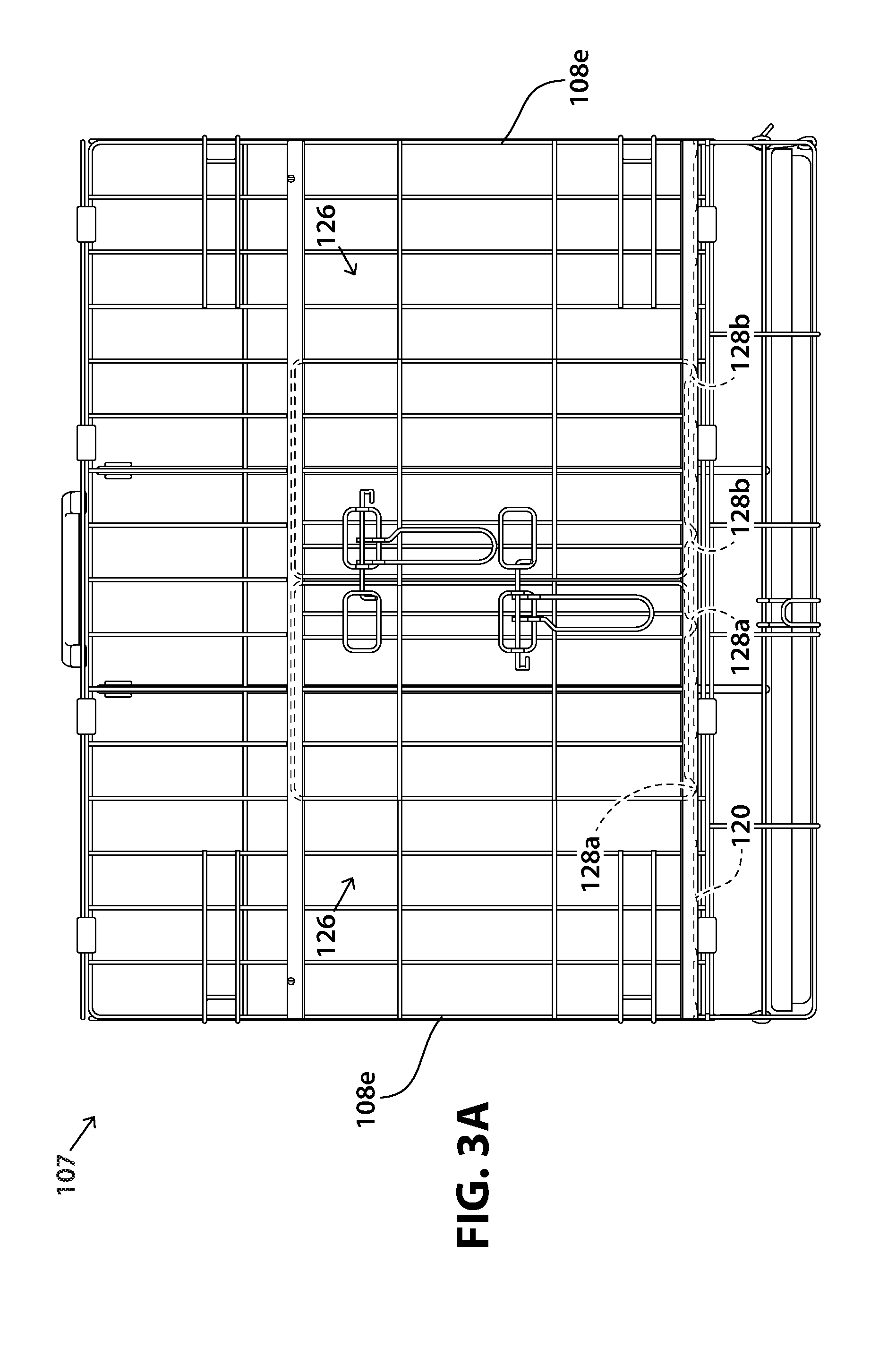
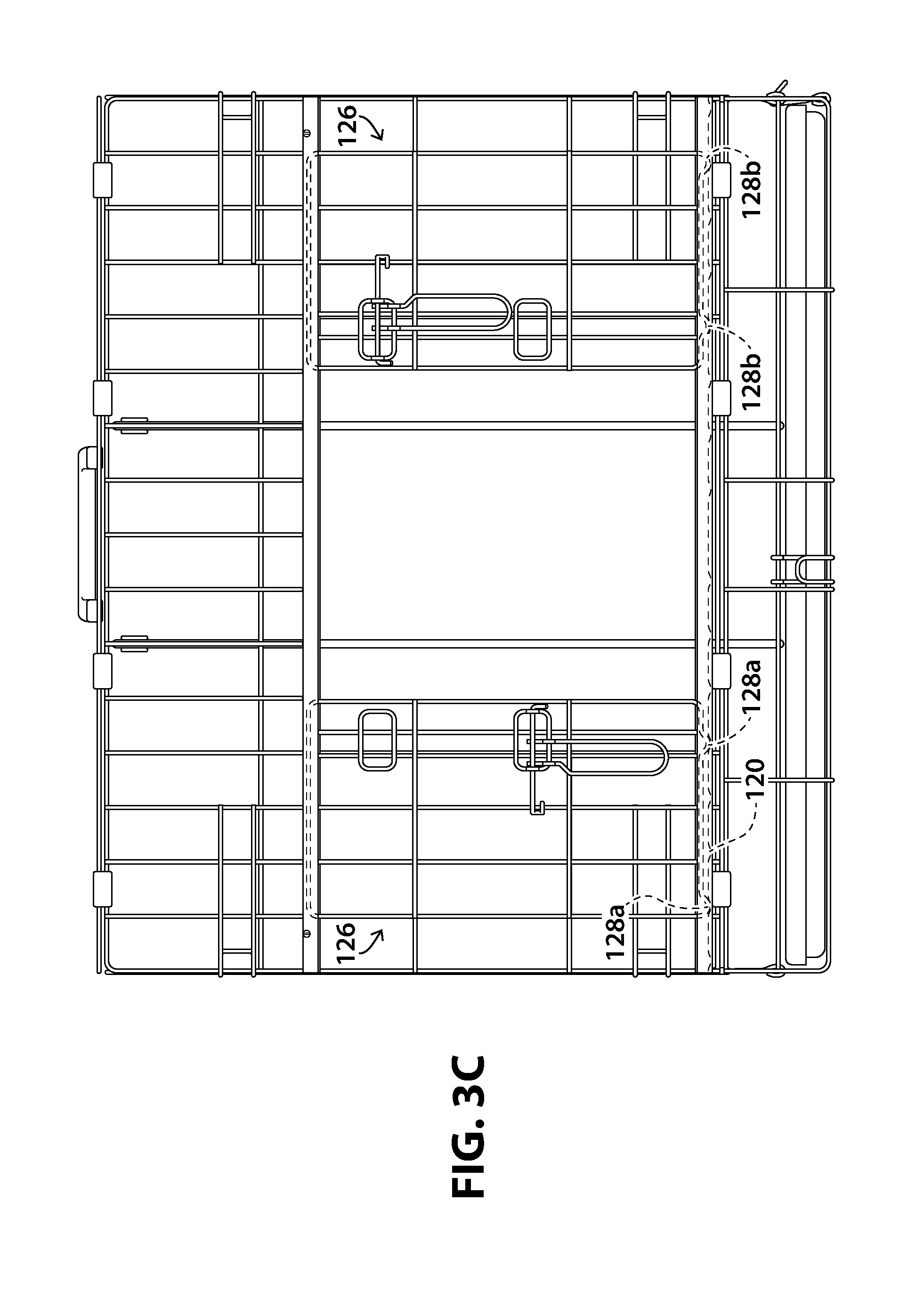
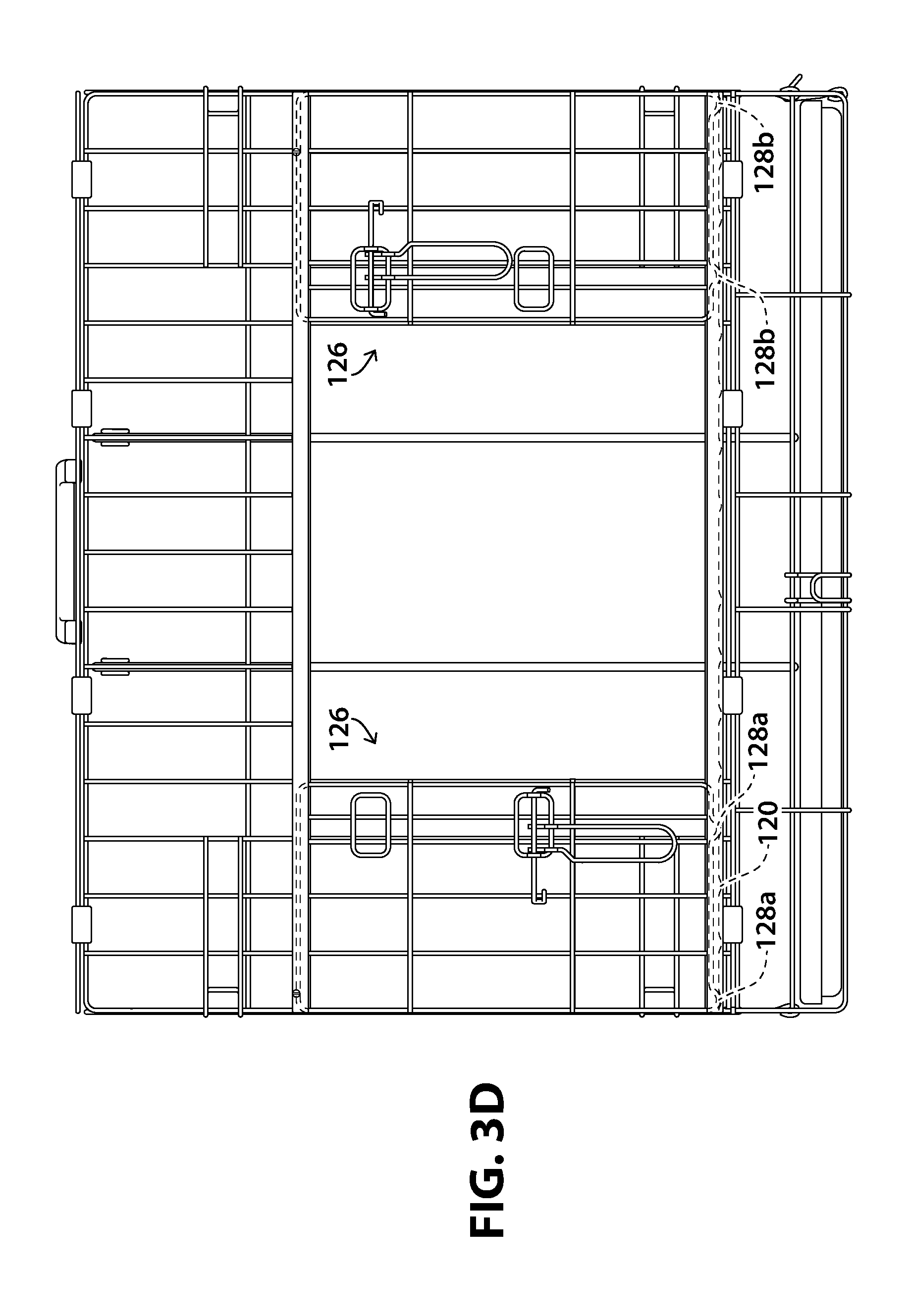
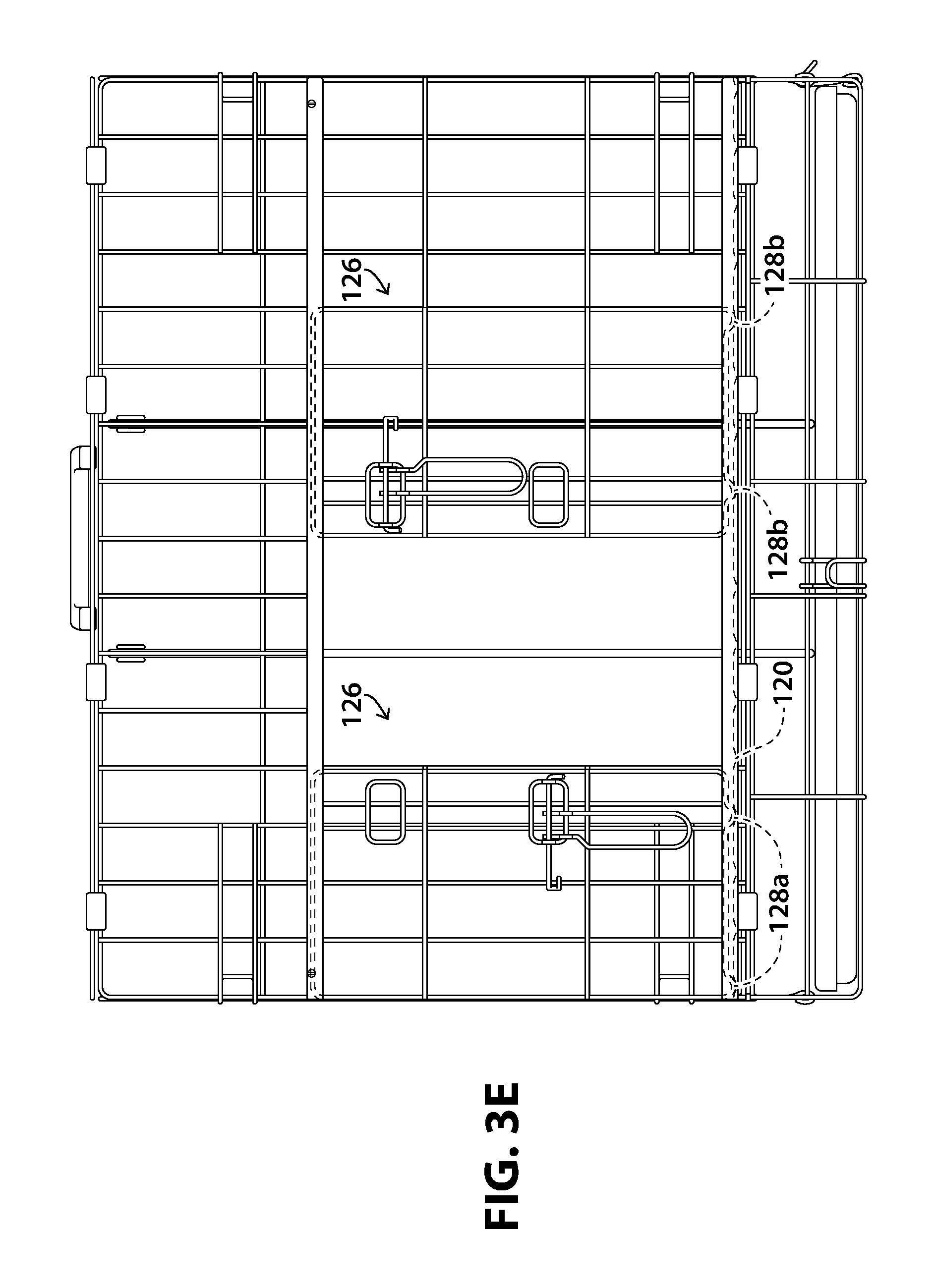
[0512] FIGS. 3A, 3B, 3C, 3D, and 3E illustrate front views of the low-friction door-corner-recess-arc-rail system, and the first and second multi-pet multi-position-double-door systems in various door-locking positions.
[0513] FIG. 3F illustrates a front view of the multi-pet-containing panel system without the first and second auto-indexing multi-position doors, and without the first and second movable crate dividers.
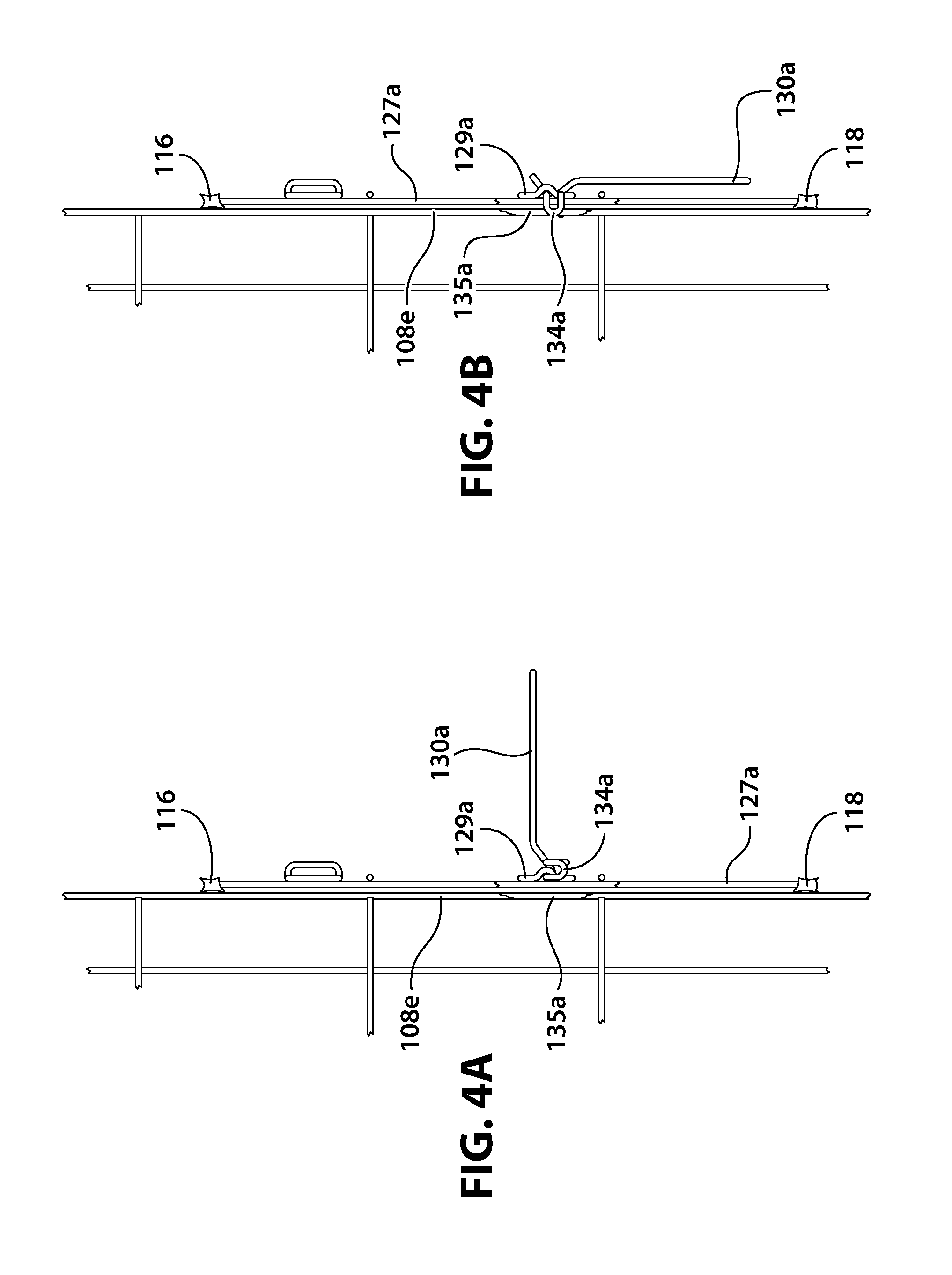
[0514] FIGS. 4A, 4B, 4C, 4D, 4E, 4F, and 4G illustrate side and perspective views of the interaction between the first push-rod levers, the first door-locking push-rod heads, the first multi-position push-rod-tail-locking tails, and the first multi-position push-rod-tail-locking wire, in locked and unlocked positions.
[0515] FIG. 5A illustrates a top view of the multi-pet-containing panel system, and the quick-assembly door-extracting-inserting system, especially the door extracting-inserting slots.
[0516] FIGS. 5B, 5C, and 5D illustrate front views of the installation of the first and second auto-indexing multi-position doors.
[0517] FIG. 6 illustrates a front view of the series of the door-corner-glider-locking recesses in the bottom low-friction rail, for positioning the first and second multi-position door-locking push-rod tails, to line up with the first and second multi-position push-rod-tail-locking wires.
[0518] FIG. 7A illustrates a side view of the top low-friction rail, bottom low-friction rail, and the door-blocking slot screws.
[0519] FIGS. 7B, and 7C illustrate sectional views of the relationship between the top and bottom low-friction rails, the first and second auto-indexing multi-position door-corner-gliders, and the multi-position door-corner-glider-locking recesses.
[0520] FIG. 7D illustrates a front view of the front panel, the first and second auto-indexing multi-position doors and the top and bottom low-friction rails.
[0521] FIGS. 7E and 7F illustrate sectional side views of the top and bottom low-friction rails and the side and bottom low-friction rail arcs.
[0522] FIG. 7G illustrates a front view of the auto-indexing multi-position door and the top and bottom low-friction rails.
[0523] FIG. 7H illustrates a sectional view of the bottom low-friction rail, and its respective bottom low-friction rail arcs, the auto-indexing multi-position door, and the door-corner-glider-locking recess.
[0524] FIGS. 8A and 8B illustrate front views of the first and second movable crate dividers within the multi-pet-containing panel system, to accommodate multiple pets.
[0525] FIGS. 9A, 9B, 9C, 9D, 9E, and 9F illustrate top, side, and front views of the mobile-grooming-tool-and-poop-bag-retaining handle system.
[0526] FIG. 10 illustrates a back view of the multi-pet-containing panel system, showing the rear panel.
[0527] FIGS. 11A and 11B illustrate front views of the multi-pet locking-tail-push-rod pet crate overcoming the gravitational forces when positioned on a moving, inclined vehicle floor, a non-moving, inclined driveway, or other stationary surface.
[0528] FIGS. 12A and 12B illustrate side and top views of the the slanted urine-storing-gutter tray, urine-storing gutters, and gutter ridges.
[0529] FIGS. 13A, 13B, 13C, illustrate front views of how to lock the first and second auto-indexing multi-position doors.
[0530] FIGS. 14A, 14B, 14C, 14D, and 14E illustrate front views of how to lock the first and second auto-indexing multi-position doors in multiple positions.
[0531] FIGS. 15A, 15B, 15C, 15D, 15E, and 15F illustrate front views of how to lock the first and second auto-indexing multi-position doors in multiple positions to the front panel in multiple positions.
[0532] FIGS. 16A, 16B, and 16C illustrate front views of how to assemble the first and second auto-indexing multi-position doors.
[0533] FIG. 17 illustrates a front view of how to lock the first and second auto-indexing multi-position doors in multiple positions.
[0534] FIGS. 18A and 18B illustrate a front view of a variation of how to assemble the first and second auto-indexing multi-position doors first, then weld the first and second push-rod levers thereon later.
[0535] FIGS. 19, 20, and 21 illustrate front views of variations of the multi-pet multi-position-double-door system.
[0536] FIG. 22 illustrates a side view of variations of the door extracting-inserting slots and the top and bottom low-friction rail arcs.
[0537] FIG. 23 illustrates a top view of a variation of the multi-pet locking-tail-push-rod pet crate having multi-pet multi-position-double-door systems on five sides.
[0538] FIG. 24 illustrates a front view of a variation of the multi-pet locking-tail-push-rod pet crate having multiple movable crate dividers, to accommodate multiple pets.
[0539] FIG. 25 illustrates a side view of a variation of the multi-pet locking-tail-push-rod pet crate having a swinging door system.
[0540] FIG. 26A illustrates a top view of a variation of the mobile-grooming-tool-and-poop-bag-retaining handle system and the quick-assembly door-extracting-inserting system.
[0541] FIG. 26B illustrates a front view of a variation of how to install the multi-pet multi-position-double-door system through one door-extracting-inserting slot.
[0542] FIG. 27 illustrates a side view of a variation of the Low-friction door-corner-recess-arc-rail system.
DETAILED DESCRIPTION OF THE INVENTION
[0543] The multi-pet locking-head-and-locking-tail-push-rod pet crate comprises: [0544] 1) Grooming-tool-poop-bag handle system, [0545] 2) Low-friction door-rail system, [0546] 3) Quick-assembly door system, and [0547] 4) Multi-position-double-locking-head-and-locking-tail multi-position-double-push-rod multi-position-double-door system.
Component
[0548] Referring to FIG. 1, FIG. 2A, FIG. 2B, FIG. 2C, FIG. 3A, FIG. 3B, FIG. 3C, FIG. 3D, FIG. 3E, FIG. 4A, FIG. 4B, FIG. 4C, FIG. 4D, FIG. 4E, FIG. 5A, FIG. 5B, FIG. 5C, FIG. 5D, FIG. 6, FIG. 7A, FIG. 7B, FIG. 7C, FIG. 7D, FIG. 7E, FIG. 7F, FIG. 7G, FIG. 711, FIG. 8A, FIG. 8B, FIG. 9A, FIG. 9B, FIG. 9C, FIG. 9D, FIG. 9E, FIG. 9F, FIG. 10, FIG. 11A, FIG. 11b, FIG. 12A, and FIG. 12B, the multi-pet locking-tail-push-rod pet crate, (having grooming-tool-poop-bag handle system, low-friction door-rail system, quick-assembly door system, and multi-position locking-head-and-locking-tail push-rod system), comprises: [0549] 1) Mobile-grooming-tool-and-poop-bag-retaining handle system 101, comprising: [0550] 2) Handle bridge 102, [0551] 3) Handle stabilizers 103, [0552] 4) Multi-grooming-tool-clamping handle channel 104, [0553] 5) Poop-bag-clamping handle clasps 105, and [0554] 6) Handle hooks 106; [0555] 7) Multi-pet-containing panel system 107, comprising: [0556] 8) Top, bottom, left, right, front, and rear panels 108a, 108b, 108c, 108d, 108e, and 108f, [0557] 9) Panel-locking hooks 109, [0558] 10) Panel-folding clamp 110, [0559] 11) Panel-coupling clamps 111, [0560] 12) First and second door openings 112a and 112b, [0561] 13) First and second movable crate dividers 113a and 113b, [0562] 14) Slanted urine-storing-gutter tray 114a, [0563] Urine-storing gutters 114b, and [0564] Gutter ridges 114c; [0565] 15) Low-friction door-corner-recess-arc-rail system 115, comprising: [0566] 16) Top low-friction rail 116, [0567] 17) Top low-friction rail arcs 117a, 117b, and 117c, [0568] 18) Bottom low-friction rail 118, [0569] 19) Bottom low-friction rail arcs 119a, 119b, and 119c, [0570] 20) Multi-position door-corner-glider-locking recesses 120, and [0571] 21) Central doorstop 121; [0572] 22) Quick-assembly door-extracting-inserting system 122, comprising: [0573] 23) Door extracting-inserting slots 123a and 123b, [0574] 24) Door-blocking slot screws 124a and 124b, and [0575] 25) Slot-screw holes 125a and 125b; and [0576] 26) Multi-pet multi-position-double-locking-head-and-locking-tail multi-position-double-door system 126, comprising: [0577] 27) First and second auto-indexing multi-position doors 127a and 127b, [0578] 28) First and second auto-indexing multi-position door-corner-gliders 128a and 128b, [0579] 29) First and second push-rod hinges 129a and 129b, [0580] 30) First and second push-rod levers 130a and 130b, [0581] 31) First and second push-rods 131a and 131b, [0582] 32) First and second door-locking push-rod heads 132a and 132b, [0583] 33) First and second push-rod-head-locking rings 133a and 133b, [0584] 34) First and second multi-position door-locking push-rod tails 134a and 134b, and [0585] 35) First and second multi-position push-rod-tail-locking wires 135a and 135b.
Material
[0586] Referring to FIG. 1, FIG. 2A, FIG. 2B, FIG. 2C, FIG. 3A, FIG. 3B, FIG. 3C, FIG. 3D, FIG. 3E, FIG. 4A, FIG. 4B, FIG. 4C, FIG. 4D, FIG. 4E, FIG. 5A, FIG. 5B, FIG. 5C, FIG. 5D, FIG. 6, FIG. 7A, FIG. 7B, FIG. 7C, FIG. 7D, FIG. 7E, FIG. 7F, FIG. 7G, FIG. 711, FIG. 8A, FIG. 8B, FIG. 9A, FIG. 9B, FIG. 9C, FIG. 9D, FIG. 9E, FIG. 9F, FIG. 10, FIG. 11A, FIG. 11b, FIG. 12A, and FIG. 12B: [0587] 1) Mobile-grooming-tool-and-poop-bag-retaining handle system 101 is made of the combined materials of its components. [0588] 2) Handle bridge 102 [0589] is made of plastic material. [0590] 3) Handle stabilizers 103 [0591] each are made of plastic material. [0592] 4) Multi-grooming-tool-clamping handle channel 104 [0593] is made of empty space. [0594] 5) Poop-bag-clamping handle clasps 105 [0595] each are made of plastic material. [0596] 6) Handle hooks 106 [0597] each are made of plastic material. [0598] 7) Multi-pet-containing panel system 107 is made of the combined materials of its components. [0599] 8) Top, bottom, left, right, front, and rear panels [0600] 108a, 108b, 108c, 108d, 108e, and 108f [0601] each are made of metallic material. [0602] 9) Panel-locking hooks 109 [0603] each are made of metallic material. [0604] 10) Panel-folding clamp 110 [0605] is made of metallic material. [0606] 11) Panel-coupling clamps 111 [0607] each are made of metallic material. [0608] 12) First and second door openings 112a and 112b [0609] each are made of empty space. [0610] 13) First and second movable crate dividers 113a and 113b [0611] each are made of metallic material. [0612] 14) Slanted urine-storing-gutter tray 114a [0613] is made of plastic material.
[0614] Urine-storing gutters 114b [0615] each are made of plastic material.
[0616] Gutter ridges 114c [0617] each are made of plastic material. [0618] 15) Low-friction door-corner-recess-arc-rail system 115 is made of the combined materials of its components. [0619] 16) Top low-friction rail 116 [0620] is made of metallic material. [0621] 17) Top low-friction rail arcs 117a, 117b, and 117c [0622] each are made of metallic material. [0623] 18) Bottom low-friction rail 118 [0624] is made of metallic material. [0625] 19) Bottom low-friction rail arcs 119a, 119b, and 119c [0626] each are made of metallic material. [0627] 20) Multi-position door-corner-glider-locking recesses 120 [0628] each are made of empty space material. [0629] 21) Central doorstop 121 [0630] is made of metallic material. [0631] 22) Quick-assembly door-extracting-inserting system 122 is made of the combined materials of its components. [0632] 23) Door extracting-inserting slots 123a and 123b each are made of empty space. [0633] 24) Door-blocking slot screws 124a and 124b [0634] each are made of metallic material. [0635] 25) Slot-screw holes 125a and 125b [0636] each are made of empty space. [0637] 26) Multi-pet multi-position-double-door system 126 is made of the combined materials of its components. [0638] 27) First and second auto-indexing multi-position doors 127a and 127b each are made of metallic material. [0639] 28) First and second auto-indexing multi-position door-corner-gliders 128a and 128b [0640] each are made of metallic material. [0641] 29) First and second push-rod hinges 129a and 129b [0642] each are made of metallic material. [0643] 30) First and second push-rod levers 130a and 130b [0644] each are made of metallic material. [0645] 31) First and second push-rods 131a and 131b [0646] each are made of metallic material. [0647] 32) First and second door-locking push-rod heads 132a and 132b [0648] each are made of metallic material. [0649] 33) First and second push-rod-head-locking rings 133a and 133b [0650] each are made of metallic material. [0651] 34) First and second multi-position door-locking push-rod tails 134a and 134b [0652] each are made of metallic material. [0653] 35) First and second multi-position push-rod-tail-locking wires 135a and 135b [0654] each are made of metallic material.
Shape
[0655] Referring to FIG. 1, FIG. 2A, FIG. 2B, FIG. 2C, FIG. 3A, FIG. 3B, FIG. 3C, FIG. 3D, FIG. 3E, FIG. 4A, FIG. 4B, FIG. 4C, FIG. 4D, FIG. 4E, FIG. 5A, FIG. 5B, FIG. 5C, FIG. 5D, FIG. 6, FIG. 7A, FIG. 7B, FIG. 7C, FIG. 7D, FIG. 7E, FIG. 7F, FIG. 7G, FIG. 7H, FIG. 8A, FIG. 8B, FIG. 9A, FIG. 9B, FIG. 9C, FIG. 9D, FIG. 9E, FIG. 9F, FIG. 10, FIG. 11A, FIG. 11b, FIG. 12A, and FIG. 12B: [0656] 1) Mobile-grooming-tool-and-poop-bag-retaining handle system 101 has the combined shapes of its components. [0657] 2) Handle bridge 102 [0658] has an I shape with a C-shaped cross-section. [0659] 3) Handle stabilizers 103 [0660] each have a cylindrical shape. [0661] 4) Multi-grooming-tool-clamping handle channel 104 [0662] has a cylindrical shape. [0663] 5) Poop-bag-clamping handle clasps 105 [0664] each have a C shape. [0665] 6) Handle hooks 106 [0666] each have a C shape. [0667] 7) Multi-pet-containing panel system 107 has the combined shapes of its components. [0668] 8) Top, bottom, left, right, front, and rear panels [0669] 108a, 108b, 108c, 108d, 108e, and 108f [0670] each have a rectangular shape. [0671] 9) Panel-locking hooks 109 [0672] each have a J shape. [0673] 10) Panel-folding clamp 110 [0674] has a C shape. [0675] 11) Panel-coupling clamps 111 [0676] each have a C shape. [0677] 12) First and second door openings 112a and 112b [0678] each have a rectangular shape. [0679] 13) First and second movable crate dividers 113a and 113b [0680] each have a rectangular shape. [0681] 14) Slanted urine-storing-gutter tray 114a [0682] has a rectangular shape.
[0683] Urine-storing gutters 114b [0684] each have an O shape with a U-shaped cross-section.
[0685] Gutter ridges 114c [0686] each have an I shape. [0687] 15) Low-friction door-corner-recess-arc-rail system 115 has the combined shapes of its components. [0688] 16) Top low-friction rail 116 [0689] has an I shape with a U-shaped cross-section. [0690] 17) Top low-friction rail arcs 117a, 117b, and 117c [0691] each have a C shape. [0692] 18) Bottom low-friction rail 118 [0693] has an I shape with a U-shaped cross-section. [0694] 19) Bottom low-friction rail arcs 119a, 119b, and 119c [0695] each have a C shape. [0696] 20) Multi-position door-corner-glider-locking recesses 120 [0697] each have a cup shape. [0698] 21) Central doorstop 121 [0699] has a I shape. [0700] 22) Quick-assembly door-extracting-inserting system 122 has the combined shapes of its components. [0701] 23) Door extracting-inserting slots 123a and 123b [0702] each have a rectangular shape. [0703] 24) Door-blocking slot screws 124a and 124b [0704] each have a screw shape. [0705] 25) Slot-screw holes 125a and 125b.
[0706] each have a circular shape. [0707] 26) Multi-pet multi-position-double-door system has the combined shapes of its components. [0708] 27) First and second auto-indexing multi-position doors 127a and 127b [0709] each have a rectangular shape. [0710] 28) First and second auto-indexing multi-position door-corner-gliders 128a and 128b [0711] each have a U shape. [0712] 29) First and second push-rod hinges 129a and 129b [0713] each have an O shape. [0714] 30) First and second push-rod levers 130a and 130b [0715] each have a G shape. [0716] 31) First and second push-rods 131a and 131b [0717] each have a I shape. [0718] 32) First and second door-locking push-rod heads 132a and 132b [0719] each have an L shape. [0720] 33) First and second push-rod-head-locking rings 133a and 133b [0721] each have a rectangular-ring shape. [0722] 34) First and second multi-position door-locking push-rod tails 134a and 134b [0723] each have a U shape. [0724] 35) First and second multi-position push-rod-tail-locking wires 135a and 135b [0725] each have an I shape.
Connection
[0726] Referring to FIG. 1, FIG. 2A, FIG. 2B, FIG. 2C, FIG. 3A, FIG. 3B, FIG. 3C, FIG. 3D, FIG. 3E, FIG. 4A, FIG. 4B, FIG. 4C, FIG. 4D, FIG. 4E, FIG. 5A, FIG. 5B, FIG. 5C, FIG. 5D, FIG. 6, FIG. 7A, FIG. 7B, FIG. 7C, FIG. 7D, FIG. 7E, FIG. 7F, FIG. 7G, FIG. 711, FIG. 8A, FIG. 8B, FIG. 9A, FIG. 9B, FIG. 9C, FIG. 9D, FIG. 9E, FIG. 9F, FIG. 10, FIG. 11A, FIG. 11b, FIG. 12A, and FIG. 12B: [0727] 1) Mobile-grooming-tool-and-poop-bag-retaining handle system 101 has the combined connections of its components. [0728] 2) Handle bridge 102 [0729] is molded to handle stabilizers 103. [0730] 3) Handle stabilizers 103 [0731] respectively are molded to handle hooks 106. [0732] 4) Multi-grooming-tool-clamping handle channel 104 [0733] is molded inside handle bridge 102. [0734] 5) Poop-bag-clamping handle clasps 105 [0735] respectively are molded in handle stabilizers 103. [0736] 6) Handle hooks 106 [0737] respectively are hooked on top panel 108a. [0738] 7) Multi-pet-containing panel system 107 has the combined connections of its components. [0739] 8) Top, bottom, left, right, front, and rear panels [0740] 108a, 108b, 108c, 108d, 108e, and 108f, [0741] respectively are hooked together. [0742] 9) Panel-locking hooks 109 [0743] respectively are hooked on top, left, right, front, and rear panels [0744] 108a, 108c, 108d, 108e, and 108f. [0745] 10) Panel-folding clamp 110 [0746] is clamped on top, bottom, left, right, front, and rear panels [0747] 108a, 108b, 108c, 108d, 108e, and 108f. [0748] 11) Panel-coupling clamps 111 [0749] respectively are clamped on top, bottom, left, right, front, and rear panels [0750] 108a, 108b, 108c, 108d, 108e, and 108f. [0751] 12) First and second door openings 112a and 112b [0752] respectively are created inside front panel 108e. [0753] 13) First and second movable crate dividers 113a and 113b [0754] respectively are disposed inside top, bottom, left, right, front, and rear panels 108a, 108b, 108c, 108d, 108e, and 108f. [0755] 14) Slanted urine-storing-gutter tray 114a [0756] is disposed on bottom panel 108b.
[0757] Urine-storing gutters 114b [0758] respectively are molded around slanted urine-storing-gutter tray 114a.
[0759] Gutter ridges 114c [0760] respectively are molded inside urine-storing gutters 114b. [0761] 15) Low-friction door-corner-recess-arc-rail system 115 has the combined connections of its components. [0762] 16) Top low-friction rail 116 [0763] is welded to front panel 108e. [0764] 17) Top low-friction rail arcs 117a, 117b, and 117c [0765] respectively are cast in top low-friction rail 116. [0766] 18) Bottom low-friction rail 118 [0767] is welded to front panel 108e. [0768] 19) Bottom low-friction rail arcs 119a, 119b, and 119c [0769] respectively are cast in bottom low-friction rail 118. [0770] 20) Multi-position door-corner-glider-locking recesses 120 [0771] respectively are formed in bottom low-friction rail 118. [0772] 21) Central doorstop 121 [0773] is welded to bottom low-friction rail 118. [0774] 22) Quick-assembly door-extracting-inserting system 122 has the combined connections of its components. [0775] 23) Door extracting-inserting slots 123a and 123b [0776] respectively are formed in top low-friction rail 116. [0777] 24) Door-blocking slot screws 124a and 124b [0778] respectively are screwed into slot-screw holes 125a and 125b. [0779] 25) Slot-screw holes 125a and 125b [0780] respectively are drilled in top low-friction rail 116. [0781] 26) Multi-pet multi-position-double-door system 126 has the combined connections of its components. [0782] 27) First and second auto-indexing multi-position doors 127a and 127b [0783] respectively and slidably are inserted between top low-friction rail 116 and bottom low-friction rail 118. [0784] 28) First and second auto-indexing multi-position door-corner-gliders 128a and 128b [0785] respectively are cast to first and second auto-indexing multi-position doors 127a and 127b. [0786] 29) First and second push-rod hinges 129a and 129b [0787] respectively are welded to first and second auto-indexing multi-position doors 127a and 127b. [0788] 30) First and second push-rod levers 130a and 130b [0789] respectively are welded to first and second push-rod hinges 129a and 129b. [0790] 31) First and second push-rods 131a and 131b [0791] respectively and rotatably are attached to first and second push-rod hinges 129a and 129b. [0792] 32) First and second door-locking push-rod heads 132a and 132b [0793] respectively are cast to first and second push-rods 131a and 131b. [0794] 33) First and second push-rod-head-locking rings 133a and 133b [0795] respectively are welded to first and second auto-indexing multi-position doors 127a and 127b. [0796] 34) First and second multi-position door-locking push-rod tails 134a and 134b [0797] respectively are cast to first and second push-rods 131a and 131b. [0798] 35) First and second multi-position push-rod-tail-locking wires 135a and 135b [0799] respectively are welded to front panel 108e.
Function
[0800] Referring to FIG. 13A, FIG. 13B, FIG. 13C, FIG. 14A, FIG. 14B, FIG. 14C, FIG. 14D, FIG. 14E, FIG. 15A, FIG. 15B, FIG. 15C, FIG. 15D, FIG. 15E, FIG. 15F, FIG. 16A, FIG. 16B, FIG. 16C, and FIG. 17: [0801] 1) Mobile-grooming-tool-and-poop-bag-retaining handle system 101 is for performing the combined functions of its components. [0802] 2) Handle bridge 102 is for: [0803] Being held on to carry the multi-pet locking-tail push-rod pet crate. [0804] 3) Handle stabilizers 103 respectively are for: [0805] Providing vertical support between the ends of handle bridge 102. [0806] 4) Multi-grooming-tool-clamping handle channel 104 is for: [0807] a) Insertably containing multi-grooming tools; [0808] b) Being used as a hook, [0809] to store multi-grooming tools [0810] (see FIG. 9E); [0811] c) Being used as a hook, [0812] to store pet toys [0813] (see FIG. 9E); [0814] d) Being used as a hook, [0815] to hold leashes [0816] (see FIG. 9E); and [0817] e) Being used as a clamp, [0818] to hold papers and documents [0819] (see FIG. 9E). [0820] 5) Poop-bag-clamping handle clasps 105 respectively are for: [0821] a) Securely fastening poop bags to handle bridge 102; [0822] b) Being used as hooks, [0823] to securely fasten poop bags to handle bridge 102 [0824] (see FIG. 9F); [0825] c) Being used as hooks, [0826] to store multi-grooming tools [0827] (see FIG. 9F); [0828] d) Being used as hooks, [0829] to hold pet toys [0830] (see FIG. 9F); and [0831] e) Being used as hooks, [0832] to hold leashes [0833] (see FIG. 9F). [0834] 6) Handle hooks 106 respectively are for: [0835] Detachably connecting handle bridge 102 to top panel 108a. [0836] 7) Multi-pet-containing panel system 107 is for performing the combined functions of its components. [0837] 8) Top, bottom, left, right, front, and rear panels [0838] 108a, 108b, 108c, 108d, 108e, and 108f respectively are for: [0839] Functioning as a roof, walls, and floor, [0840] to create a temporary pet enclosure. [0841] 9) Panel-locking hooks 109 respectively are for: [0842] Securably fastening top, bottom, left, right, front, and rear panels 108a, 108b, 108c, 108d, 108e, and 108f together. [0843] 10) Panel-folding clamp 110 is for: [0844] Foldably clamping multi-pet-containing panel system 107 together, [0845] to allow convenient storage and transport to multiple locations. [0846] 11) Panel-coupling clamps 111 respectively are for: [0847] Hingably and foldably coupling top, bottom, left, right, front, and rear panels 108a, 108b, 108c, 108d, 108e, and 108f together. [0848] 12) First and second door openings 112a and 112b respectively are for: [0849] a) Allowing first and second auto-indexing multi-position doors 127a and 127b to be locked in multiple positions; and [0850] b) Allowing multiple pets to enter and exit [0851] (see FIG. 3B, FIG. 3C, FIG. 3D, and FIG. 3E). [0852] 13) First and second movable crate dividers 113a and 113b respectively are for: [0853] a) Creating multiple pet-containing compartments, [0854] to accommodate multiple pets [0855] (see FIG. 8A and FIG. 8B); [0856] b) Creating multiple sized pet-containing compartments, [0857] to accommodate pet growth from puppy to adult stage [0858] (see FIG. 8A and FIG. 8B); and [0859] c) Creating multiple sized pet-containing compartments, [0860] to accommodate large and small pets simultaneously [0861] (see FIG. 8A and FIG. 8B). [0862] 14) Slanted urine-storing-gutter tray 114a is for: [0863] a) Draining the urine into urine-storing-gutters 114b, [0864] to keep slanted urine-storing-gutter tray 114a dry [0865] (see FIG. 12A and FIG. 12B); [0866] b) Comfortably accommodating pets, [0867] to allow pets to sit, stand, play, rest, and sleep thereon [0868] (see FIG. 12A and FIG. 12B); [0869] c) Conveniently keeping pets away and not on their urine, [0870] to keep pets dry; and [0871] d) Conveniently keeping pets away and not on their urine, [0872] to prevent pets from getting diseases and infections caused by their own urine.
[0873] Urine-storing gutters 114b respectively are for: [0874] a) Storing urine run-off from slanted urine-storing-gutter tray, [0875] to keep slanted urine-storing-gutter tray 114a dry [0876] (see FIG. 12A and FIG. 12B); [0877] b) Conveniently keeping pets away and not on their urine, [0878] to keep the pets dry; [0879] c) Conveniently keeping pets away and not on their urine, [0880] to prevent pets from getting diseases and infections; and [0881] d) Allowing quick and easy cleaning.
[0882] Gutter ridges 114c is for: [0883] a) Supporting a pet's paws while stepping upon [0884] to help pets to be comfortable and safe [0885] (see FIG. 12A and FIG. 12B); [0886] b) Conveniently keeping pets away and not on their urine, [0887] to keep pets dry; [0888] c) Providing protrusions and recesses for urine to flow therein, [0889] to separate urine from pet's area; and [0890] d) Preventing pets from submersion in urine [0891] to avoid infections and disease. [0892] 15) Low-friction door-corner-recess-arc-rail system 115 is for performing the combined functions of its components. [0893] 16) Top low-friction rail 116 is for: [0894] a) Slidably securing first and second auto-indexing multi-position doors 127a and 127b [0895] (see FIG. 7A. FIG. 7B and FIG. 7E); [0896] b) Providing low-friction surfaces, [0897] to enable easy sliding motions of first and second auto-indexing multi-position doors 127a and 127b [0898] (see FIG. 7A. FIG. 7B and FIG. 7E); [0899] c) Providing top low-friction rail arcs 117a, 117b, and 117c to allow easy sliding motions of first and second auto-indexing multi-position doors 127a and 127b [0900] (see FIG. 7A. FIG. 7B and FIG. 7E); and [0901] d) Providing top low-friction rail arcs 117a, 117b, and 117c; [0902] to maintain minimum surface contact, for minimum friction [0903] (see FIG. 7A. FIG. 7B and FIG. 7E). [0904] 17) Top low-friction rail arcs 117a, 117b, and 117c respectively are for: [0905] a) Reducing surface contact, thereby lowering friction between top low-friction rail 116 and first and second auto-indexing multi-position doors 127a and 127b [0906] (see FIG. 7E); [0907] b) Slidably securing the tops of first and second auto-indexing multi-position doors 127a and 127b, [0908] to provide a secure channel for first and second auto-indexing multi-position doors 127a and 127b to easily slide horizontally [0909] (see FIG. 7E); and [0910] c) Providing a tall rear wall of top low-friction rail arc 117a [0911] to minimize potential fur and paws being caught in top low-friction rail 116. [0912] 18) Bottom low-friction rail 118 is for: [0913] a) Slidably securing first and second auto-indexing multi-position doors 127a and 127b [0914] (see FIG. 7C, FIG. 7F and FIG. 711); [0915] b) Providing low-friction surfaces, [0916] to enable easy sliding motions of first and second auto-indexing multi-position doors 127a and 127b [0917] (see FIG. 7C, FIG. 7F and FIG. 711); [0918] b) Providing bottom low-friction rail arcs 119a, 119b, and 119c to allow easy sliding motions of first and second auto-indexing multi-position doors 127a and 127b [0919] (see FIG. 7C, FIG. 7F and FIG. 711); [0920] d) Providing bottom low-friction rail arcs 119a, 119b, and 119c; [0921] to maintain minimum surface contact, for minimum friction [0922] (see FIG. 7C, FIG. 7F and FIG. 711). [0923] 19) Bottom low-friction rail arcs 119a, 119b, and 119c respectively are for: [0924] a) Reducing surface contact, thereby lowering friction between bottom low-friction rail 118 and first and second auto-indexing multi-position doors 127a and 127b [0925] (see FIG. 7C, FIG. 7F and FIG. 711); [0926] b) Slidably securing the tops of first and second auto-indexing multi-position doors 127a and 127b, [0927] to provide a secure channel for first and second auto-indexing multi-position doors 127a and 127b to easily slide horizontally [0928] (see FIG. 7C, FIG. 7F and FIG. 711); and [0929] c) Providing a tall rear wall of bottom low-friction rail arc 119a [0930] to minimize potential fur and paws being [0931] caught in bottom low-friction rail 118. [0932] 20) Multi-position door-corner-glider-locking recesses 120 respectively are for: [0933] a) Locking first and second auto-indexing multi-position door-corner-gliders 128a and 128b therein [0934] to horizontally and slantedly lock first and second auto-indexing multi-position doors 127a and 127b in multiple horizontal or slanted and stationary or moving positions [0935] in the direction of arrows 136a and 136b [0936] (see FIG. 6, FIG. 7C, FIG. 7D, FIG. 7F, FIG. 7G, FIG. 711, and FIG. 17); [0937] b) Allowing multiple locked horizontal positions for first and second auto-indexing multi-position doors 127a and 127b, [0938] at multiple locations [0939] (see FIG. 6, FIG. 7C, FIG. 7D, and FIG. 7G); [0940] c) Precisely self-adjusting each available incremental door position [0941] (see FIG. 6, FIG. 7C, FIG. 7D, and FIG. 7G); and [0942] d) Making door position adjustments quicker and easier for the user. [0943] 21) Central doorstop 121 is for: [0944] Preventing further movement of first and second auto-indexing multi-position doors 127a and 127b. [0945] 22) Quick-assembly door-extracting-inserting system 122 is for performing the combined functions of its components. [0946] 23) Door extracting-inserting slots 123a and 123b respectively are for: [0947] a) Quickly assembling first and second auto-indexing multi-position doors 127a and 127b by inserting them therethrough and lifting them up then down in the direction of the arrows 137a, 137b, 138a, and 138b [0948] (see FIG. 5A, FIG. 5B, FIG. 5D, FIG. 5E, FIG. 16A, FIG. 16B, and FIG. 16C); and [0949] b) Creating an access opening, [0950] to extract first and second auto-indexing multi-position doors 127a and 127b during manufacturing and by the user [0951] (see FIG. 5C). [0952] 24) Door-blocking slot screws 124a and 124b respectively are for: [0953] Blocking first and second auto-indexing multi-position doors 127a and 127b after the assembly, [0954] to prevent first and second auto-indexing multi-position doors 127a and 127b from vertical extraction through door extracting-inserting slots 123a and 123b. [0955] 25) Slot-screw holes 125a and 125b respectively are for: [0956] Receiving door-blocking slot screws 124a and 124b. [0957] 26) Multi-pet multi-position-double-door system 126 is for performing the combined functions of its components. [0958] 27) First and second auto-indexing multi-position doors 127a and 127b respectively are for: [0959] a) Locking in multiple pets and customizing each pet's exiting privileges in direction of arrows 139a and 139b [0960] (see FIG. 14A, FIG. 14B, FIG. 14C, FIG. 14D, and FIG. 14E); [0961] b) Locking in multiple pets and customizing each pet's entrance privilege; [0962] c) Limiting the entrance to predetermined size pets; [0963] d) Protecting smaller pets against larger predator's entrance while giving entrance-exit freedom to the smaller pet; and [0964] e) Expanding the number of divided sections with each having a customizable entrance. [0965] 28) First and second auto-indexing multi-position door-corner-gliders 128a and 128b respectively are for: [0966] a) Reducing friction to sliding movement of first and second auto-indexing multi-position doors 127a and 127b; [0967] b) Precisely stopping door at incremental door positions; [0968] c) Providing a precise alignment for multi-position door-locking push-rod tails 134a and 134b with multi-position push-rod-tail-locking wires 135a and 135b, so that locking action requires no user judgment; [0969] d) Eliminating door lubrication maintenance; and [0970] e) Providing two equal points of contact and balance for easy sliding movements. [0971] 29) First and second push-rod hinges 129a and 129b respectively are for: [0972] Hingedly securing first and second push-rods 131a and 131b to first and second auto-indexing multi-position doors 127a and 127b. [0973] 30) First and second push-rod levers 130a and 130b respectively are for: [0974] a) Locking and unlocking first and second auto-indexing multi-position doors 127a and 127b; [0975] b) Sliding first and second push-rods 131a and 131b and 127b; [0976] c) Sliding first and second auto-indexing multi-position doors 127a and 127b from side to side; and [0977] d) Self-securing locking function, [0978] to safely lock while distracted or unattended. [0979] 31) First and second push-rods 131a and 131b respectively are for: [0980] slidably acting as a rigid connection between first and second multi-position door-locking push-rod tails 134a and 134b, and first and second door-locking push-rod heads 132a and 132b. [0981] 32) First and second door-locking push-rod heads 132a and 132b respectively are for: [0982] a) Locking onto first and second push-rod-head-locking rings 133a and 133b; [0983] b) Unlocking from first and second push-rod-head-locking rings 133a and 133b. [0984] 33) First and second push-rod-head-locking rings 133a and 133b respectively are for: [0985] Locking onto first and second door-locking push-rod heads 132a. [0986] 34) First and second multi-position door-locking push-rod tails 134a and 134b [0987] respectively are for: [0988] a) Horizontally and slantedly locking and self-aligning positions of first and second auto-indexing multi-position doors 127a and 127b to respectively first and second multi-position push-rod-tail-locking wires 135a and 135b, in multiple horizontal or slanted and stationary or moving positions, by moving [0989] in the direction of the arrows 140a, 140b, 141a, 141b, 142a, and 142b, to disengage first and second door-locking push-rod heads 132a and 132b from first and second push-rod-head-locking rings 133a and 133b. [0990] (see FIG. 2A, FIG. 2B, FIG. 2C, FIG. 3A, FIG. 3B, FIG. 3C, FIG. 3D, FIG. 3E, FIG. 3F, FIG. 13A, FIG. 13B, and FIG. 13C); [0991] b) Locking first and second auto-indexing multi-position doors 127a and 127b to front panel 108e, in multiple horizontal or slanted and stationary or moving positions, by moving [0992] in the direction of the arrows 143a and 143b [0993] to lock onto first and second multi-position push-rod-tail-locking wires 135a and 135b [0994] (see FIG. 15A, FIG. 15B, FIG. 15C, FIG. 15D, FIG. 15E, and FIG. 15F); [0995] c) Allowing first and second auto-indexing multi-position doors 127a and 127b to maintain a closed, locked, or open position when the multi-pet locking-tail-push-rod pet crate is situated on: [0996] A non-moving, flat house floors; [0997] A non-moving, inclined driveway or other surface; [0998] A moving vehicle floor; [0999] A moving, upwardly inclined vehicle floor; and [1000] A moving, downwardly inclined vehicle floor; [1001] Bumped or pushed by an object; [1002] Shaken by an energetic pet; and [1003] Moved or relocated [1004] (see FIG. 11A and FIG. 11B); [1005] d) Allowing minimal materials to manufacture; and [1006] e) Allowing minimal manufacturing resources, [1007] to save labor, time, material, and money. [1008] 35) First and second multi-position push-rod-tail-locking wires 135a and 135b [1009] respectively are for: [1010] Providing multiple locations to which to horizontally and slantedly lock first and second multi-position door-locking push-rod tails 134a and 134b, [1011] to provide multiple horizontal and slanted locking locations for first and second auto-indexing multi-position doors 127a and 127b [1012] (see FIG. 2A, FIG. 2B, FIG. 2C, FIG. 13A, FIG. 13B, and FIG. 13C).
Variation
[1013] Any component of the multi-pet locking-tail push-rod pet crate can have any shape and size. Any component of the multi-pet locking-tail push-rod pet crate can be made of any material(s). [1014] FIGS. 18A and 18B illustrate a front view of a variation of how to assemble the first and second auto-indexing multi-position doors first, then weld the first and second push-rod levers thereon later. [1015] FIGS. 19, 20, and 21 illustrate front views of variations of multi-pet multi-position-double-door system 126. [1016] FIG. 22 illustrates a side view of variations of the door extracting-inserting slots and the top and bottom low-friction rail arcs. [1017] FIG. 23 illustrates a top view of a variation of the multi-pet locking-tail-push-rod pet crate having multi-pet multi-position-double-door systems on five sides. [1018] FIG. 24 illustrates a front view of a variation of the multi-pet locking-tail-push-rod pet crate having multiple movable crate dividers, to accommodate multiple pets. [1019] FIG. 25 illustrates a side view of a variation of the multi-pet locking-tail-push-rod pet crate having a swinging door system. [1020] FIG. 26A illustrates a top view of a variation of mobile-grooming-tool-and-poop-bag-retaining handle system 101 and quick-assembly door-extracting-inserting system 122. [1021] FIG. 26B illustrates a front view of a variation of how to install multi-pet multi-position-double-door system 126 through one of door extracting-inserting slots 123a and 123b. [1022] FIG. 27 illustrates a side view of a variation of low-friction door-corner-recess-arc-rail system 115.
MAJOR ADVANTAGES OF THE INVENTION
[1023] The present invention substantially departs from the conventional concepts and designs of the prior art. In doing so, the present invention provides a multi-pet locking-head-and-locking-tail-push-rod pet crate (having: a) Grooming-tool-poop-bag handle system, b) Low-friction door-rail system, c) Quick-assembly door system, and d) Multi-position locking-head-and-locking-tail push-rod system), having many unique and significant features, functions, and advantages, which overcome all the disadvantages of the prior art, as follows: [1024] 1) It is an object of the new invention to provide a multi-pet locking-head-and-locking-tail-push-rod pet crate, having [1025] multi-grooming-tool-clamping handle channel 104. [1026] Therefore, the multi-pet locking-head-and-locking-tail-push-rod pet crate: [1027] a) Can be used as a hook, [1028] to store multi-grooming tools [1029] (see FIG. 9E); [1030] b) Can be used as a hook, [1031] to store pet toys [1032] (see FIG. 9E); [1033] c) Can be used as a hook, [1034] to hold leashes [1035] (see FIG. 9E); and [1036] d) Can be used as a clamp, [1037] to hold papers and documents [1038] (see FIG. 9E). [1039] 2) It is another object of the new invention to provide a multi-pet locking-head-and-locking-tail-push-rod pet crate, having [1040] poop-bag-clamping handle clasps 105. [1041] Therefore, the multi-pet locking-head-and-locking-tail-push-rod pet crate: [1042] a) Can be used as hooks, [1043] to securely fasten poop bags to handle bridge 102 [1044] (see FIG. 9F); [1045] b) Can be used as hooks, [1046] to store multi-grooming tools [1047] (see FIG. 9F); [1048] c) Can be used as hooks, [1049] to hold pet toys [1050] (see FIG. 9F); and [1051] d) Can be used as hooks, [1052] to hold leashes [1053] (see FIG. 9F). [1054] 3) It is still another object of the new invention to provide a multi-pet locking-head-and-locking-tail-push-rod pet crate, having [1055] first and second door openings 112a and 112b. [1056] Therefore, the multi-pet locking-head-and-locking-tail-push-rod pet crate: [1057] a) Can be locked in multiple positions, [1058] to allow multiple pets to enter and exit [1059] (see FIG. 3B, FIG. 3C, FIG. 3D, and FIG. 3E,); [1060] b) Can be locked in multiple positions, [1061] to allow pets of various sizes to enter and exit [1062] (see FIG. 3B, FIG. 3C, FIG. 3D, and FIG. 3E,); [1063] c) Can be locked in multiple positions, [1064] to separately allow access to multiple pet-containing compartments [1065] (see FIG. 8A, and FIG. 8B,); and [1066] d) Can be locked in multiple positions, [1067] to provide security to multiple pets [1068] (see FIG. 8A, and FIG. 8B,). [1069] 4) It is a further object of the new invention to provide a multi-pet locking-head-and-locking-tail-push-rod pet crate, having [1070] first and second movable crate dividers 113a and 113b. [1071] Therefore, the multi-pet locking-head-and-locking-tail-push-rod pet crate: [1072] a) Can create multiple pet-containing compartments, [1073] to accommodate multiple pets [1074] (see FIG. 8A and FIG. 8B); [1075] b) Can provide separation to pets, [1076] to keep pets safe from each other [1077] (see FIG. 8A and FIG. 8B); [1078] c) Can create multiple sized pet-containing compartments, [1079] to accommodate pet growth from puppy to adult stage; and [1080] d) Can create multiple sized pet-containing compartments, [1081] to accommodate large and small pets simultaneously. [1082] 5) It is an even further object of the new invention to provide a multi-pet locking-head-and-locking-tail-push-rod pet crate, having [1083] a slanted urine-storing-gutter tray 114a. [1084] Therefore, the multi-pet locking-head-and-locking-tail-push-rod pet crate: [1085] a) Can drain urine into urine-storing-gutters 114b, [1086] to keep slanted urine-storing-gutter tray 114a dry [1087] (see FIG. 12A and FIG. 12B); [1088] b) Can comfortably accommodate pets, [1089] to allow pets to sit, stand, play, rest and sleep thereon [1090] (see FIG. 12A and FIG. 12B); [1091] c) Can conveniently keep pets away and not on their urine, [1092] to keep pets dry; and [1093] d) Can conveniently keep pets away and not on their urine, [1094] to prevent pets from getting diseases and infections caused by their own urine. [1095] 6) It is still another object of the new invention to provide a multi-pet locking-head-and-locking-tail-push-rod pet crate, having [1096] urine-storing gutters 114b. [1097] Therefore, the multi-pet locking-head-and-locking-tail-push-rod pet crate: [1098] a) Can store urine run-off from slanted urine-storing-gutter tray 114a, [1099] to keep slanted urine-storing-gutter tray 114a dry [1100] (see FIG. 12A and FIG. 12B); [1101] b) Can conveniently keep pets away and not on their urine, [1102] to keep pets dry [1103] (see FIG. 12A and FIG. 12B); [1104] c) Can conveniently keep pets away and not on their urine, [1105] to prevent pets from getting diseases and infections caused by their own urine [1106] (see FIG. 12A and FIG. 12B); and [1107] d) Can allow quick and easy cleaning, [1108] to help save on maintenance time. [1109] 7) It is yet another object of the new invention to provide a multi-pet locking-head-and-locking-tail-push-rod pet crate, having [1110] gutter ridges 114c. [1111] Therefore, the multi-pet locking-head-and-locking-tail-push-rod pet crate: [1112] a) Can support a pet's paws while stepping upon, [1113] to help pets to be comfortable and safe [1114] (see FIG. 12A and FIG. 12B); [1115] b) Can conveniently keep pets away and not on their urine, [1116] to keep pets dry; [1117] c) Can provide protrusions and recesses for urine to flow therein, [1118] to separate urine from pet's area [1119] (see FIG. 12A and FIG. 12B); and [1120] d) Can prevent pets from submersion in urine, [1121] to avoid infections and disease. [1122] 8) It is still yet another object of the new invention to provide a multi-pet locking-head-and-locking-tail-push-rod pet crate, having [1123] top low-friction rail 116. [1124] Therefore, the multi-pet locking-head-and-locking-tail-push-rod pet crate: [1125] a) Can slidably secure first and second auto-indexing multi-position doors 127a and 127b, [1126] to prevent cage rattling during transport [1127] (see FIG. 7A. FIG. 7B and FIG. 7E); [1128] b) Can provide low-friction surfaces, [1129] to enable easy sliding motions of first and second auto-indexing multi-position doors 127a and 127b [1130] (see FIG. 7A. FIG. 7B and FIG. 7E); [1131] c) Can provide top low-friction rail arcs 117a, 117b, and 117c to allow easy sliding motions of first and second auto-indexing multi-position doors 127a and 127b, [1132] to make operation easier [1133] (see FIG. 7E); and [1134] d) Can provide top low-friction rail arcs 117a, 117b, and 117c, [1135] to maintain minimum surface contact, for minimum friction [1136] (see FIG. 7E). [1137] 9) It is still yet another object of the new invention to provide a multi-pet locking-head-and-locking-tail-push-rod pet crate, having [1138] top low-friction rail arcs 117a, 117b, and 117c. [1139] Therefore, the multi-pet locking-head-and-locking-tail-push-rod pet crate: [1140] a) Can reduce surface contact, thereby lowering friction between top low-friction rail 116 and first and second auto-indexing multi-position doors 127a and 127b, [1141] to make operation easier [1142] (see FIG. 7E); [1143] b) Can slidably secure the tops of first and second auto-indexing multi-position doors 127a and 127b, [1144] to provide a secure channel for first and second auto-indexing multi-position doors 127a and 127b to easily slide horizontally [1145] (see FIG. 7E); [1146] c) Can slidably secure the tops of first and second auto-indexing multi-position doors 127a and 127b, [1147] to prevent crate rattling during transport [1148] (see FIG. 7E); and [1149] d) Can provide a tall rear wall of top low-friction rail arc 117a, [1150] to minimize potential fur and paws being caught in top low-friction rail 116. [1151] 10) It is still yet another object of the new invention to provide a multi-pet locking-head-and-locking-tail-push-rod pet crate, having [1152] a bottom low-friction rail 118. [1153] Therefore, the multi-pet locking-head-and-locking-tail-push-rod pet crate: [1154] a) Can slidably secure first and second auto-indexing multi-position doors 127a and 127b, [1155] to prevent cage rattling during transport [1156] (see FIG. 7C, FIG. 7F and FIG. 711); [1157] b) Can provide low-friction surfaces, [1158] to enable easy sliding motions of first and second auto-indexing multi-position doors 127a and 127b [1159] (see FIG. 7C, FIG. 7F and FIG. 711); [1160] c) Can provide bottom low-friction rail arcs 119a, 119b, and 119c to allow easy sliding motions of first and second auto-indexing multi-position doors 127a and 127b [1161] to make operation easier [1162] (see FIG. 7F and FIG. 711); and [1163] d) Can provide a tall rear wall of bottom low-friction rail arc 119a, [1164] to minimize potential fur and paws being caught in bottom low-friction rail 118. [1165] 11) It is still yet another object of the new invention to provide a multi-pet locking-head-and-locking-tail-push-rod pet crate, having [1166] bottom low-friction rail arcs 119a, 119b, and 119c. [1167] Therefore, the multi-pet locking-head-and-locking-tail-push-rod pet crate: [1168] a) Can reduce surface contact, thereby lowering friction between bottom low-friction rail 118 and first and second auto-indexing multi-position doors 127a and 127b, [1169] to make operation easier [1170] (see FIG. 7C, FIG. 7F and FIG. 711); [1171] b) Can slidably secure the bottoms of first and second auto-indexing multi-position doors 127a and 127b, [1172] to provide a secure channel for first and second auto-indexing multi-position doors 127a and 127b to easily slide horizontally [1173] (see FIG. 7C, FIG. 7F and FIG. 711); [1174] c) Can slidably secure the bottoms of first and second auto-indexing multi-position doors 127a and 127b, [1175] to prevent crate rattling during transport [1176] (see FIG. 7C, FIG. 7F and FIG. 711); and [1177] d) Can provide a tall rear wall of bottom low-friction rail arc 119a, [1178] to minimize potential fur and paws being caught in bottom low-friction rail 118. [1179] 12) It is still yet another object of the new invention to provide a multi-pet locking-head-and-locking-tail-push-rod pet crate, having [1180] multi-position door-corner-glider-locking recesses 120. [1181] Therefore, the multi-pet locking-head-and-locking-tail-push-rod pet crate: [1182] a) Can horizontally and slantedly lock first and second auto-indexing multi-position door-corner-gliders therein to horizontally and slantedly lock first and second auto-indexing multi-position doors 127a and 127b in multiple horizontal and slanted positions [1183] to allow for different door locking configurations [1184] (see FIG. 6, FIG. 7C, FIG. 7D, FIG. 7F, FIG. 7G and FIG. 711); [1185] b) Can allow multiple locked horizontal positions for first and second auto-indexing multi-position doors 127a and 127b, at multiple locations, [1186] to allow for different door opening configurations [1187] (see FIG. 6, FIG. 7C, FIG. 7D, and FIG. 7G); [1188] c) Can precisely self-adjust each available incremental door position, [1189] to make operation easier; and [1190] d) Can make door position adjustments quicker and easier for the user, [1191] to help in ease of use [1192] (see FIG. 6, FIG. 7C, FIG. 7D, and FIG. 7G). [1193] 13) It is still yet another object of the new invention to provide a multi-pet locking-head-and-locking-tail-push-rod pet crate, having [1194] door extracting-inserting slots 123a and 123b. [1195] Therefore, the multi-pet locking-head-and-locking-tail-push-rod pet crate: [1196] a) Can quickly assemble first and second auto-indexing multi-position doors 127a and 127b by inserting them therethrough, [1197] to make installation of doors easier [1198] (see FIG. 5A, FIG. 5B, FIG. 5D, and FIG. 5E); [1199] b) Can quickly insert to assemble first and second auto-indexing multi-position doors 127a and 127b, [1200] to allow installation of doors without tools; [1201] (see FIG. 5A, FIG. 5B, FIG. 5D, and FIG. 5E) [1202] c) Can create an access opening to extract first and second auto-indexing multi-position doors 127a and 127b during manufacturing and by the user, [1203] to make operation easier [1204] (see FIG. 5C); and [1205] d) Can create an access opening to extract first and second auto-indexing multi-position doors 127a and 127b during manufacturing and by the user, [1206] to help in disassembly. [1207] 14) It is still yet another object of the new invention to provide a multi-pet locking-head-and-locking-tail-push-rod pet crate, having [1208] first and second auto-indexing multi-position door-corner-gliders 128a and 128b. [1209] Therefore, the multi-pet locking-head-and-locking-tail-push-rod pet crate: [1210] a) Can reduce friction to sliding movement of first and second auto-indexing multi-position doors 127a and 127b, [1211] to make opening and closing doors easier [1212] (see FIG. 6, FIG. 7C and FIG. 7F); [1213] b) Can precisely stop door at incremental door positions, [1214] to operation easier [1215] (see FIG. 6 and FIG. 7C); [1216] c) Can provide a precise alignment for multi-position door-locking push-rod tails 134a and 134b with multi-position push-rod-tail-locking wires 135a and 135b, so that locking action requires no user judgment, [1217] to make operation easier [1218] (see FIG. 6 and FIG. 7C); [1219] d) Can eliminate door lubrication maintenance, [1220] to reduce cost and maintenance; and [1221] e) Can provide two equal points of contact and balance for easy sliding movements, [1222] to make opening and closing doors easier [1223] (see FIG. 7C). [1224] 15) It is still yet another object of the new invention to provide a multi-pet locking-head-and-locking-tail-push-rod pet crate, having [1225] first and second multi-position door-locking push-rod tails 134a and 134b. [1226] Therefore, the multi-pet locking-head-and-locking-tail-push-rod pet crate: [1227] a) Can horizontally and slantedly lock and self-align positions of first and second auto-indexing multi-position doors 127a and 127b to respectively first and second multi-position push-rod-tail-locking wires 135a and 135b, [1228] to make operation easier [1229] (see FIG. 2A, FIG. 2B, FIG. 2C, FIG. 3A, FIG. 3B, FIG. 3C, FIG. 3D, FIG. 3E, FIG. 3F, FIG. 13A, FIG. 13B, and FIG. 13C); [1230] b) Can lock first and second auto-indexing multi-position doors 127a and 127b to front panel 108e, [1231] to keep pets safe and secure; [1232] c) Can allow first and second auto-indexing multi-position doors 127a and 127b to maintain a closed, locked, or open position when the multi-pet locking-tail-push-rod pet crate, is situated on:
[1233] A non-moving, flat house floor; [1234] A non-moving, inclined driveway or other surface; [1235] A moving vehicle floor; [1236] A moving, upwardly inclined vehicle floor; and [1237] A moving, downwardly inclined vehicle floor; [1238] Bumped or pushed by an object; [1239] Shaken by an energetic pet; and [1240] Moved or relocated, [1241] to provide added pet safety and security [1242] (see FIG. 11A and FIG. 11B); [1243] d) Can allow minimal materials to manufacture, [1244] to reduce production costs; and [1245] e) Can allow minimal manufacturing resources, [1246] to save labor, time, material, and money. [1247] 16) It is still yet another object of the new invention to provide a multi-pet locking-head-and-locking-tail-push-rod pet crate, having [1248] First and second multi-position push-rod-tail-locking wires 135a and 135b. [1249] Therefore, the multi-pet locking-head-and-locking-tail-push-rod pet crate: [1250] a) Can provide multiple locations to which to horizontally and slantedly lock first and second multi-position door-locking push-rod tails 134a and 134b, [1251] to allow for options in horizontal and slanted configuration of doors [1252] (see FIG. 2A, FIG. 2B, FIG. 2C, FIG. 13A, FIG. 13B, and FIG. 13C); [1253] b) Can provide safety and security to pets, [1254] to keep pet safe and secure; [1255] c) Can provide a locking point for first and second auto-indexing multi-position doors 127a and 127b, [1256] to keep doors locked when moving [1257] (see FIG. 2A, FIG. 2B, FIG. 2C, FIG. 11A, FIG. 11B, FIG. 13A, FIG. 13B, and FIG. 13C); and [1258] d) Can give the multi-pet locking-head-and-locking-tail-push-rod pet crate additional strength, [1259] to keep the crate from collapsing.
* * * * *
D00000
D00001
D00002
D00003
D00004
D00005
D00006
D00007
D00008
D00009
D00010
D00011
D00012

D00013

D00014
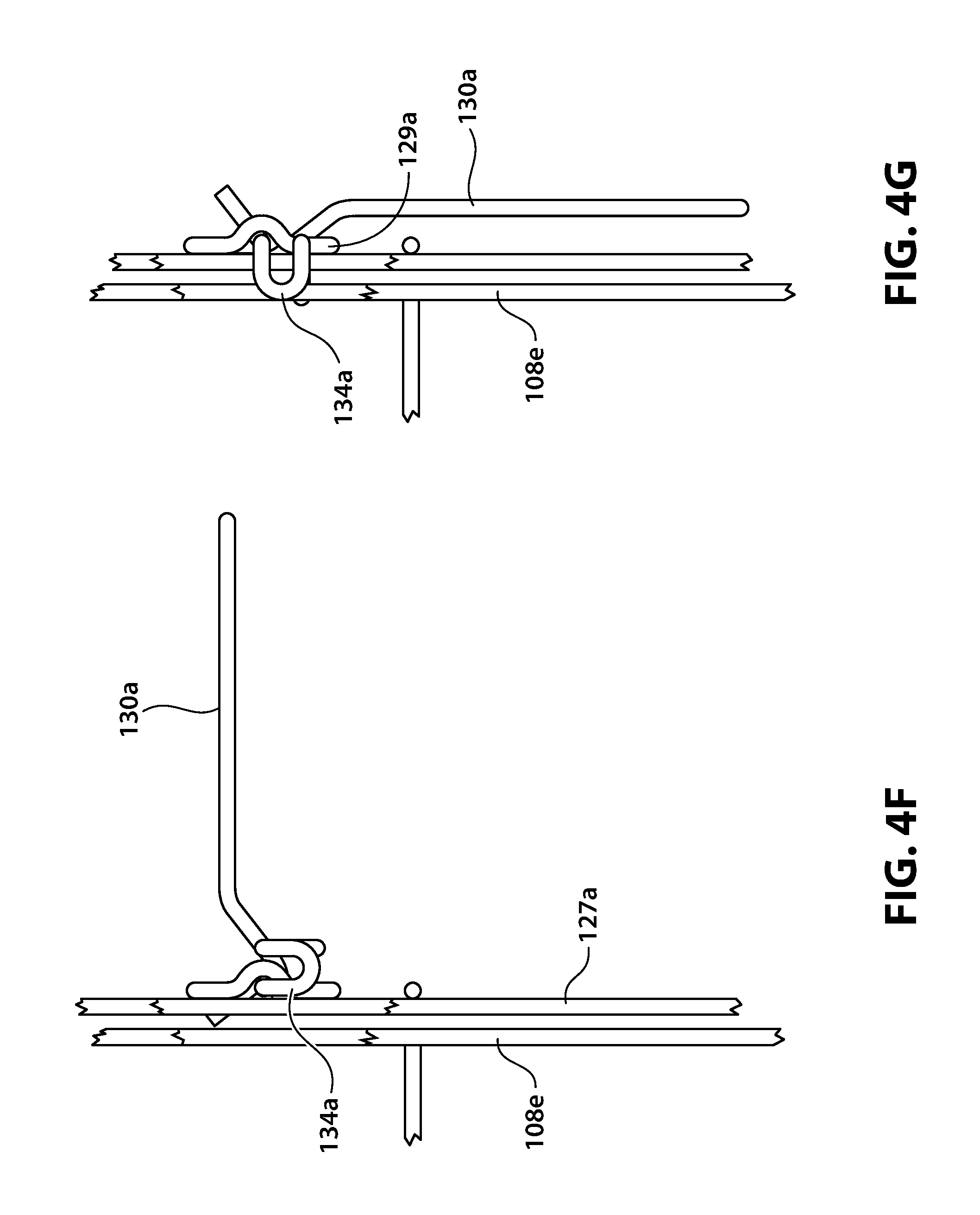
D00015

D00016

D00017

D00018

D00019

D00020
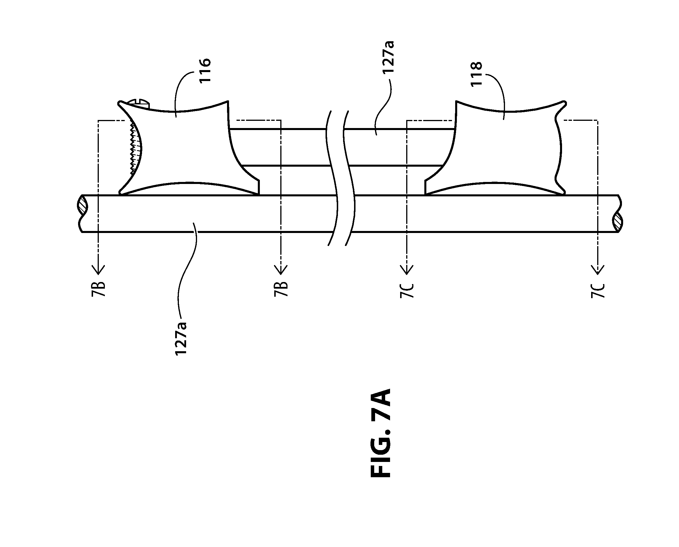
D00021
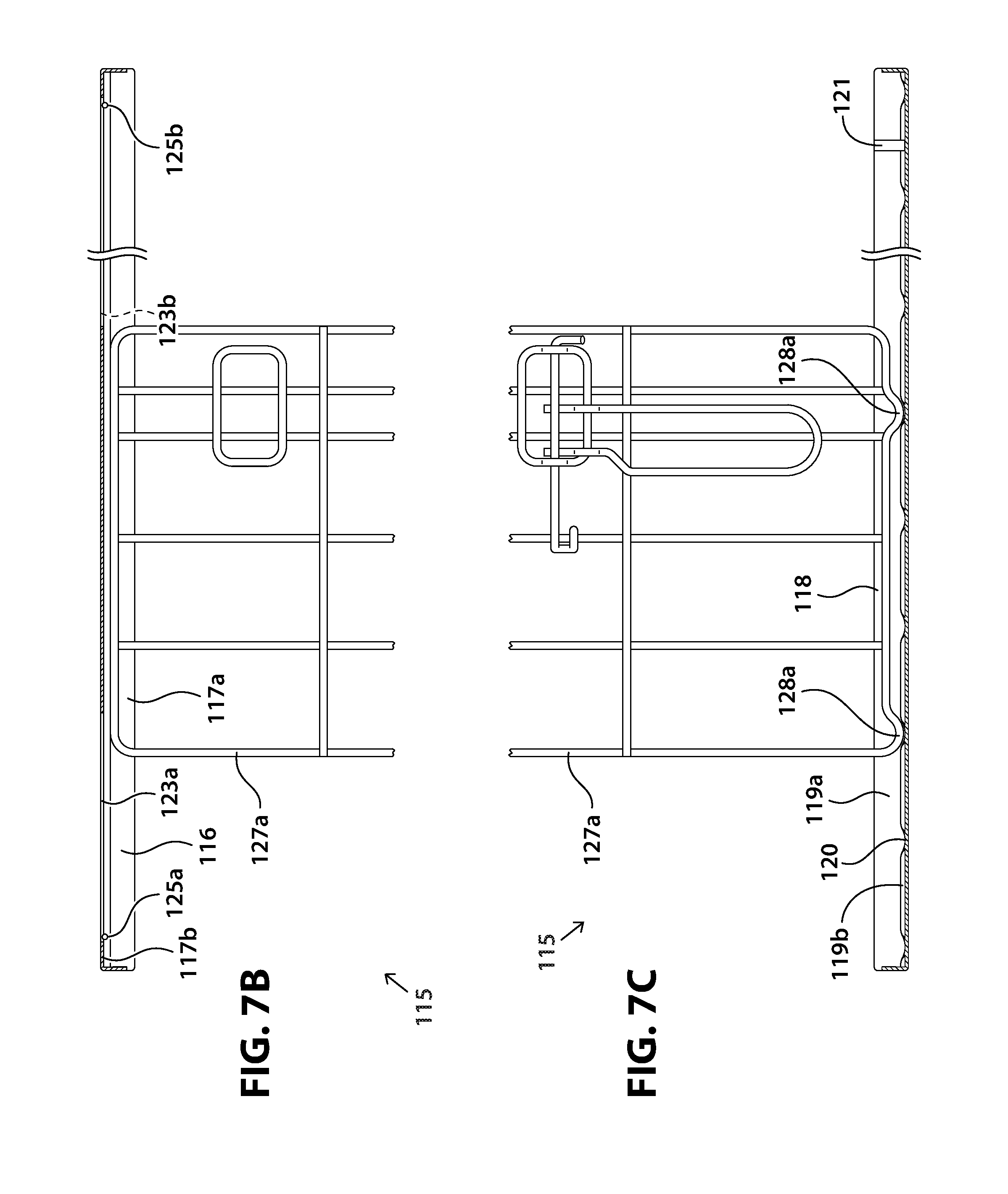
D00022

D00023

D00024

D00025
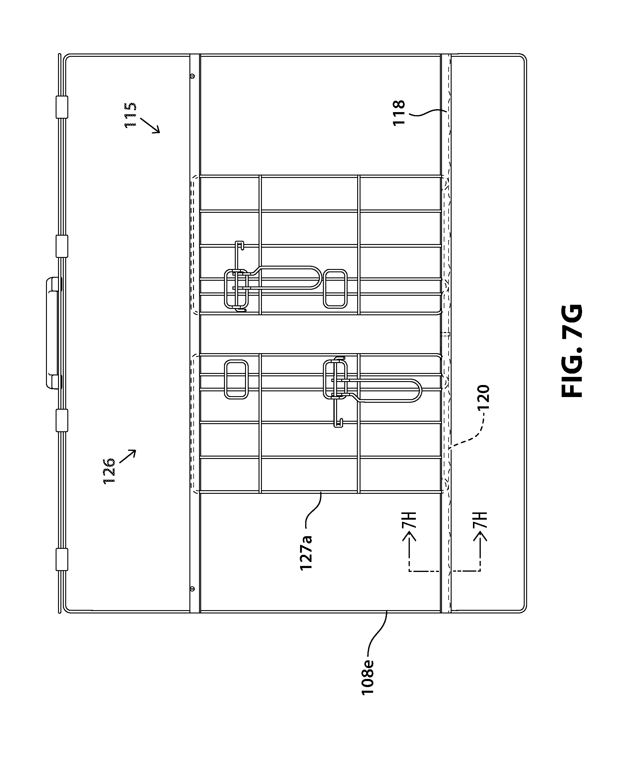
D00026

D00027
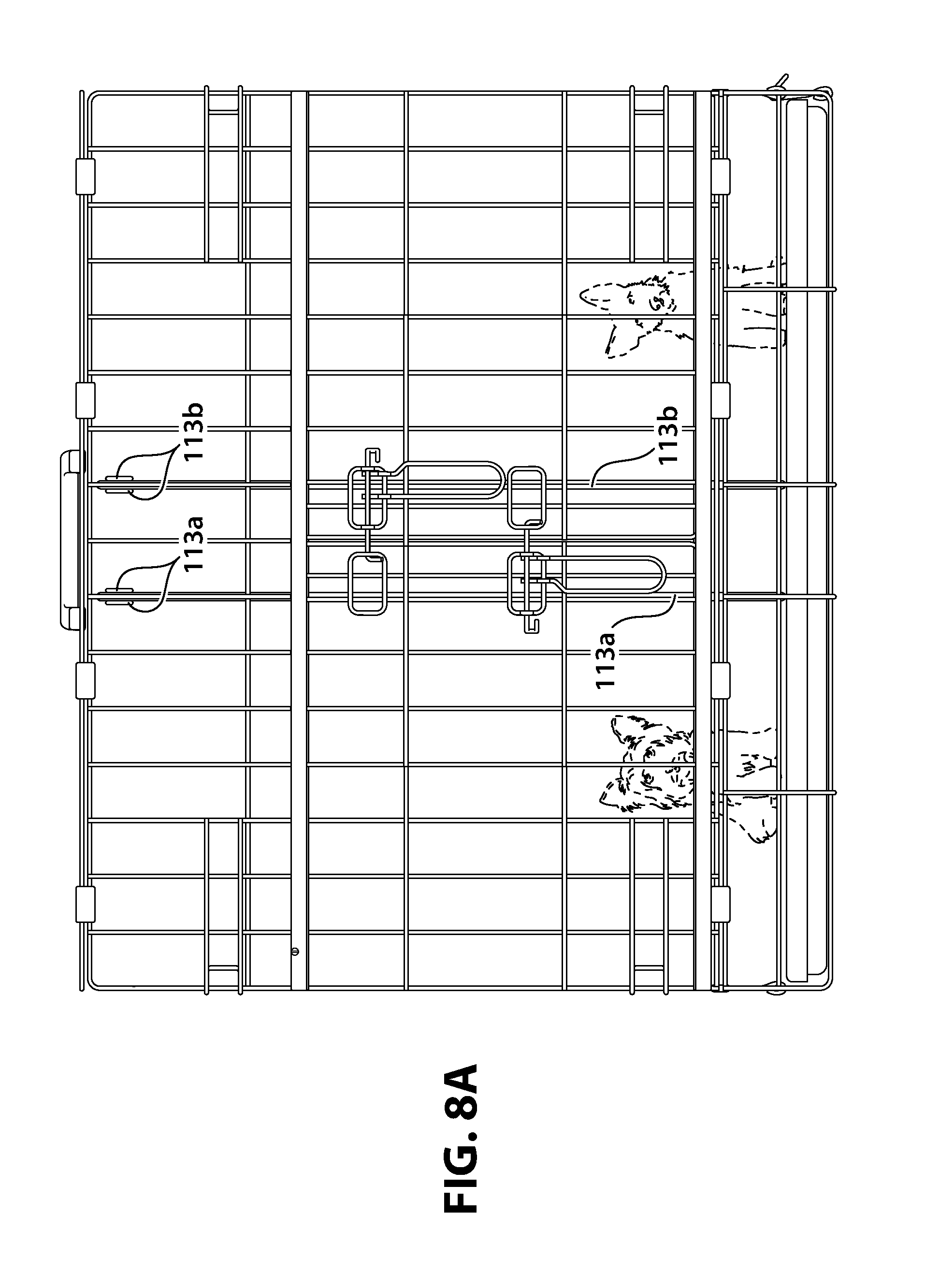
D00028
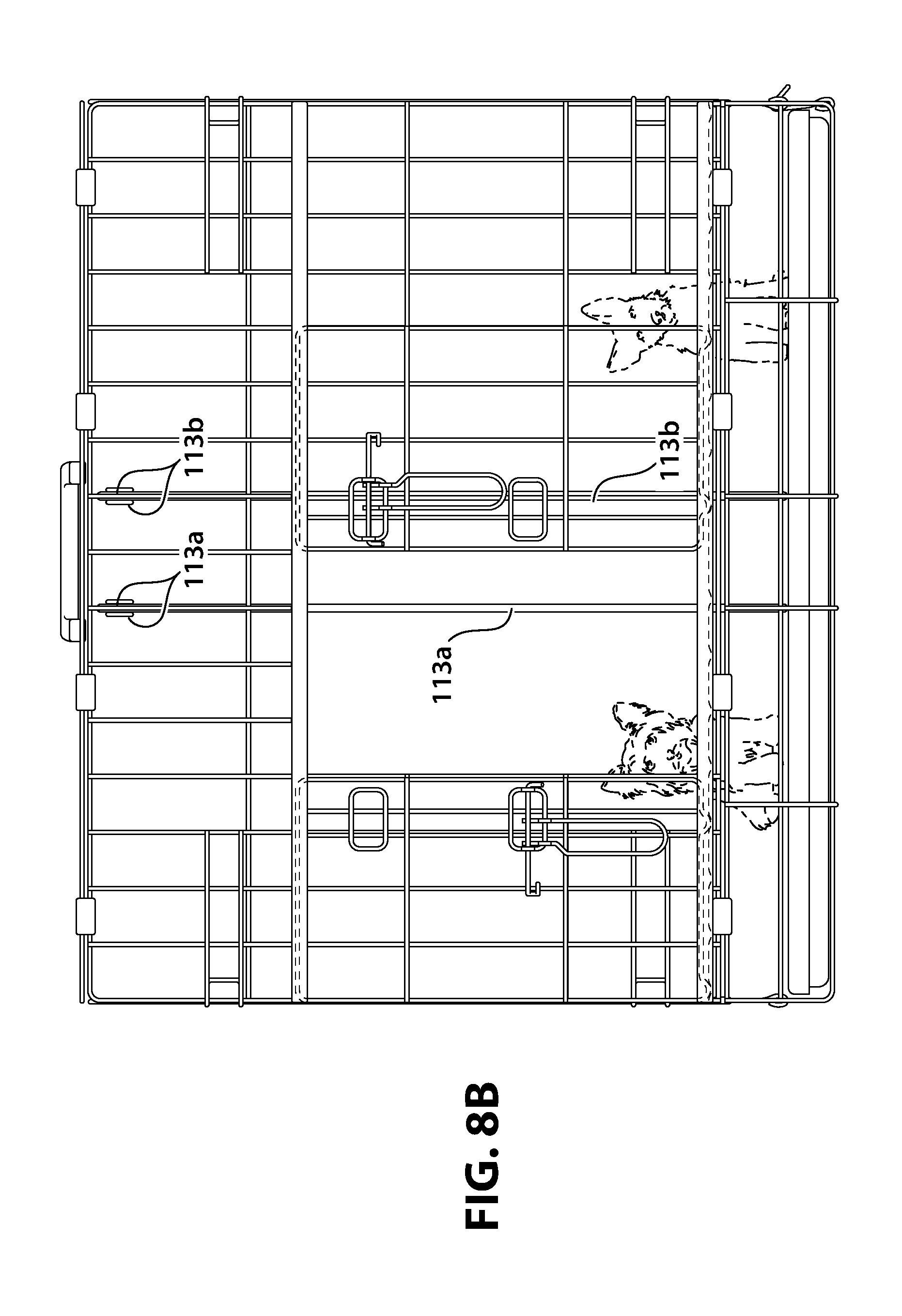
D00029

D00030
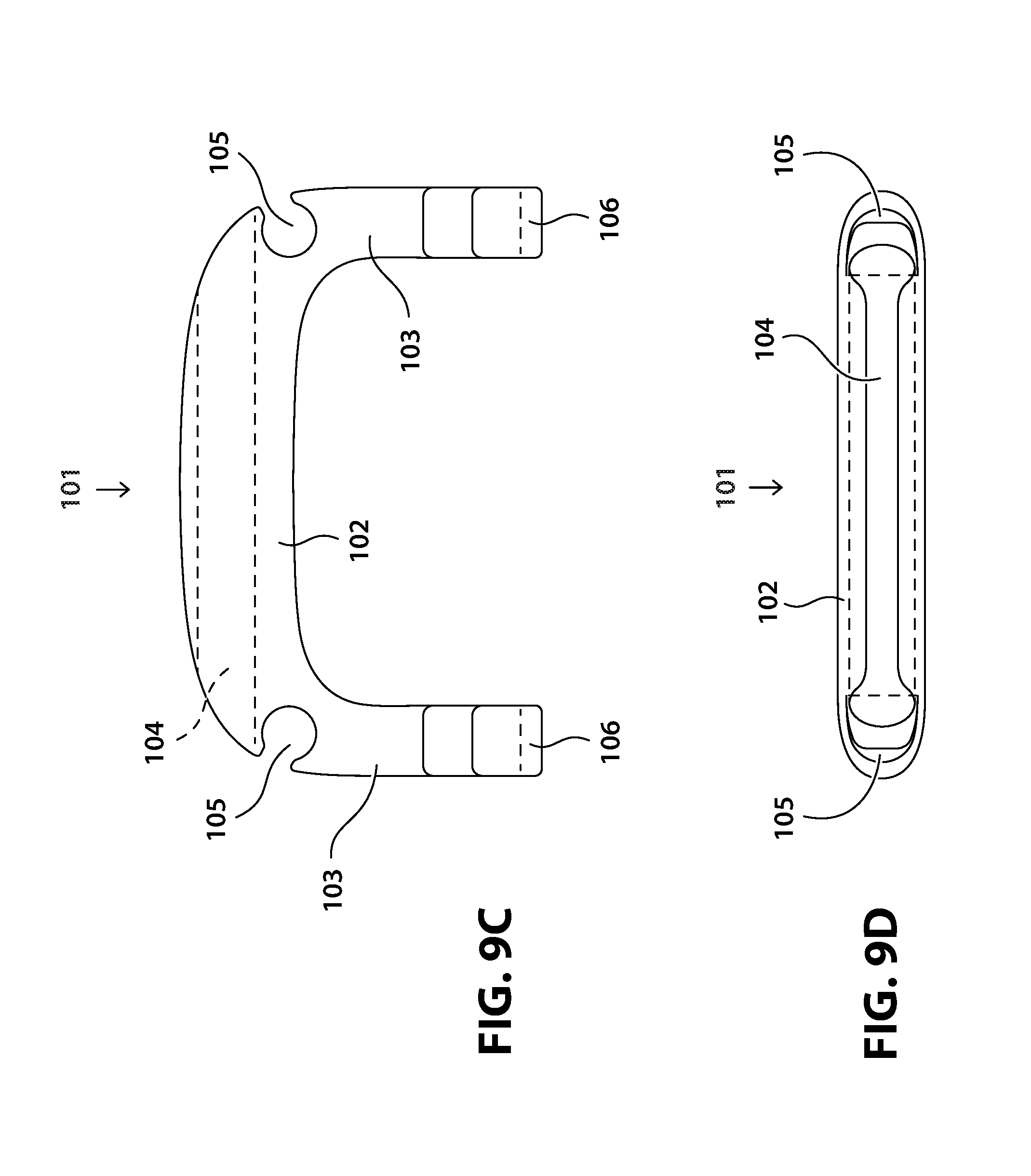
D00031

D00032

D00033

D00034

D00035

D00036

D00037

D00038

D00039

D00040
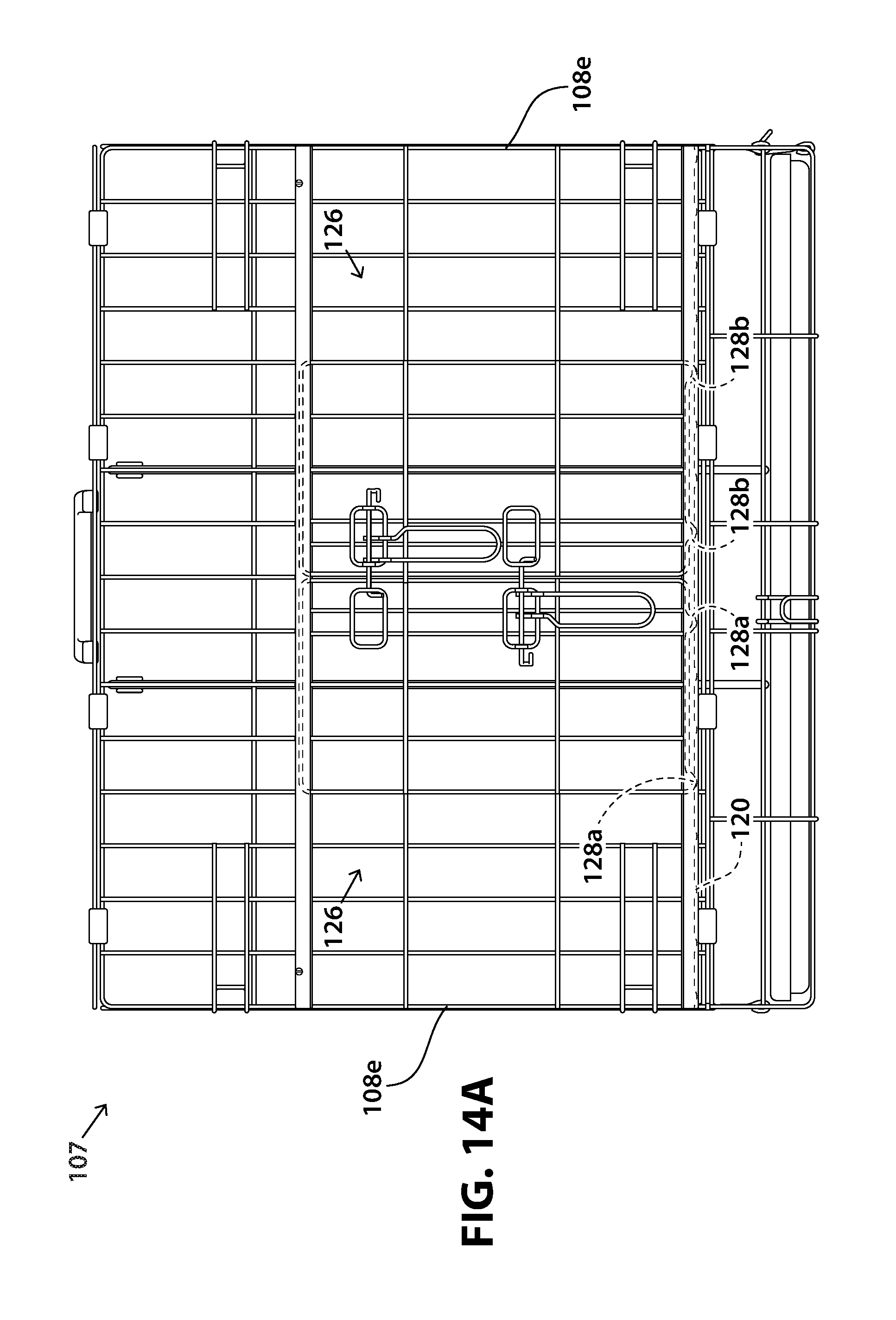
D00041

D00042
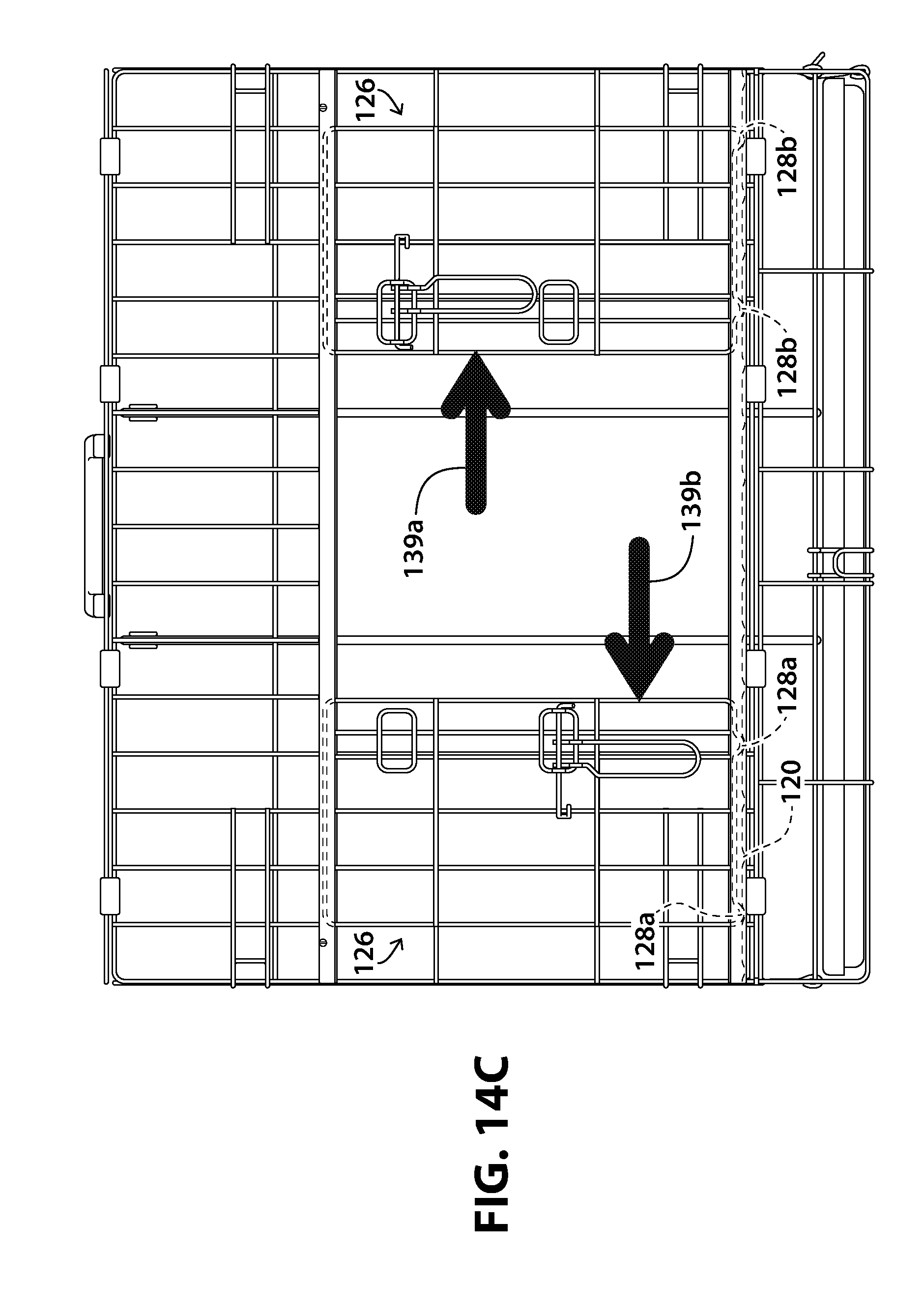
D00043

D00044

D00045

D00046

D00047
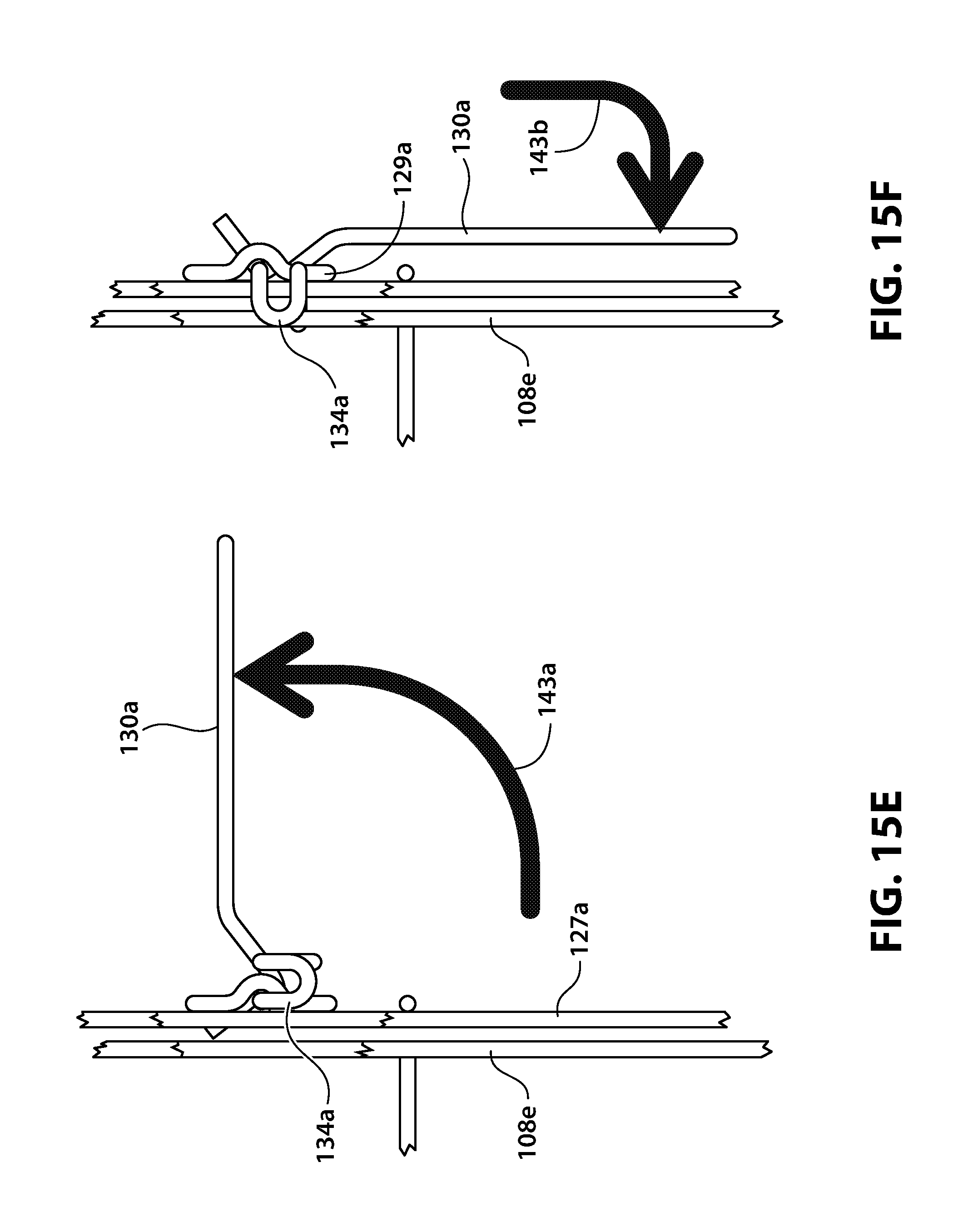
D00048

D00049

D00050

D00051

D00052
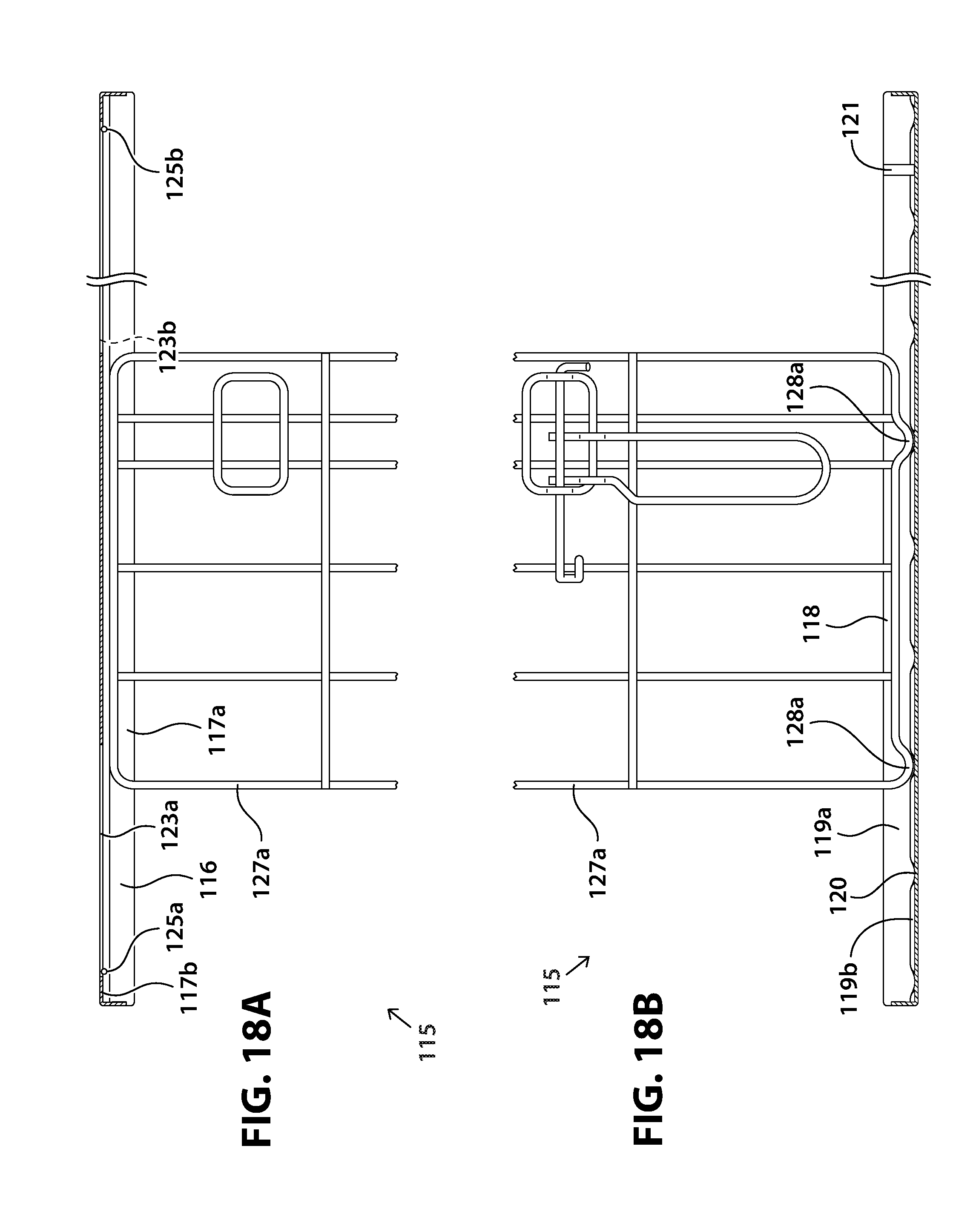
D00053

D00054

D00055

D00056

D00057

D00058
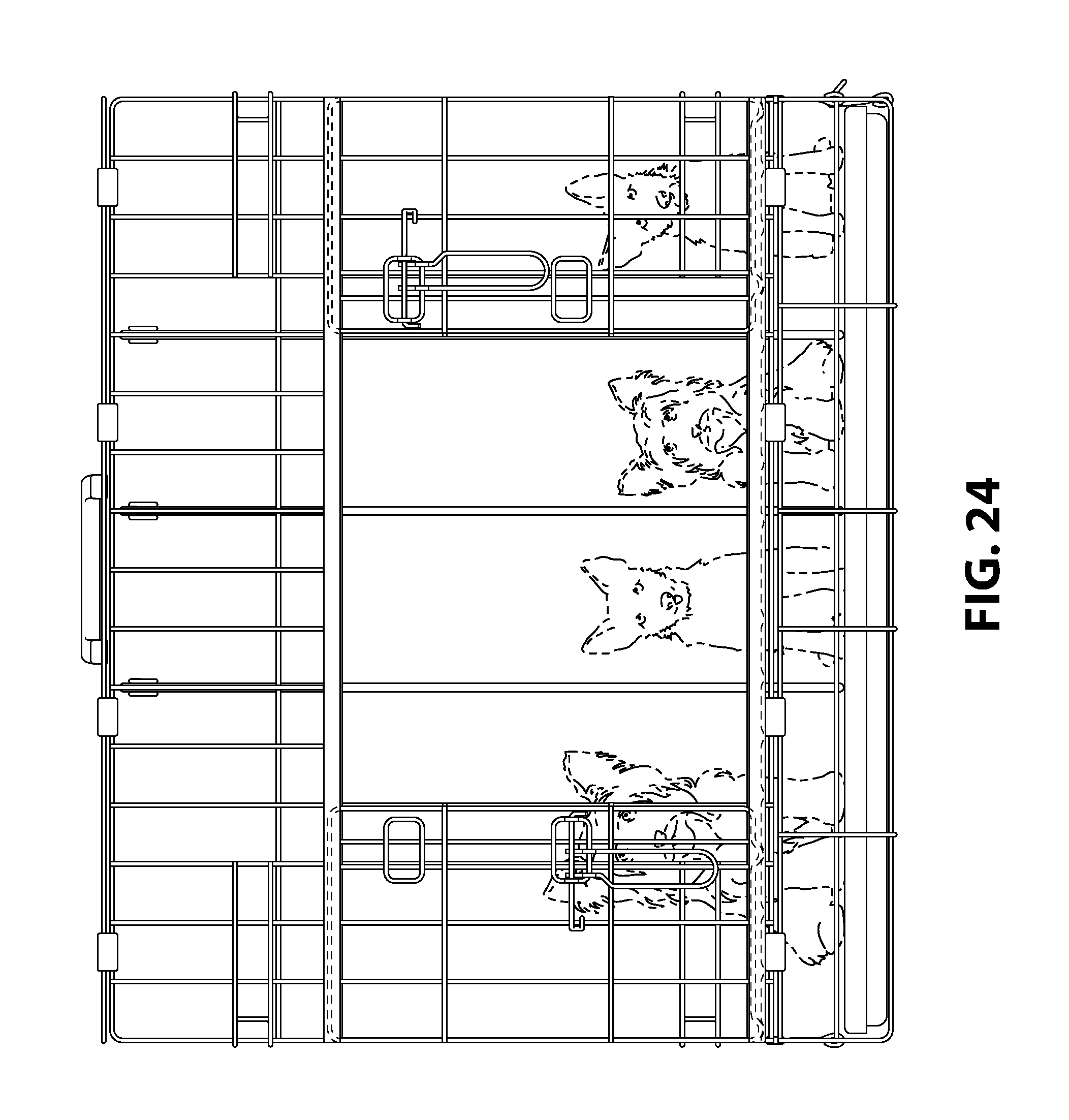
D00059

D00060

D00061

D00062

XML
uspto.report is an independent third-party trademark research tool that is not affiliated, endorsed, or sponsored by the United States Patent and Trademark Office (USPTO) or any other governmental organization. The information provided by uspto.report is based on publicly available data at the time of writing and is intended for informational purposes only.
While we strive to provide accurate and up-to-date information, we do not guarantee the accuracy, completeness, reliability, or suitability of the information displayed on this site. The use of this site is at your own risk. Any reliance you place on such information is therefore strictly at your own risk.
All official trademark data, including owner information, should be verified by visiting the official USPTO website at www.uspto.gov. This site is not intended to replace professional legal advice and should not be used as a substitute for consulting with a legal professional who is knowledgeable about trademark law.