Robotic Surgical Devices, Systems and Related Methods
Farritor; Shane ; et al.
U.S. patent application number 16/123619 was filed with the patent office on 2019-01-24 for robotic surgical devices, systems and related methods. The applicant listed for this patent is Shane Farritor, Amy Lehman, Eric Markvicka, Ryan McCormick, Dmitry Oleynikov, Kyle Strabala, Tyler Wortman. Invention is credited to Shane Farritor, Amy Lehman, Eric Markvicka, Ryan McCormick, Dmitry Oleynikov, Kyle Strabala, Tyler Wortman.
| Application Number | 20190028326 16/123619 |
| Document ID | / |
| Family ID | 47506501 |
| Filed Date | 2019-01-24 |


View All Diagrams
| United States Patent Application | 20190028326 |
| Kind Code | A1 |
| Farritor; Shane ; et al. | January 24, 2019 |
Robotic Surgical Devices, Systems and Related Methods
Abstract
Disclosed herein are various medical devices and related systems, including robotic and/or in vivo medical devices. Also disclosed are various robotic surgical devices for in vivo medical procedures. Included herein, for example, is a robotic surgical system having a support beam positionable through an incision, and a robotic device having a device body, first and second rotating shoulder components coupled to the device body, and first and second robotic arms coupled to the first and second shoulder components, respectively.
| Inventors: | Farritor; Shane; (Lincoln, NE) ; Wortman; Tyler; (Grand Island, NE) ; Strabala; Kyle; (Pittsburgh, PA) ; McCormick; Ryan; (Arlington, VA) ; Lehman; Amy; (York, NE) ; Oleynikov; Dmitry; (Omaha, NE) ; Markvicka; Eric; (Brush, CO) | ||||||||||
| Applicant: |
|
||||||||||
|---|---|---|---|---|---|---|---|---|---|---|---|
| Family ID: | 47506501 | ||||||||||
| Appl. No.: | 16/123619 | ||||||||||
| Filed: | September 6, 2018 |
Related U.S. Patent Documents
| Application Number | Filing Date | Patent Number | ||
|---|---|---|---|---|
| 14800423 | Jul 15, 2015 | 10111711 | ||
| 16123619 | ||||
| 13546831 | Jul 11, 2012 | 9089353 | ||
| 14800423 | ||||
| 61506384 | Jul 11, 2011 | |||
| Current U.S. Class: | 1/1 |
| Current CPC Class: | H04L 43/08 20130101; A61B 90/361 20160201; H04L 41/0631 20130101; B25J 9/0087 20130101; G05B 2219/40418 20130101; B25J 9/06 20130101; Y10S 901/02 20130101; A61B 34/30 20160201; A61B 90/30 20160201; Y10S 901/19 20130101; A61B 2034/302 20160201 |
| International Class: | H04L 12/24 20060101 H04L012/24; H04L 12/26 20060101 H04L012/26 |
Goverment Interests
GOVERNMENT SUPPORT
[0002] This invention was made with government support under Grant No. W81XWH-08-2-0043 awarded by the U.S. Army Medical Research and Materiel Command within the Department of Defense; Grant No. NNX10AJ26G awarded by the National Aeronautics and Space Administration; and Grant No. DGE-1041000 awarded by the National Science Foundation. The government has certain rights in the invention.
Claims
1. (canceled)
2. A robotic surgical device comprising: (a) an elongate support beam configured to be positionable through a port into a body cavity of a patient such that a distal portion of the elongate support beam is positioned within the body cavity and a proximal portion of the elongate support beam is positioned outside the body cavity; (b) a body component operably coupled to a distal end of the support beam; (c) a first rotating shoulder component rotatably coupled to the body component; (d) a second rotating shoulder component rotatably coupled to the body component; (e) a first movable segmented robotic arm operably coupled to the first shoulder component, the first movable segmented robotic arm comprising: (i) a first operational component operably coupled to the first movable segmented robotic arm; and (ii) at least one first arm motor associated with the first movable segmented robotic arm; and (f) a second movable segmented robotic arm operably coupled to the second shoulder component, the second movable segmented robotic arm comprising: (i) a second operational component operably coupled to the second movable segmented robotic arm; and (ii) at least one second arm motor associated with the second movable segmented robotic arm.
3. The robotic surgical device of claim 2, wherein the robotic device may be assembled within the body cavity of the patient.
4. The robotic surgical device of claim 1, further comprising a first support rod disposed through a first lumen in the support beam and operably coupled at a distal end of the first support rod with the body component.
5. The robotic surgical device of claim 4, further comprising a second support rod disposed through a second lumen in the support beam and operably coupled at a distal end of the second support rod with the body component.
6. The robotic surgical device of claim 5, wherein the elongate support beam further comprises a third lumen configured to receive at least one connection component.
7. The robotic surgical device of claim 2, wherein the first operational component is chosen from a group consisting of a grasping component, a cauterizing component, a suturing component, an imaging component, an operational arm component, a sensor component, and a lighting component.
8. The robotic surgical device of claim 2, wherein the second operational component is chosen from a group consisting of a grasping component, a cauterizing component, a suturing component, an imaging component, an operational arm component, a sensor component, and a lighting component.
9. The robotic surgical device of claim 2, wherein the at least one first arm motor is configured for operation, rotation or movement of at least one of the first shoulder, the first segmented arm, and the first operational component.
10. The robotic surgical device of claim 2, wherein the at least one second arm motor is configured for operation, rotation or movement of at least one of the second shoulder, the second segmented arm, and the second operational component.
11. The robotic surgical device of claim 2, wherein the first and second operational components are rotatable relative to the first and second segmented arms.
12. The robotic surgical device of claim 2, wherein the first and second segmented arms are capable of jointed movement.
13. A method of performing minimally invasive surgery on a patient, the method comprising: a) providing a robotic surgical system comprising: i) a robotic device comprising: A) a body; B) a first robotic arm; C) a first shoulder joint disposed between the body and the first robotic arm; D) a first operational component operably coupled with the first arm; E) a second robotic arm; F) a second shoulder joint disposed between the body and the second robotic arm; G) a second operational component operably coupled with the second arm; and H) at least one motor housed within the robotic device; ii) an elongate support beam operably coupleable at a distal end to the body; b) inserting the robotic device into the cavity of the patient in an at least partially unassembled state through a port positioned within an incision in fluid communication with the cavity of the patient; c) assembling the robotic device inside the cavity of the patient; d) positioning the elongate support beam through the port such that a distal portion of the elongate support beam is disposed within the cavity and a proximal portion of the elongate support beam is disposed outside of the cavity; e) coupling a distal end of the elongate support beam to the body of the device; and f) performing a procedure with the robotic device supported by the elongate support beam and disposed entirely within the cavity of the patient.
14. A robotic surgical system, comprising: a) a support beam configured to be positionable through a port positioned within an incision in fluid communication with a cavity of a patient such that a distal portion of the support beam is disposed within the cavity and a proximal portion of the support beam is disposed outside the cavity; and b) a robotic device sized to be positionable completely within the cavity of the patient, the device comprising: i) a device body coupleable to a distal end of the support beam; ii) a first rotating shoulder component operably coupled to the device body; iii) a first robotic arm operably coupled to the first shoulder component; iv) a first operational component operably coupled to the first robotic arm; v) a second rotating shoulder component operably coupled to the device body; vi) a second robotic arm operably coupled to the second shoulder component; vii) a second operational component operably coupled to the second robotic arm; and viii) at least one actuator housed within the robotic device.
15. The robotic surgical system of claim 14, wherein the at least one actuator is capable of operation, rotation or movement of at least one of the first shoulder, the second shoulder, the first robotic arm, the second robotic arm, the first operational component, and the second operational component.
16. The robotic surgical system of claim 14, wherein the at least one actuator is housed within the group consisting of the device body, the first rotating shoulder component, the second rotating shoulder component, the first robotic arm, the second robotic arm, the first operational component, and the second operational component.
17. The robotic surgical system of claim 14, wherein each of the first and second operational components are chosen from a group consisting of a grasping component, a cauterizing component, a suturing component, an imaging component, an operational arm component, a sensor component, and a lighting component.
18. The robotic surgical system of claim 14, wherein the first and second robotic arms are capable of jointed movement.
19. The robotic surgical system of claim 14, wherein the robotic device is assembleable within the body cavity of the patient.
20. The robotic surgical system of claim 14, further comprising: (a) at least two lumens defined in the support beam; (b) a first support rod disposed within one of the at least two lumens; and (c) a first connection component disposed within another of the at least two lumens of the support beam, the first connection component being operably coupled at a distal end to the device body.
21. The robotic surgical system of claim 20, further comprising an external controller configured to be positioned outside the cavity of the patient, the external controller being operably coupled to the robotic device via the first connection component.
Description
CROSS REFERENCE TO RELATED APPLICATIONS
[0001] This application claims priority as a continuation to U.S. patent application Ser. No. 14/800,423, filed Jul. 15, 2015 and entitled "Robotic Surgical Devices, Systems, and Related Methods;" which claims priority as a continuation to U.S. Pat. No. 9,089,353, issued Jul. 28, 2015 and entitled "Robotic Surgical Devices, Systems and Related Methods," which claims priority to U.S. Patent Application 61/506,384, filed Jul. 11, 2011, and entitled "Robotic Surgical Devices, Systems and Related Methods," all of which are hereby incorporated herein by reference in their entireties.
TECHNICAL FIELD
[0003] The embodiments disclosed herein relate to various medical devices and related components, including robotic and/or in vivo medical devices and related components. Certain embodiments include various robotic medical devices, including robotic devices that are disposed within a body cavity and positioned using a support component disposed through an orifice or opening in the body cavity. Further embodiments relate to methods of operating the above devices.
BACKGROUND
[0004] Invasive surgical procedures are essential for addressing various medical conditions. When possible, minimally invasive procedures such as laparoscopy are preferred. However, known minimally invasive technologies such as laparoscopy are limited in scope and complexity due in part to 1) mobility restrictions resulting from using rigid tools inserted through access ports, and 2) limited visual feedback. Known robotic systems such as the da Vinci.RTM. Surgical System (available from Intuitive Surgical, Inc., located in Sunnyvale, Calif.) are also restricted by the access ports, as well as having the additional disadvantages of being very large, very expensive, unavailable in most hospitals, and having limited sensory and mobility capabilities.
[0005] There is a need in the art for improved surgical methods, systems, and devices.
BRIEF DESCRIPTION OF THE DRAWINGS
[0006] FIG. 1 is a diagram showing a system including a robotic device in use inside a body.
[0007] FIG. 2A is a perspective view of a modular medical device within a body cavity, according to another embodiment.
[0008] FIG. 2B is a perspective view of the modular device of FIG. 2A in a different position.
[0009] FIG. 2C is a perspective close-up view of a portion of the device of FIG. 2A.
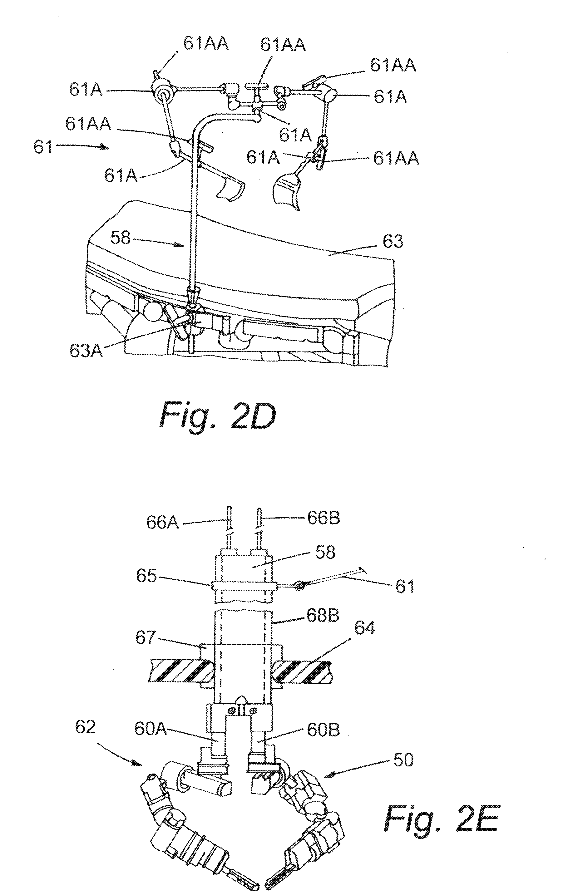
[0010] FIG. 2D is an image of an iron intern used to support the device of FIG. 1A.
[0011] FIG. 2E is a perspective close-up view of a portion of the iron intern of FIG. 2D supporting the device of FIG. 2A.
[0012] FIG. 3A is a perspective view of a modular medical device, according to another embodiment.
[0013] FIG. 3B is a cutaway close-up view of a portion of the device of FIG. 3A.
[0014] FIG. 3C is a cutaway close-up view of a portion of the device of FIG. 3A.
[0015] FIG. 3D is a cutaway close-up view of a portion of the device of FIG. 3A.
[0016] FIG. 3E is a cutaway close-up view of a portion of the device of FIG. 3A.
[0017] FIG. 3F is a cutaway close-up view of a portion of the device of FIG. 3A.
[0018] FIG. 3G is a cutaway perspective view of a portion of the device of FIG. 3A.
[0019] FIG. 3H is a cutaway perspective view of a portion of the device of FIG. 3A.
[0020] FIG. 3I is a cutaway close-up view of a portion of the device of FIG. 3A.
[0021] FIG. 3J is a cutaway close-up view of a portion of the device of FIG. 3A.
[0022] FIG. 3K is a cutaway close-up view of a portion of the device of FIG. 3A.
[0023] FIG. 4A is a perspective view of a modular medical device, according to another embodiment.
[0024] FIG. 4B is a cutaway close-up view of a portion of the device of FIG. 4A.
[0025] FIG. 4C is a cutaway close-up view of a portion of the device of FIG. 4A.
[0026] FIG. 4D is a cutaway close-up view of a portion of the device of FIG. 4A.
[0027] FIG. 4E is a perspective view of a portion of the device of FIG. 4A.
[0028] FIG. 4F is a perspective view of a modular medical device, according to another embodiment.
[0029] FIG. 4G is a close-up view of a modular medical device according to another embodiment.
[0030] FIG. 5A is a perspective view of a modular medical device, according to another embodiment.
[0031] FIG. 5B is a cutaway close-up front view of a portion of the device of FIG. 5A.
[0032] FIG. 5C is a cutaway close-up front view of a portion of the device of FIG. 5A.
[0033] FIG. 5D is a cutaway top view of a portion of the device of FIG. 5A.
[0034] FIG. 5E is a perspective close-up view of a portion of the device of FIG. 5A.
[0035] FIG. 5F is a cutaway close-up front view of a portion of the device of FIG. 5A.
[0036] FIG. 5G is a cutaway close-up side view of a portion of the device of FIG. 5A.
[0037] FIG. 5H is a cutaway close-up top view of a portion of the device of FIG. 5A.
[0038] FIG. 5I is a cutaway close-up side view of a portion of the device of FIG. 5A.
[0039] FIG. 5J is a cutaway close-up side view of a portion of the device of FIG. 5A.
[0040] FIG. 5K is a bottom isometric close-up view of a portion of the device of FIG. 5A.
[0041] FIG. 5L is a cutaway close-up view of a portion of the device of FIG. 5A.
[0042] FIG. 5M is a perspective close-up view of a portion of the device of FIG. 5A.
[0043] FIG. 5N is a cutaway close-up side view of a portion of the device of FIG. 5A.
[0044] FIG. 5O is an isometric interior close-up view of a portion of the device of FIG. 5A.
[0045] FIG. 5P is an isometric interior close-up view of a portion of the device of FIG. 5A.
[0046] FIG. 5Q is an isometric interior close-up view of a portion of the device of FIG. 5A.
[0047] FIG. 5R is an isometric view of a portion of the device of FIG. 5A in one position.
[0048] FIG. 5S is an isometric view of a portion of the device of FIG. 5A in another position.
DETAILED DESCRIPTION
[0049] The various systems and devices disclosed herein relate to devices for use in medical procedures and systems. More specifically, various embodiments relate to various medical devices, including robotic devices and related methods and systems.
[0050] It is understood that the various embodiments of robotic devices and related methods and systems disclosed herein can be incorporated into or used with any other known medical devices, systems, and methods.
[0051] For example, the various embodiments disclosed herein may be incorporated into or used with any of the medical devices and systems disclosed in copending U.S. applications Ser. No. 12/192,779 (filed on Aug. 15, 2008 and entitled "Modular and Cooperative Medical Devices and Related Systems and Methods"), Ser. No. 11/932,441 (filed on Oct. 31, 2007 and entitled "Robot for Surgical Applications"), Ser. No. 11/695,944 (filed on Apr. 3, 2007 and entitled "Robot for Surgical Applications"), Ser. No. 11/947,097 (filed on Nov. 27, 2007 and entitled "Robotic Devices with Agent Delivery Components and Related Methods), Ser. No. 11/932,516 (filed on Oct. 31, 2007 and entitled "Robot for Surgical Applications"), Ser. No. 11/766,683 (filed on Jun. 21, 2007 and entitled "Magnetically Coupleable Robotic Devices and Related Methods"), Ser. No. 11/766,720 (filed on Jun. 21, 2007 and entitled "Magnetically Coupleable Surgical Robotic Devices and Related Methods"), Ser. No. 11/966,741 (filed on Dec. 28, 2007 and entitled "Methods, Systems, and Devices for Surgical Visualization and Device Manipulation"), Ser. No. 12/171,413 (filed on Jul. 11, 2008 and entitled "Methods and Systems of Actuation in Robotic Devices"), 60/956,032 (filed on Aug. 15, 2007), 60/983,445 (filed on Oct. 29, 2007), 60/990,062 (filed on Nov. 26, 2007), 60/990,076 (filed on Nov. 26, 2007), 60/990,086 (filed on Nov. 26, 2007), 60/990,106 (filed on Nov. 26, 2007), 60/990,470 (filed on Nov. 27, 2007), 61/025,346 (filed on Feb. 1, 2008), 61/030,588 (filed on Feb. 22, 2008), 61/030,617 (filed on Feb. 22, 2008), U.S. Pat. No. 8,179,073 (issued May 15, 2011, and entitled "Robotic Devices with Agent Delivery Components and Related Methods"), Ser. No. 12/324,364 (filed Nov. 26, 2008, U.S. Published App. 2009/0171373 and entitled "Multifunctional Operational Component for Robotic Devices"), Ser. No. 13/493,725 (filed Jun. 11, 2012 and entitled "Methods, Systems, and Devices Relating to Surgical End Effectors") , all of which are hereby incorporated herein by reference in their entireties.
[0052] Certain device and system implementations disclosed in the applications listed above can be positioned within a body cavity of a patient in combination with a support component similar to those disclosed herein. An "in vivo device" as used herein means any device that can be positioned, operated, or controlled at least in part by a user while being positioned within a body cavity of a patient, including any device that is coupled to a support component such as a rod or other such component that is disposed through an opening or orifice of the body cavity, also including any device positioned substantially against or adjacent to a wall of a body cavity of a patient, further including any such device that is internally actuated (having no external source of motive force), and additionally including any device that may be used laparoscopically or endoscopically during a surgical procedure. As used herein, the terms "robot," and "robotic device" shall refer to any device that can perform a task either automatically or in response to a command.
[0053] Certain embodiments provide for insertion of the present invention into the cavity while maintaining sufficient insufflation of the cavity. Further embodiments minimize the physical contact of the surgeon or surgical users with the present invention during the insertion process. Other implementations enhance the safety of the insertion process for the patient and the present invention. For example, some embodiments provide visualization of the present invention as it is being inserted into the patient's cavity to ensure that no damaging contact occurs between the system/device and the patient. In addition, certain embodiments allow for minimization of the incision size/length. Further implementations reduce the complexity of the access/insertion procedure and/or the steps required for the procedure. Other embodiments relate to devices that have minimal profiles, minimal size, or are generally minimal in function and appearance to enhance ease of handling and use.
[0054] Certain implementations disclosed herein relate to "combination" or "modular" medical devices that can be assembled in a variety of configurations. For purposes of this application, both "combination device" and "modular device" shall mean any medical device having modular or interchangeable components that can be arranged in a variety of different configurations. The modular components and combination devices disclosed herein also include segmented triangular or quadrangular-shaped combination devices. These devices, which are made up of modular components (also referred to herein as "segments") that are connected to create the triangular or quadrangular configuration, can provide leverage and/or stability during use while also providing for substantial payload space within the device that can be used for larger components or more operational components. As with the various combination devices disclosed and discussed above, according to one embodiment these triangular or quadrangular devices can be positioned inside the body cavity of a patient in the same fashion as those devices discussed and disclosed above.
[0055] FIG. 1 depicts an exemplary system 10 that includes a robotic surgical device 12 disposed within the inflated peritoneal cavity 14 of a patient. It is understood that the various device and system embodiments disclosed herein, including the system 10 of FIG. 1, can be used for a variety of surgical procedures and tasks including, but not limited to, tissue biopsy, tissue dissection, or tissue retraction. For example, as shown in FIG. 1 in accordance with one embodiment, the device 12 can be used to dissect tissue in the peritoneal cavity 14. In this system 10 embodiment, a user (such as, for example, a surgeon) operates a user interface 16 to control the device 12. The interface 16 is operably coupled to the device 12 by a cable 18 or other type of physical connection that provides for electronic and/or electrical communication back and forth between the interface 16 and the device 12. Alternatively, the interface 16 can be operably coupled to the device 12 wirelessly. It is understood that the device embodiments disclosed herein can also be used with any other known system, including any of the systems disclosed in the various patent applications incorporated by reference above and elsewhere herein.
[0056] FIGS. 2A-2C depict a robotic medical device 50 positioned within a patient's body cavity 62, in accordance with one implementation. According to one embodiment, the device 50 is an in vivo device 50. This device embodiment 50 as shown includes a body 52 that has two components 52A, 52B, which in this embodiment are cylindrical components 52A, 52B. In the embodiment depicted in FIG. 2C, the two components 52A, 52B are not coupled directly to each other. Alternatively, the two components 52A, 52B can be coupled to each other. In a further alternative, the body 52 (and any body of any device embodiment disclosed herein) can be a single component and further can be any of the device body embodiments disclosed in the various patent applications incorporated by reference above and elsewhere herein.
[0057] The body 52 is coupled to two arms 54, 56. In the implementation shown, the body component 52A is coupled to arm 54 and body component 52B is coupled to arm 56. In addition, the body 52 is also coupled to a support component 58. In this embodiment, the support component 58 is configured to be positioned over two support rods 66A, 66B as best shown in FIGS. 2A and 2B. The component 58 also has a first support leg 60A that is coupled to the first body component 52A and a second support leg 60B that is coupled to the second body component 52B. Alternatively, the support component 58 can be a single, integral component coupled to the body 52.
[0058] Each of the arms 54, 56 have a first joint 54A, 56A (each of which can also be referred to as a "shoulder joint") that is coupled to the body components 52A, 52B. Each first joint 54A, 56A is coupled to a first link 54B, 56B that is rotatably coupled to a second link 54C, 56C. In addition, each arm 54, 56 also has an operational component 54D, 56D coupled to the second link 54C, 56C. It is understood that the operational components 54D, 56D (and any of the operational components on any of the embodiments disclosed herein) can be any known operational components, including any of the operational components disclosed in the various patent applications incorporated by reference above and elsewhere herein.
[0059] As mentioned above, the first links 54B, 56B are coupled to the body 52 via shoulder joints 54A, 56A. As shown, each shoulder joint 54A, 56A is a joint having two axes of rotation. For example, joint 54A can rotate as shown by arrow A around axis AA that corresponds to the longitudinal axis of the body 52 while also being coupled to the first link 54B such that the link 54B can further rotate as shown by arrow B around axis BB that is perpendicular to axis AA that corresponds to the longitudinal axis of the body 52. Joint 56A has similar axes of rotation. Alternatively, any known joint can be used to couple the first links 54B, 56B to the body 52.
[0060] The operational components 54D, 56D, according to one implementation, are coupled to the second links 54C, 56C, respectively, such that each of the operational components 54D, 56D can rotate. For example, operational component 54D can rotate as shown by arrow C around axis CC corresponding to the longitudinal axis of the link 54C to which the component 54D is attached. Operational component 56D can rotate in a similar fashion. In addition, each of the operational components 54D, 56D can also be actuated to move between at least two configurations, such as an open configuration and a closed configuration. Alternatively, the operational components 54D, 56D can be coupled to the links 54C, 56C such that the operation components can be moved or actuated in any known fashion.
[0061] According to one embodiment, the operational components 54D, 56D are also removable from the second links 54C, 56C, such that the components 54D, 56D are interchangeable with other components configured to perform other/different types of procedures. In the embodiment depicted in FIG. 2C, both operational components 54D, 56D are graspers. Alternatively, either or both of the components can be cautery devices, suturing devices, grasping devices, imaging devices, operational arm devices, sensor devices, lighting devices or any other known types of devices or components for use in surgical procedures.
[0062] It is understood that the device 50 in this embodiment contains the motors (also referred to as "actuators," and intended to include any known source of motive force) that provide the motive force required to move the arms 54, 56 and the operational components 54D, 56D. In other words, the motors are contained within the device 50 itself (either in the body 52, the arms 54, 56 or both), rather than being located outside the patient's body.
[0063] In use, as best shown in FIGS. 2A and 2B, the device 50 is positioned inside a patient's body cavity. For example, in the schematic depict of FIGS. 2A and 2B, the body cavity is the peritoneal cavity 62. According to one implementation, the device 50 can be inserted through a single orifice by physically separating the device 50 into separate, smaller components and inserting those components through the single orifice. In one example, the device 50 can be separated into two "halves," in which one component consists of the first body component 52A coupled to the first arm 54 and the other component consists of the second body component 52B coupled to the second arm 56. Alternatively, this device 50 or any device contemplated herein can be separated into any two or more separable components. In the embodiment depicted in FIG. 2C, the device 50 is first separated into the two components as described above and then each of the two components are inserted in consecutive fashion through the orifice into the body cavity. In accordance with one implementation, due to the limitations associated with the amount of space in the cavity, each of the components can form a sequence of various configurations that make it possible to insert each such component into the cavity. That is, each component can be "stepped through" a sequence of configurations that allow the component to be inserted through the orifice and into the cavity.
[0064] According to one embodiment as best shown in FIGS. 2A and 2B, the support component 58 (including the support rods 66A, 66B) is configured to maintain the device 50 in the desired positioned within the cavity 62. The component 58, which is coupled to the body 52, is disposed through an orifice or any other kind of opening in the body cavity wall 64 such that the distal portion of the component 58 coupled to the body 52 is disposed within the body cavity 62 while the proximal portion is disposed outside of the patient's body and is attached to an external component 61 so as to provide stability or fixed positioning for the device 50.
[0065] More specifically, the two support rods 66A, 66B are coupled to the device 50. That is, the first support rod 66A is coupled to the first body component 52A and the second support rod 66B is coupled to the second body component 52B. Alternatively, the body 52 can be a single component and is coupled to both support rods 66A, 66B. As discussed above, this embodiment also has a support component 58 that is disposed over the support rods 66A, 66B (or alternatively, the support rods 66A, 66B are disposed within the support component 58) and positioned against or coupled to the body 52. As best shown in FIG. 2E, the component 58 defines two lumens 68A, 68B that are disposed through the length of the tube component 58. In some embodiments, an access lumen (not shown) is disposed through a substantially central or middle portion of the component 58, with the two rod lumens 68A, 68B disposed on either side of the access lumen. The rod lumens 68A, 68B are configured to receive the support rods 66A, 66B such that the component 58 can be positioned over the support rods 66A, 66B and against the body 52 of the device. The access lumen is configured to receive and provide access for any tools or endoscopes such that the tools or endoscopes can be inserted through the access lumen and into the body cavity to provide additional functionality in combination with the device 50.
[0066] In this embodiment, the support rods 66A, 66B are held in place within the component 58 (or the component 58 is held in place over the support rods 66A, 66B) using two attachment components 72A, 72B, each of which is configured to attach to one of the support rods 66A, 66B, as shown in FIG. 2A. In the specific embodiment shown in FIG. 2A, the attachment components 72A, 72B are threaded nuts, and after the support component 58 is disposed over the two support rods 66A, 66B, the threaded nut 72A is threadably coupled to the support rod 66A and the wing nut 72B is threadably coupled to the support rod 66B to hold the component 58 in place. Alternatively, the attachment components 72A, 72B can be any known attachment components for holding the component 58 in place.
[0067] FIGS. 2D-2E depict an external component 61 and port 67 that support device 50 while positioned within a patient's body cavity 62, in accordance with one implementation. According to this implementation, the device 50 is maintained in a desired position or location within the body cavity of the patient using an external component 61 that has a clamp 65 that is removably attached to support component 58. In use, the support legs 60A, 60B and the support component 58 are disposed through an opening in the body cavity wall such that the distal end of the legs 60A, 60B and the distal end of the support component 58 are positioned within the body cavity while the proximal end of the legs 60A, 60B and support component 58 are disposed outside of the patient's body. The external component 61 is coupleable to a proximal portion of the support component 58. In this embodiment, the clamp 65 couples to support component 58 to hold the support component 58 and thus the legs 60A, 60B and device 50 in the desired position. Alternatively, the external component 61 can have any known attachment component that is capable of removably coupling to or attaching to support component 58 and support legs 60A, 60B.
[0068] As best shown in FIG. 2D, an external component 61 can be an iron intern (Automated Medical Products Corp.) that includes several sections connected by joints 61A that can be loosened and locked using knobs 61AA to allow the iron intern to be positioned in various orientations. The external component 61 can be attached to rails 63A on any standard surgical table 63 or any other appropriate surface to provide support for device.
[0069] In use, according to one embodiment as best shown in FIG. 2E, the device 50 is positioned within the body cavity of the patient and the support legs 60A, 60B and support component 58 are positioned through a port 67 positioned in the hole or opening in the body cavity wall 64. In this embodiment, the port 67 is a gel port 67 through which the legs 60A, 60B and support component 58 can be disposed while still maintaining a fluidic seal that allows for the body cavity of the patient to be inflated. Alternatively, any known port that provides access for the legs 60A, 60B and support component 58 while maintaining a fluidic seal can be used. FIGS. 3A-3L depict another embodiment of a robotic medical device 100. This device embodiment 100 as shown includes a body 102 having two cylindrical components 102A, 102B. The device has two arms 106, 108 that are coupled to the body 102. More specifically, the first arm 106 is rotatably coupled to the first cylindrical component 102A and the second arm 108 is rotatably coupled to the second cylindrical component 102B. The first arm 106 has a first link 106A that is coupled to the first component 102A, a second link 106B that is coupled to the first link 106A, and a third link 106C coupled to the second link 106B. Similarly, the second arm 108 has a first link 108A that is coupled to the second component 102B, a second link 108B that is coupled to the first link 108A, and a third link 108C coupled to the second link 108B. The first arm 106 has an operational component 106D coupled to the third link 106C, and the second arm 108 has an operational component 108D coupled to the third link 108C. In addition, the body 102 is also coupled to a support component 105, which is in turn, connected to support rods 103A and 103B.
[0070] The first link 106A is coupled to the first component 102A such that the first link can rotate around an axis parallel to the longitudinal axis of the first component 102A. As best shown in FIG. 3B, first component 102A includes a motor housing 102C that houses motor 101 and actuation mechanism 101A for first joint 101B. In this embodiment, the actuation mechanism 101A includes spur gear 101D that is rigidly attached to output shaft 101C of motor 101. As the motor output shaft 101C turns, spur gear 101D rotates spur gear 107, which is radially constrained with rotational shaft 107A through a flat 107B attached to both 107A and the bore of 107. 107A is supported with two flanged ball bearings 107C and 107D. Flanged ball bearing 107D is seated in the lower cap 102D of housing 102C. Rotational shaft 107A is attached to first link 106A via attachment 110 using, for example, a bolt. First link 108A is similarly coupled to the second component 102B such that the first link can rotate around an axis parallel to the longitudinal axis of the second component 102B.
[0071] The second link 106B is coupled to the first link 106A such that the second link 106B can rotate around an axis parallel to the longitudinal axis of first link 106A. As best shown in FIG. 3C, first link 106A includes motor housing half 109 comprising attachment 110. A second motor housing half (not shown) is configured similarly to motor housing half 109 and attaches to motor housing half 109 via attachment 110 using, for example, bolts to form a complete motor housing for first link 106A. The joint between first link 106A and second link 106B is actuated from a motor 112 located inside the motor housing. Encoder 113 provides position information to the interface (not shown) for motor 112. A planetary gearhead 111 is attached to motor 112 by way of mating threading on the motor 112 and planetary gearhead 111. Gearhead 111 is rigidly attached to gear housing 122 by use of epoxy to prevent rotation and translation of the motor assembly. Spur gear 123 is rigidly attached to the output shaft 111A of gearhead 111. As spur gear 123 is rotated by the motor 112, torque is transmitted to spur gear 115, which is rigidly attached to shaft 116. Shaft 116 is supported by ball bearings 117 and 118, housed in gear housing 122, and attaches to second link 106B. A button socket cap bolt 119 is threaded into shaft 116, preventing lateral translation of shaft 116. The second link 108B is similarly configured and coupled to first link 108A.
[0072] The second link 106B is configured such that, in addition to rotating around an axis parallel to the longitudinal axis of first link 106A, it can rotate around an axis perpendicular to the longitudinal axis of first link 106A. As best shown in FIGS. 3D and 3E, second link 106B comprises mirrored motors 130A and 130B and associated gears and shafts. Motor 130A and its associated gears and shafts are configured to rotate second link 106B in an axis perpendicular to the longitudinal axis of first link 106A. Shaft 116 from first link 106A includes a bore through which rotational shaft 133A of second link 106B inserts and attaches. Rotational shaft 133A and the bore of shaft 116 are constrained such that the rotation of rotational shaft 133A is fixed relative to shaft 116. Ball bearings 136A and 137A, which are housed in the motor housing 134, support rotational shaft 133A. A spur gear 131A is rigidly attached to shaft 133A and bolt 138A constrains rotational shaft 133A axially. Rotational shaft 133A is rotated as motor 130A is actuated, rotating spur gear 132A, which is rigidly attached to output shaft 135A of motor 130A. Motor 130A is constrained relative to housing 134 using, for example, bolts which go through housing 134. Gear cover 139A covers the moving gears to prevent outside objects from contacting the moving gears 131A, 132A.
[0073] The third link 106C is coupled to the second link 106B such that the third link can rotate around an axis perpendicular to the longitudinal axis of second link 106B. Motor 130B and its associated gears and shafts are configured to rotate shaft 140, which attaches to third link 106C, in an axis perpendicular to the longitudinal axis of second link 106B. As best shown in FIG. 3E, motor 130B is configured to actuate its associated gears and shafts in a manner similar to motor 130A and its associated gears and shafts.
[0074] According to the implementation shown in FIG. 3A, operational component 106D has a cautery tool, and operational component 108D has a grasper. In this embodiment, each of the operational components 106D, 108D is configured to be rotatable around an axis parallel to the longitudinal axis of each of the components 106D, 108D. As best shown in FIGS. 3F and 3G, operational component 106D is a cautery tool comprising a cautery housing 158 and a cautery component 157. Cautery housing 158 and cautery tool 157 are attached to cautery component rotational gear 159, which is rotatably coupled with spur gear 153 housed in third link 106C. The spur gear 153 is actuated by a motor 154 through gearhead 156 coupled to the motor 154. Actuation of the motor 154 and gearhead 156 causes rotation of the spur gear 153, and thus the cautery rotational gear 159, cautery housing 158, and cautery component 157. Encoder 155 provides position information to the interface (not shown) for motor 154. The cautery housing 158 is further coupled to two bearing elements 161, 169 proximal to the cautery rotational gear 159, which support motor housing 152 and reduce rotational friction thereof.
[0075] Motor housing 152 is further supported by attachment to third link upper housing 150 and third link lower housing 151. The cautery housing 158 and proximal bearing 169 are further coupled to a cautery shaft nut 160 that limits translation of the cautery housing 158 and provides a preload (i.e., a clamping force as a result of tightening the nut) for the two bearing elements 161, 169 to aid in reducing friction during rotation of the cautery shaft. Washer 162 prevents preload nut 160 and cautery rotational gear 159 from contacting ball bearings 161, 169.
[0076] As best shown in FIGS. 3H-3K, operational component 108D is a grasper tool comprising grasper housing 171, grasper drive pin 172, and grasper jaws 182A, 182B. As best shown in FIG. 3I, grasper housing 171 is attached and rotationally constrained to spur gear 163A, which is rotatably coupled with the spur gear 163 within third link 108C. Actuation of the rotational motor 166 and gearhead 166A causes rotation of the spur gear 163, and thus causes rotation of the grasper housing 171 and operational component 108D. The grasper housing 171 is further coupled to two bearing elements 173A, 173B, which provide support for and reduce rotational friction of the grasper housing 171, distal hex preload nut 189A that limits lateral translation of the grasper housing 171 and provides a preload (i.e., clamping force applied by the nut to reduce friction in the bearings and prevent translation of the bearings) for the bearings 173A, 173B to help reduce friction during rotation of the grasper housing 171. A beveled washer 190A is located between the ball bearing 173B and hex preload nut 189A.
[0077] As best shown in FIG. 3J, motor 170 is rigidly coupled to motor housing 177 using, for example one or more bolts, to constrain the translation and rotation motion of the motor 170 to the motor housing 177. Actuation motor 170 is rigidly coupled to the actuation spur gear 175. Actuation of motor 170 causes rotation of spur gear 175, which translates to rotation of spur gear 176. Spur gear 176 is rigidly coupled to the driveshaft housing 180 which is, in turn, rigidly coupled to the grasper driveshaft 172. Rotation of spur gear 176 via actuation of the motor 170 therefore results in rotation of the driveshaft housing 180 and the translation of the grasper driveshaft 172 due to it being constrained radially by 182A and 182B. Best shown in FIG. 3K, a grasper rotation bolt 181 threads through one side of the grasper housing 171 and goes through a hole in both graspers 182A, 182B. A pin 174 machined into the grasper drive pin 172 rides in grooves of 182A, 182B. As the grasper drive pin 172 is translated, the pin 174 moves along the grooves of 182A and 182B, causing the graspers to open and close. In one embodiment, rotation of the grasper driveshaft 180 is aided by a proximal hex preload nut 189B, beveled washers 190B 190C, 190D and bearing elements 173C, 173D. The driveshaft housing 180 is further rigidly coupled to a driveshaft housing screw 179 that constrains translation of the driveshaft housing 180 to the proximal bearing 173D.
[0078] According to one embodiment, each operational component 106D, 108D can have two tools with each of the operational components 106D, 108D being configured to be rotatable around an axis parallel to the longitudinal axis of each of the components 106D, 108D. For example, in one embodiment, each operational component 106D, 108D has two configurations--a grasper configuration and a cautery tool configuration. In the grasper configuration, the operational component 106D, 108D has been rotated such that the grasper is positioned substantially along the longitudinal axis of the third link 106D, 108D and thus is operational. In contrast, in the cautery tool configuration, the operational component 106D, 108D has been rotated such that the cautery tool is positioned substantially along the longitudinal axis of the third link 106D, 108D and thus is operational. In this embodiment, each of the two tools can be configured to operate similarly to the embodiments with a single tool at operational components 106D, 108D above.
[0079] It is understood that operational components 106D, 108D are completely independent such that the two configurations of each such component 106D, 108D are independent as well. That is, while the operational component of one arm is in the grasper configuration, the operational component of the other arm can be in either configuration, and vice versa. Other operational components may also be substituted, as described herein.
[0080] In this embodiment, the body 102 is made up of two cylindrical components 102A, 102B that are coupled together, as described above. Alternatively, the body 102 can be a single component and further can be any of the device body embodiments disclosed in the various patent applications incorporated by reference above and elsewhere herein.
[0081] FIGS. 4A-4F depict another embodiment of a robotic medical device 250. As best shown in FIGS. 4A and 4F, device embodiment 250 includes a body 252 having two cylindrical components 252A, 252B that are coupled to each other at a connection point 254. The device has two arms 256, 258 that are coupled to the body 252. More specifically, the first arm 256 is rotatably coupled to the first cylindrical component 252A and the second arm 258 is rotatably coupled to the second cylindrical component 252B. The first arm 256 has a first link 256A that is coupled to the first component 252A, a second link 256D that is coupled to the first link 256A, and a third link 256B that is coupled to second link 256D. Similarly, the second arm 258 has a first link 258A that is coupled to the second component 252B, a second link 258D that is coupled to the first link 258A, and a third link 258B that is coupled to second link 258D. The first arm 256 has an operational component 256C coupled to the third link 256B, and the second arm 258 has an operational component 258C coupled to the third link 258B. FIG. 4F is an image of device 250 with support rod attached. Each body component 252A, 252B is connected to a control rod 295A, 295B. The control rods 295A, 295B can be used to manipulate the position of the device 250 during insertion into the body. Once the device 250 is positioned, a custom mating support rod 260 can be introduced. Once mated, the support rod 260 constrains gross position of the arms 256, 258 with respect to each other. The support rod 260 is constrained to the control rods 295A, 295B by nuts 296A, 296B on the top and a specific mating geometry on the bottom. In some embodiments, as best shown in FIG. 4A, device 250 includes vision system 261. Vision system 261 can include a small camera 261A and ultra-bright light emitting diodes 261B.
[0082] As best shown in FIG. 4E, the first link 256A is coupled to the first component 252A such that the first link 256A can rotate around an axis parallel to the longitudinal axis of the first component 252A. In addition, the first link 256A can also rotate in direction D around an axis perpendicular to the longitudinal axis of the first component 252A. Similarly, the first link 258A is coupled to the second component 252B such that the first link can rotate around an axis parallel to the longitudinal axis of the second component 252B. In addition, the first link 258A can also rotate around an axis perpendicular to the longitudinal axis of the second component 252B. The second link 256D is coupled to the first link 256A such that the second link 256D can rotate in direction E around an axis perpendicular to the longitudinal axis of the first link 256A. Similarly, the second link 258D is coupled to the first link 258A such that the second link 258D can rotate around an axis perpendicular to the longitudinal axis of the first link 258A. The third link 256B is coupled to the second link 256D such that the third link 256B can rotate in direction F around an axis perpendicular to the longitudinal axis of the second link 256D. Similarly, third link 258B is coupled to the second link 258D such that the third link 258B can rotate around an axis perpendicular to the longitudinal axis of the second link 258D. Operational component 256C is coupled to the third link 256B such that the operational component 256C can rotate around an axis parallel to the longitudinal axis of the third link 256B. Similarly, operational component 258C is coupled to the third link 258B such that the operational component 258C can rotate around an axis parallel to the longitudinal axis of the third link 258B.
[0083] First component 252A, as best shown in FIG. 4B, comprises a torso motor housing 262 that holds the motor 263 and actuation mechanism. The actuation mechanism includes a spur gear 264A rigidly attached to the output shaft 263A of the motor 263. As the motor output shaft 263A turns, spur gear 264A rotates spur gear 264B, which is radially constrained with the torso rotational shaft 267 by a flat placed on both spur gear 264B and shaft 267. The rotational shaft 267 is supported with two flanged ball bearings 265A, 265B. The torso rotational shaft 267 is constrained to the first link 256A by a screw 268. Shaft 267 is also axially constrained to the first link 256A by screw 266. Second component 252B is similarly configured to first component 252A.
[0084] First link 256A, as best shown in FIG. 4C, comprises an upper arm motor housing 271 that holds the motor 273 and actuation mechanism. The actuation mechanism includes a spur gear 274B rigidly attached to the output shaft 273A of the motor 273. As the motor output shaft 273A turns, spur gear 274B rotates spur gear 274A, which is radially constrained with the output rotational shaft 275 by a flat placed on both spur gear 274A and shaft 275. The output rotational shaft 275 is supported with two ball bearings 276A, 276B. The output rotational shaft 275 is constrained to the output link 279 by a flat placed on both shaft 275 and output link 279. Output rotational shaft 275 is also axially constrained by a screw 277. Washers 278 are used to maintain spacing and to preload the bearings. A gear cap 270 and a wiring cap 272 connect to the motor housing 271. First link 258A and second links 256D, 258D are configured similarly to first link 256A.
[0085] Third link 256B, as best shown in FIG. 4D, comprises a forearm body 280 that is made of two symmetric halves that mate. Third link 256B additionally comprises components for rotating operational component 256C around an axis parallel to the longitudinal axis of the third link 256B. Operational component 256 rotation is accomplished using motor system 282. Motor system 282 comprises motor 282B connected to encoder 282A, which provides position information to the interface (not shown) for motor 282B, and planetary gearhead 282C. Motor system 282 is seated within a forward forearm housing 284 that provides appropriate spacing. Spur gear 286B is rigidly attached to the output shaft 282D of the gearhead 282C. As the gearhead output shaft 282D turns, spur gear 286B rotates spur gear 286A, which is radially constrained by epoxy with the output rotational shaft 288. The output rotational shaft 288 is supported with two thin ball bearings 293. Beveled washers 294 are used to maintain spacing and to preload the bearings. A preload nut 292 is used to axially constrain everything on the output shaft.
[0086] As best shown in FIG. 4D, third link 256B also comprises components for opening and closing grasping jaws 289A, 289B. The actuation mechanism for opening and closing jaws 289A, 289B includes motor 281, which is seated within a rear forearm housing 283 that keeps proper spacing between all parts. Spur gear 285A is rigidly attached to the output shaft 281A of the motor 281. As the motor output shaft turns, spur gear 285A rotates spur gear 285B, which is radially constrained with pressed pins to the rear output shaft 287. The rear output shaft 287 is supported with two thin ball bearings 293. Beveled washers 294 are used to maintain spacing and to preload the bearings. A preload nut 292 and a screw 291 are used to axially constrain everything on the rear output shaft 287. In order to open/close the jaws 289A, 289B, a drive rod 290 is translated linearly using a screw connection between drive rod 290 and rear output shaft 287. As rear output shaft 287 rotates, the screw interface between rear output shaft 287 and drive rod 290 causes the drive rod 290 to translate within the inner opening 288A of the output rotational shaft 288. Two angled slots 297, one on each of the grippers 289A, 289B, are mated as a sliding fit to a pin in the drive rod 290 to cause the jaws 289A, 289B to open or close as drive rod 290 is translated linearly. Alternatively, as best shown in FIG. 4G, actuation of jaws 289A, 289B can be done using a four bar mechanism. Third link 258B is configured similarly to third link 256B.
[0087] FIGS. 5A-5S depict another embodiment of a robotic medical device 300. This device embodiment 300 as shown includes a body 302 having two cylindrical components 302A, 302B that are coupled to each other at a connection point 304. The device has two arms 306, 308 that are coupled to the body 302. More specifically, the first arm 306 is rotatably coupled to the first cylindrical component 302A and the second arm 308 is rotatably coupled to the second cylindrical component 302B. The first arm 306 has a first link 306A that is coupled to the first component 302A, a second link 306B that is coupled to the first link 306A, and a third link 306C that is coupled to the second link 306B. Similarly, the second arm 308 has a first link 308A that is coupled to the second component 302B, a second link 308B that is coupled to the first link 308A, and a third link 308C that is coupled to the second link 308B. The first arm 306 has an operational component 306D coupled to the third link 306C, and the second arm 308 has an operational component 308D coupled to the third link 308C. In addition, the body 302 is also coupled to a support component 310
[0088] The first link 306A is coupled to the first component 302A such that the first link 306A can rotate around an axis parallel to the longitudinal axis of the first component 302A. Similarly, the first link 308A is coupled to the second component 302B such that the first link 308A can rotate around an axis parallel to the longitudinal axis of the second component 302B. The second link 306B is coupled to the first link 306A such that the second link 306B can rotate around an axis parallel to the longitudinal axis of the first link 306A. Additionally, the second link 306B can rotate around an axis perpendicular to the longitudinal axis of the first link 306A. Similarly, the second link 308B is couple to the first link 308A such that the second link 308B can rotate around an axis parallel to the longitudinal axis of the first link 308A. Additionally, the second link 308B can rotate around an axis perpendicular to the longitudinal axis of the first link 308A. The third link 306C is coupled to the second link 306B such that the third link 306C can rotate around an axis parallel to the longitudinal axis of the second link 306B. Additionally, the third link 306C can rotate around an axis perpendicular to the longitudinal axis of the second link 306B. Similarly, the third link 308C is coupled to the second link 308B such that the third link 308C can rotate around an axis parallel to the longitudinal axis of the second link 308B. Additionally, the third link 308C can rotate around an axis perpendicular to the longitudinal axis of the second link 308B. The operational component 306D is coupled to the third link 306C such that the operational component 306D can rotate around an axis parallel to the longitudinal axis of the third link 306C. Additionally, the operational component 306D can rotate around an axis perpendicular to the longitudinal axis of the third link 306C.
[0089] In this embodiment, the support rods 312A, 312B are held in place within the component 310 (or the component 310 is held in place over the support rods 312A, 312B) using two attachment components 316A, 316B, each of which is configured to attach to one of the support rods 312A, 312B, as shown in FIGS. 5B, 5C, and 5F. In the specific embodiment shown in FIG. 5B, the attachment components 316A, 316B are threaded nuts, and after the support component 310 is disposed over the two support rods 312A, 312B, the threaded nut 316A is threadably coupled to the support rod 312A and the threaded nut 316B is threadably coupled to the support rod 312B to hold the component 310 in place. Alternatively, the attachment components 316A, 316B can be any known attachment components for holding the component 310 in place.
[0090] As best shown in FIGS. 5C and 5D, support rod 312A is threadably coupled to support rod attachment 318A. Support rod attachment dove tail 318C is pressed into body pieces 324A, 324B of the first component 302A and by support rod attachment dove tail screws 320A, 320B passing through the support rod attachment dove tail 318C and body pieces 324A, 324B which is then threadably coupled to support rod attachment dove tail nut 322A, 322B. Support rod attachment dove tail nut 322A, 322B is geometrically supported by body pieces 324A, 324B, best shown in FIG. 5 E. The coupled system support rod 312A and support rod attachment 318A are coupled to support rod attachment dove tail 318C such that the coupled system, support rod 312A and support rod attachment 318A, can rotate around an axis parallel to the longitudinal axis of the support rod attachment screw 318B.
[0091] As best shown in FIGS. 5F, 5G and 5H, first component motor assembly 326 (encoder 326A, motor 326B, and gearhead 326C) is coupled to first component motor housing 334 by adhesion. The first component motor housing 334 is geometrically coupled to body 324A, 324B of the first component 302A and a clamping force is applied to the first component motor housing 334 from body 324A and body 324B. Body 324A and body 324B are constrained by tongue and groove and elastic bands and tape. First motor gear 328A is coupled to first component motor assembly 326 (specifically gearhead 326C) by interference and D-shaped feature such that it is fixed to the output shaft. First motor bearing set 330A, 303B are seated in the first component motor housing 334. First motor output shaft 332 is rotatably coupled to first motor bearing set 330A, 303B and threadably coupled to first motor output gear 328B. First motor output shaft 332 applies a clamping force to first motor bearing set 330A, 303B to reduce bearing friction.
[0092] As best shown in FIGS. 5F and 5G, first component 302A and first link 306A are rotatably coupled. First motor output gear 328B is fixed to first link dove tail 338 by first component mating screws 336A, 336B passing through first motor output gear 328B which are threadably coupled to first link dove tail 338. First link dove tail 338 is geometrically coupled and pressed into first link body 346. First link dove tail screw 340 passes through first link dove tail 338 and is threadably coupled to first link body 346 preventing translation of first link dove tail 338. First link motor cap 344 is geometrically coupled to first link body 346 by tongue and groove and is fixed by first link cap screw 342 passing through first link motor cap 344 which is threadably coupled to first link dove tail 338. First link motor assembly 348 (encoder 348A, motor 348B, gearhead 348C) is adhesively coupled to first link motor tab 354. The coupled system, first link motor assembly 348 and first link motor tab 354c is geometrically coupled to first link body 346. First link direct drive output shaft 352 is geometrically coupled to first link motor assembly 348 by D-shaped feature. First link direct drive output shaft screw 356 is threadably coupled to first link direct drive output shaft 352 and fixes first link motor assembly 348 by applying force to the gearhead output shaft 248D. First link direct drive output shaft 352 is rotatably coupled to first link body 346 by mating the first link direct drive output shaft 352 with the outer race of first link bearing set 350A, 350B and mating the first link body 346 with the inner race of first link bearing set 350A, 350B.
[0093] As best shown in FIG. 5H, first link direct drive mating link 360 is fixed to first link direct drive output shaft 352 by geometry and by first link direct drive mating screw 358 passing through first link direct drive mating link 360 that is threadably coupled to first link direct drive output shaft 352. First link direct drive output shaft 352 is geometrically coupled to first link direct drive mating link 360 by D-shaped feature and is fixed by first link direct drive set screw 378 mating with indentation on first link direct drive output shaft 352. First link direct drive set screw 378 is threadably coupled to first link direct drive mating link 360. Second link first motor output shaft 368 is geometrically coupled to second link first motor output gear 364B by interference and D-shaped feature. Second link first motor output gear 364B is rotatably coupled to second link first motor gear 364A. Second link first motor gear 364A is geometrically coupled to second link first motor 362 by interference and D- shaped feature. Second link first motor 362 is geometrically coupled to second link first motor body 374 and is fixed by second link first motor screws 376A, 376B passing through second link first motor gear cap 372A and second link first motor body 374 and is threadably coupled to second link first motor 362, best shown in FIG. 5H-5J. Second link first motor bearing set 366A, 366B is seated in second link first motor body 374 and second link first motor wire cap 372B. Second link first motor output shaft 368 is rotatably coupled with the inner race of second link first motor bearing set 366A, 366B. Second link first motor wire cap 372B is coupled to second link first motor body 374 by tongue and groove. Second link first motor output shaft preload screw 370 is threadably coupled to second link first motor output shaft 368 and passed through second link first motor bearing set 366A, 366B (specifically 366B) and second link first motor wire cap 372B and applies a clamping force to second link first motor bearing set 366A, 366B to reduce bearing friction.
[0094] As best shown in FIG. 5J and 5K, second link second motor 380 is geometrically constrained by second link first motor body 374 and second link second motor housing 384. Second link second motor gear 382A is geometrically constrained by interference and D-shaped feature. Second link second motor gear 382A is rotatably coupled to second link second motor output gear 382B. Second link second motor output gear 382B is geometrically coupled to second link second motor link 390 by interference and D-shaped feature. Second link second motor bearing set 388A, 388B is seated in second link second motor housing 384 and second link second motor gear cap 386. Second link second motor link 390 is rotatably coupled to second link second motor bearing set 388A, 388B. Second link second motor preload screw 394 passes through second link second motor bearing 388B and is threadably coupled to second link second motor link 390 and applies a clamping force to second link second motor bearing set 388A, 388B to reduce bearing friction. Second link second motor gear cap 386 is geometrically constrained to second link second motor housing 384 by tongue and groove and by second link second motor screws 396A, 396B passing through second link second motor gear cap 386 and second link second motor housing 384 which are threadably coupled to second link second motor 380.
[0095] As best shown in FIG. 5L and 5M, second link second motor link 390 is geometrically coupled to third link first motor output shaft 402 by D-shaped feature and is fixed by second link second motor set screw 392 mating with indentation in third link first motor output shaft 402. Second link second motor set screw 392 threadably coupled to second link second motor link 390. Third link first motor 398 is geometrically coupled to third link body halves 412A, 412B and is fixed by third link first motor screws 410A, 410B passing through third link first motor gear cap 400 and third link body halves 412A, 412B and is threadably coupled to third link first motor 398. Third link first motor gear cap 400 is geometrically constrained to third link body halves 412A, 412B by tongue and groove. Third link body halves 412A, 412B are geometrically constrained together by tongue and groove (TG) and elastic bands (EB) and tape, though any appropriate means can be used. Third link first motor gear 408A is geometrically constrained and fixed to the third link first motor 398 by interference and D-shaped feature. Third link first motor gear 408A is rotatably coupled to third link first motor output gear 408B. Third link first motor output gear 408B is geometrically constrained and fixed to third link first motor output shaft 402 by interference and D-shaped feature. Third link first motor bearing set 406A, 406B is seated in third link body half 412A. Third link first motor output shaft 402 is rotatably coupled to third link first motor bearing set 406A, 406B. Third link first motor preload screw 404 passes through third link motor bearing set 406A and is threadably coupled to third link first motor output shaft 402 and applies a clamping force to third link first motor bearing set 406A, 406B to reduce bearing friction.
[0096] As best shown in FIG. 5M, third link second motor assembly 414 (314A encoder, 414B motor, 414C gearhead) is coupled to third link second motor housing 422 by adhesion. Third link second motor housing 422 is geometrically coupled to the third link body halves 412A, 412B. Third link second motor gear 420A is geometrically coupled to the third link second motor assembly 414 by interference and D-shaped feature. Third link second motor gear 420A is rotatably coupled to third link second motor output gear/grasper yoke 420B. Third link third motor 416 is geometrically coupled to the third link body halves 412A, 412B. Third link third motor gear 418A is geometrically coupled to third link third motor 416 by interference and D-shaped feature. Third link third motor gear 418A is rotatably coupled to third link third motor output gear/grasper drive mechanism 418B. Third link second motor bearing set 426A, 426B is seated in third link second motor housing 422. Third link second motor output gear/grasper yoke 420B is rotatably coupled to third link second motor bearing set 426A, 426B. Third link second motor preload nut 430 is threadably coupled to third link second motor output gear/grasper yoke 420B and applies a clamping force to third link second motor bearing set 426A, 426B to reduce bearing friction. Third link third motor bearing set 428A, 428B is seated in third link third motor housing 424. As best shown in FIG. 5N, third link third motor housing 424 is geometrically coupled to third link third motor 416 and fixed by third link third motor screws 436A, 436B passing through third link third motor housing 424 and are threadably coupled to third link third motor 416. Third link third motor output gear/grasper drive mechanism 418B is rotatably coupled to third link third motor bearing set 428A, 428B. Third link third motor preload nut 432 and third link third motor preload screw 434 is threadably coupled to third link third motor output gear/ grasper drive mechanism 418B and applies a clamping force to third link third motor bearing set 428A, 428B to reduce bearing friction.
[0097] As been shown in FIGS. 5N-5Q, third link grasper drive shaft 444 is threadably coupled to third link third motor output gear/grasper drive mechanism 418B. Third link grasper drive shaft 444 is geometrically coupled to third link graspers 438A, 438B preventing rotation. Third link grasper drive pin 442 is pressed into third link grasper drive shaft 444 and mates with the gripper slots of the third link graspers 438A, 438B. Third link grasper rotation pin 440 is geometrically coupled on the top side of the third link second motor output gear/grasper yoke 420B passes through the third link graspers 438A, 438B and is threadably coupled to the bottom side of the third link second motor output gear/grasper yoke 420B. When third link third motor output gear/grasper drive mechanism 418B is rotated third link grasper drive shaft 444 translates due to mate with third link graspers 438A, 438B, causing the third link grasper drive pin 442 to move forward in the slots of the third link graspers 438A, 438B, opening the graspers 438A, 438B.
[0098] In use, for insertion of device 300 into the body, each arm is positioned, as best shown in FIG. 5R before the robot is inserted. As each robot arm is inserted individually, the forearm 308C is inserted through the single incision first. The upper arm 308B is then inserted to the respective side of the abdominal wall through the incision. The first half of the torso 308A is inserted to the respective side of the abdominal wall through the incision while the first link second motor assembly 348 is actuated negative 45 degrees from the starting position before the next half of the torso 302B is lowered through the incision, as best shown in FIG. 5S. This process is repeated with the second arm. The support rods 312A, 312B for each of the robotic arms are inserted through the holes in the support rod component 310 until the support rod component 310 mates with each of the torso segments 302A, 302B. A thumb nut 316A, 316B is then threaded onto each support rod 312A, 312B until they become tight against the top of the support rod component 310, locking both arm segments to the support rod component 310.
[0099] While multiple embodiments are disclosed, still other embodiments of the present invention will become apparent to those skilled in the art from the following detailed description, which shows and describes illustrative embodiments of the invention. As will be realized, the invention is capable of modifications in various obvious aspects, all without departing from the spirit and scope of the present invention. Accordingly, the drawings and detailed description are to be regarded as illustrative in nature and not restrictive.
[0100] Although the present invention has been described with reference to preferred embodiments, persons skilled in the art will recognize that changes may be made in form and detail without departing from the spirit and scope of the invention.
* * * * *
D00000
D00001
D00002
D00003
D00004
D00005
D00006
D00007
D00008
D00009
D00010
D00011
D00012

D00013

D00014

D00015

D00016

D00017

D00018

D00019

D00020

D00021

D00022

D00023

D00024

D00025

D00026

D00027

D00028

D00029

D00030

D00031

D00032

XML
uspto.report is an independent third-party trademark research tool that is not affiliated, endorsed, or sponsored by the United States Patent and Trademark Office (USPTO) or any other governmental organization. The information provided by uspto.report is based on publicly available data at the time of writing and is intended for informational purposes only.
While we strive to provide accurate and up-to-date information, we do not guarantee the accuracy, completeness, reliability, or suitability of the information displayed on this site. The use of this site is at your own risk. Any reliance you place on such information is therefore strictly at your own risk.
All official trademark data, including owner information, should be verified by visiting the official USPTO website at www.uspto.gov. This site is not intended to replace professional legal advice and should not be used as a substitute for consulting with a legal professional who is knowledgeable about trademark law.