Automatic Mode Switching In A Volume Dimensioner
Ackley; H. Sprague
U.S. patent application number 16/139900 was filed with the patent office on 2019-01-24 for automatic mode switching in a volume dimensioner. The applicant listed for this patent is Hand Held Products, Inc.. Invention is credited to H. Sprague Ackley.
| Application Number | 20190026898 16/139900 |
| Document ID | / |
| Family ID | 59257952 |
| Filed Date | 2019-01-24 |


| United States Patent Application | 20190026898 |
| Kind Code | A1 |
| Ackley; H. Sprague | January 24, 2019 |
AUTOMATIC MODE SWITCHING IN A VOLUME DIMENSIONER
Abstract
Dimensioners and methods for dimensioning an object includes capturing, using a dimensioning system with a single sensor, at least one range image of at least one field-of-view, and calculating dimensional data of the range images and storing the results. Wherein, the number of views captured of the object is automatically determined based on one of three modes. The first mode is used if the object is a cuboid, or has no protrusions and only one obtuse angle that does not face the point of view, where it captures a single view of the object. The second mode is used if the object includes a single obtuse angle, and no protrusions, where it captures two views of the object. The third mode is used if the object includes a protrusion and/or more than one obtuse angle, overhang, protrusion, or combinations thereof, where it captures more than two views of the object.
| Inventors: | Ackley; H. Sprague; (Seattle, WA) | ||||||||||
| Applicant: |
|
||||||||||
|---|---|---|---|---|---|---|---|---|---|---|---|
| Family ID: | 59257952 | ||||||||||
| Appl. No.: | 16/139900 | ||||||||||
| Filed: | September 24, 2018 |
Related U.S. Patent Documents
| Application Number | Filing Date | Patent Number | ||
|---|---|---|---|---|
| 15182636 | Jun 15, 2016 | |||
| 16139900 | ||||
| Current U.S. Class: | 1/1 |
| Current CPC Class: | G06T 7/12 20170101; H04N 5/225 20130101; G06K 7/1491 20130101; G06K 7/10821 20130101; G06T 2207/10028 20130101; G01B 11/00 20130101; G06T 7/62 20170101; G01B 11/026 20130101; G01B 11/02 20130101; G06K 2007/10524 20130101 |
| International Class: | G06T 7/12 20170101 G06T007/12; H04N 5/225 20060101 H04N005/225; G06K 7/10 20060101 G06K007/10; G01B 11/00 20060101 G01B011/00; G06K 7/14 20060101 G06K007/14; G06T 7/62 20170101 G06T007/62; G01B 11/02 20060101 G01B011/02 |
Claims
1-20. (canceled)
21. A dimensioning system, comprising: a pattern projector configured to project a light pattern onto an object; a range camera configured to capture a first light pattern image of the object from a first view and generate a first range image based on the first light pattern image; and a processor communicatively coupled to the pattern projector and the range camera, wherein the processor is configured by software to: calculate a first set of dimensions of the object based on the first range image; determine that the object comprises one or more obtuse angles based on the first range image; cause the range camera to capture a second light pattern image of the object from a second view and generate a second range image based on the second light pattern image, wherein the second view is different from the first view; calculate a second set of dimensions of the object based on the second range image; and determine a minimum bounding box for the object based at least on the first set of dimensions and the second set of dimensions.
22. The dimensioning system of claim 21, wherein when determining the minimum bounding box for the object, the processor is configured by software to further: calculate a first bounding box for the object based on the first set of dimensions; calculate a second bounding box for the object based on the second set of dimensions; and determine a smaller bounding box from the first bounding box and the second bounding box as the minimum bounding box.
23. The dimensioning system of claim 21, wherein when determining the minimum bounding box for the object, the processor is configured by software to further: generate a composite image based on the first range image and the second range image; and determine the minimum bounding box for the object based on the composite image.
24. The dimensioning system of claim 21, wherein the processor is configured by software to: determine that the object comprises at least one of: (a) a protrusion, (b) a non-flat side, or (c) two or more obtuse angles based on the first range image; cause the range camera to capture a third light pattern image of the object from a third view and generate a third range image based on the third light pattern image, wherein the third view is different from the first view and the second view; and calculate a third set of dimensions of the object based on the third range image; wherein determining the minimum bounding box for the object is based at least on the first set of dimensions, the second set of dimensions, and the third set of dimensions.
25. The dimensioning system of claim 24, wherein when determining the minimum bounding box for the object, the processor is configured by software to further: calculate a first bounding box for the object based on the first set of dimensions; calculate a second bounding box for the object based on the second set of dimensions; calculate a third bounding box for the object based on the third set of dimensions; and determine a smallest bounding box from the first bounding box, the second bounding box, and the third bounding box as the minimum bounding box.
26. The dimensioning system of claim 24, wherein when determining the minimum bounding box for the object, the processor is configured by software to further: generate a composite image based on the first range image, the second range image, and the third range image; and determine the minimum bounding box for the object based on the composite image.
27. The dimensioning system of claim 21, wherein the object comprises a bar code symbol, wherein the dimensioning system further comprises a bar code scanner, wherein the processor is configured by software to further: cause the bar code scanner to scan the bar code symbol; retrieve a set of historical dimensions of the object from a database based on the bar code symbol; and compare the minimum bounding box with the set of historical dimensions of the object.
28. The dimensioning system of claim 27, wherein the processor is configured by software to further: determine that the minimum bounding box is not consistent with the set of historical dimensions of the object; and flag the object as counterfeit.
29. The dimensioning system of claim 21, wherein the range camera is based on at least one of: structured light, stereo vision, or time-of-flight.
30. The dimensioning system of claim 21, wherein the object is on a motorized turntable, wherein when causing the range camera to capture the second light pattern image, the processor is configured by software to cause the motorized turntable to rotate.
31. A method for dimensioning an object using a dimensioning system, comprising: generating a first range image of the object from a first view; calculating a first set of dimensions of the object based on the first range image; determining that the object comprises one or more obtuse angles based on the first range image; generating a second range image of the object from a second view, wherein the second view is different from the first view; calculating a second set of dimensions of the object based on the second range image; and determine a minimum bounding box for the object based at least on the first set of dimensions and the second set of dimensions.
32. The method of claim 31, wherein determining the minimum bounding box for the object further comprises: calculating a first bounding box for the object based on the first set of dimensions; calculating a second bounding box for the object based on the second set of dimensions; and determining a smaller bounding box from the first bounding box and the second bounding box as the minimum bounding box.
33. The method of claim 31, wherein determining the minimum bounding box for the object further comprises: generating a composite image based on the first range image and the second range image; and determining the minimum bounding box for the object based on the composite image.
34. The method of claim 31, further comprises: determining that the object comprises at least one of: (a) a protrusion, (b) a non-flat side, or (c) two or more obtuse angles based on the first range image; generating a third range image from a third view, wherein the third view is different from the first view and the second view; and calculating a third set of dimensions of the object based on the third range image; wherein determining the minimum bounding box for the object is based at least on the first set of dimensions, the second set of dimensions, and the third set of dimensions.
35. The method of claim 34, wherein determining the minimum bounding box for the object further comprises: calculating a first bounding box for the object based on the first set of dimensions; calculating a second bounding box for the object based on the second set of dimensions; calculating a third bounding box for the object based on the third set of dimensions; and determining a smallest bounding box from the first bounding box, the second bounding box, and the third bounding box as the minimum bounding box.
36. The method of claim 34, wherein determining the minimum bounding box for the object further comprises: generating a composite image based on the first range image, the second range image, and the third range image; and determining the minimum bounding box for the object based on the composite image.
37. The method of claim 31, wherein the object comprises a bar code symbol, wherein the method further comprises: scanning the bar code symbol of the object; retrieving a set of historical dimensions of the object from a database based on the bar code symbol; and comparing the minimum bounding box with the set of historical dimensions of the object.
38. The method of claim 37, further comprising: determining that the minimum bounding box is not consistent with the set of historical dimensions of the object; and flagging the object as counterfeited.
39. The method of claim 31, wherein generating the first range image is based on at least one of: structured light, stereo vision, or time-of-flight.
40. The method of claim 31, wherein the object is on a motorized turntable, wherein generating the second range image of the object from the second view further comprises rotating the motorized turntable.
Description
FIELD OF THE INVENTION
[0001] The present invention relates to systems for determining an object's physical dimensions (i.e., dimensioning systems) and, more specifically, to a dimensioning system and method that automatically switches modes to acquire the data necessary for dimensioning in commerce.
BACKGROUND
[0002] Generally speaking, determining an item's dimensions is often necessary as part of a logistics process in commerce (e.g., shipping, storage, etc.). Physically measuring objects, however, is time consuming and may not result in accurate measurements. For example, in addition to human error, measurement errors may result when measuring irregularly shaped objects or when combining multiple objects into a single measurement. As a result, dimensioning systems have been developed to automate, or assist with, this measurement.
[0003] A dimensioning system typically senses an object's shape/size in three-dimensions (3D) and then uses this 3D information to compute an estimate of an object's dimensions (e.g., volume, area, length, width, height, etc.). In addition, for irregular objects (or multiple objects), the dimensioning system may compute the dimensions of a minimum bounding box (MVBB) that contains the object (or objects).
[0004] The dimensioning system may sense an object by projecting a light pattern (i.e., pattern) into a field-of-view. Objects within the field-of-view will distort the appearance of the light pattern. The dimensioning system can capture an image of the reflected light-pattern and analyze the pattern distortions in the captured image to compute the 3D data necessary for dimensioning.
[0005] Many dimensioners use optical means of determining the length, width, and height of an object which is usually a cuboid (e.g. a "normal" box where the opposite sides are parallel and perpendicular to the adjacent sides). Some packages, however, are irregular and consequently may not be able to obtain a single set of dimensions, particularly if one of the angles is obtuse (i.e. greater than 90 degrees). Some systems solve the problem by utilizing multiple sensors but this is expensive and the multiple sensors limit the size of objects that can be measured. Another solution is to program a device always to take measurements of two or more points of view but this it time consuming for normal boxes or cuboids.
[0006] Therefore, a need exists for a single sensor dimensioner with automatic means of detecting when multiple views are needed and to automatically switch modes accordingly.
SUMMARY
[0007] Accordingly, in one aspect, the present invention embraces a method for dimensioning an object. In the method, a dimensioning system or dimensioner with a single sensor is used to capture at least one range image of an object in at least one field of view. Dimensional data is then calculated of the at least one range image for all of the at least one field-of-views and the results are stored. The number of views captured with range images and dimensional data is automatically determined based on one of three modes: a first mode, a second mode, and a third mode. The first mode is automatically used if the object is a cuboid, or has no protrusions and only one obtuse angle that does not face the point of view, where the first mode captures a single view of the object. The second mode is automatically used if the object includes a single obtuse angle that faces the point of view and no protrusions, where the second mode captures two views of the object. The third mode is automatically used if the object includes a protrusion and/or more than one obtuse angle, overhang, protrusion, or combinations thereof, where the third mode captures more than two views of the object.
[0008] One feature of the method for dimensioning may be to calculate the minimum bounding box (MVBB) from the range images from all of the automatically determined views.
[0009] In another possible embodiment, the method for dimensioning may include displaying and/or transmitting the dimensions of the minimum bounding box (MVBB) for certification in commerce.
[0010] In another possible embodiment, the method for dimensioning may include moving at least one of the dimensioning system and the object (e.g., either the dimensioning system or the object or both) so that the dimensioning system's field-of-view contains a different view of the object after capturing one of the views until the determined number of views is captured. In select embodiments, this step of moving the dimensioning system or the object (i.e., moving the dimensioning system and/or the object) may be determined based on one or more of the following: [0011] determining if there is a side of the object in the view that is non-flat, and if so, moving the dimensioning system or the object so that the dimensioning system's field-of-view contains a different portion of the object; [0012] detecting if there is an obtuse angle that faces the point of view, and if so, moving the dimensioning system or the object so that the dimensioning system's field-of-view contains a different portion of the object; and [0013] detecting if there is another obtuse angle and/or a protrusion, and if so, moving the dimensioning system or the object so that the dimensioning system's field-of-view contains a different portion of the object.
[0014] In another possible embodiment, the step of moving the dimensioning system or the object may include generating audio and/or visual messages to guide a user to perform the movement. In select embodiments, the audio and/or visual messages may include instructions for the user to (i) move the dimensioning system or the object in a particular direction, (ii) move the dimensioning system or the object at a particular speed, and/or (iii) cease moving the dimensioning system or the object.
[0015] In another possible embodiment, the step of moving of the dimensioning system or the object may include an automatic movement of the dimensioning system or the object.
[0016] In another possible embodiment, the step of capturing, using the dimensioning system, a range image of the field-of-view may include: [0017] projecting, using a pattern projector, a light pattern into the field-of-view; [0018] capturing, using a range camera, an image of the field-of-view, the image comprising a reflected light-pattern; and [0019] generating 3D data from the image of the reflected light-pattern.
[0020] In another possible embodiment, the at least one range image may comprise 3D data sufficient for dimensioning the object. In select embodiments, the 3D data sufficient for dimensioning may include 3D data from all necessary views of the object to calculate the minimum bounding box (MVBB). In other select embodiments, the 3D data may be from a view of the object without any gaps in the reflected light-pattern.
[0021] In another possible embodiment, the dimensioning system may be handheld. For example, the dimensioning system may be incorporated into a handheld barcode scanner.
[0022] In another aspect, the present invention embraces a dimensioning system that includes a dimensioning system with a single sensor. The dimensioning system may generally include a pattern projector, a single range camera, and a processor. The pattern projector may be configured to project a light pattern onto an object. The single range camera may be configured to (i) capture an image of a reflected light-pattern in the field-of-view, (ii) generate 3D data from the reflected light-pattern, and (iii) create a range image using the 3D data. The processor may be communicatively coupled to the pattern projector and the single range camera. The processor may be configured by software to automatically determine the number of views captured of the object based on one of three modes: [0023] a first mode is automatically used if the object is a cuboid, or has no protrusions and only one obtuse angle that does not face the point of view, where the first mode captures a single view of the object; [0024] a second mode is automatically used if the object includes a single obtuse angle that faces the point of view and no protrusions, where the second mode captures two views of the object; or [0025] a third mode is automatically used if the object includes a protrusion and/or more than one obtuse angle, overhang, protrusion, or combinations thereof, where the third mode captures more than two views of the object.
[0026] One feature of the dimensioning system may be that the processor is further configured to calculate dimensions of a minimum bounding box from the range images from all of the automatically determined views.
[0027] In a possible embodiment, the dimensioning system may display and/or transmit the dimensions of the minimum bounding box (MVBB) for certification in commerce.
[0028] In another possible embodiment, the dimensioning system may be further configured to move the dimensioning system or the object so that the dimensioning system's field-of-view contains a different view of the object after capturing one of the views until the determined number of views is captured. In select embodiments, the moving of the dimensioning system or the object is determined based on the processor being configured for the following: [0029] determining if there is a side of the object in the view that is non-flat, and if so, moving the dimensioning system or the object so that the dimensioning system's field-of-view contains a different portion of the object; [0030] detecting if there is an obtuse angle that faces the point of view, and if so, moving the dimensioning system or the object so that the dimensioning system's field-of-view contains a different portion of the object; and [0031] detecting if there is another obtuse angle and/or a protrusion, and if so, moving the dimensioning system or the object so that the dimensioning system's field-of-view contains a different portion of the object.
[0032] In another possible embodiment, the moving of the dimensioning system or the object may include generating audio and/or visual messages to guide a user to perform the movement. In select embodiments, the audio and/or visual messages may include instructions for the user to (i) move the dimensioning system or the object in a particular direction, (ii) move the dimensioning system or the object at a particular speed, and/or (iii) cease moving the dimensioning system or the object.
[0033] In select embodiments, the dimensioning system may be handheld. For example, the dimensioning system may be incorporated into a handheld barcode scanner.
[0034] The foregoing illustrative summary, as well as other exemplary objectives and/or advantages of the invention, and the manner in which the same are accomplished, are further explained within the following detailed description and its accompanying drawings.
BRIEF DESCRIPTION OF THE DRAWINGS
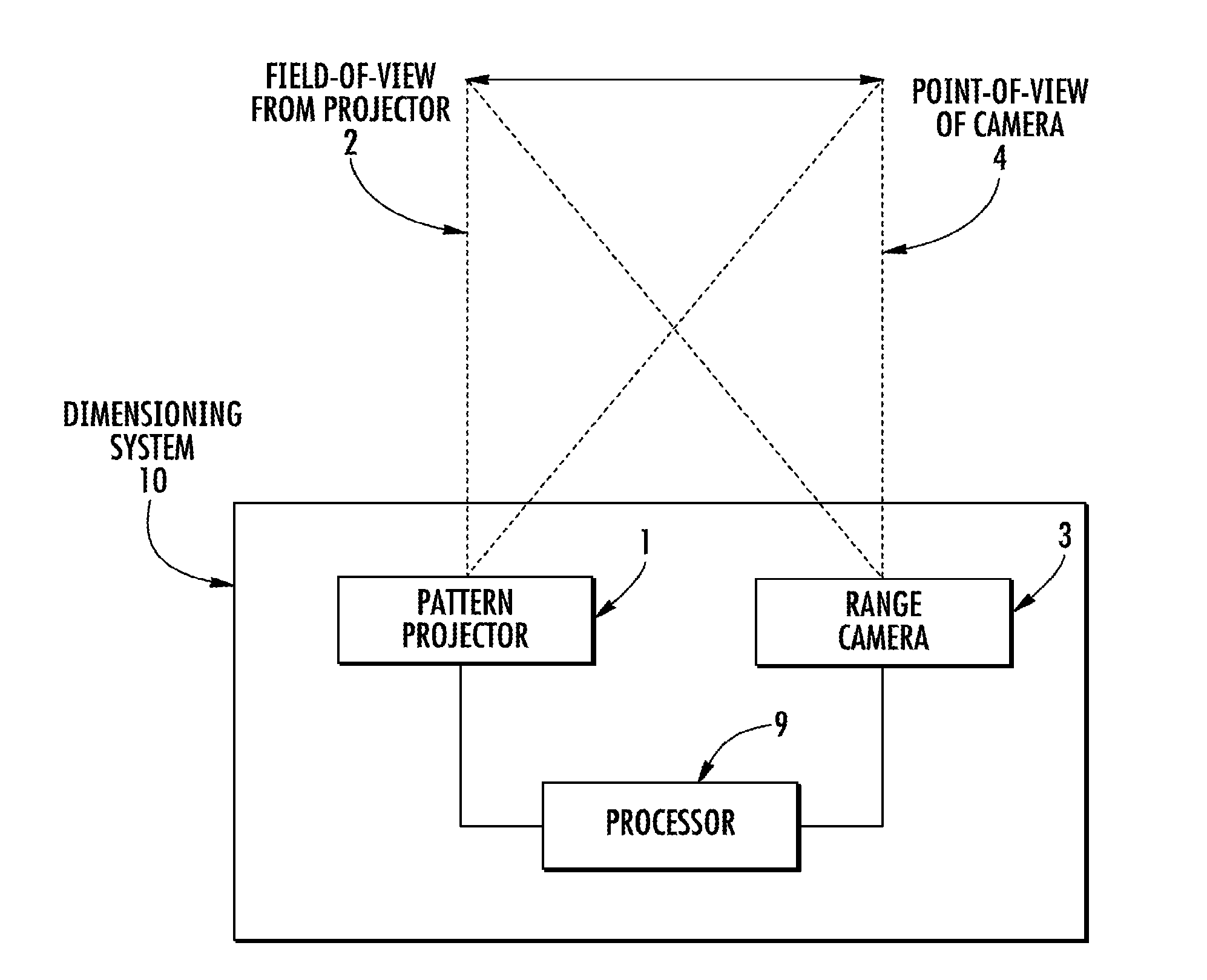
[0035] FIG. 1 schematically depicts a block diagram of a dimensioning system according to an embodiment of the present invention.
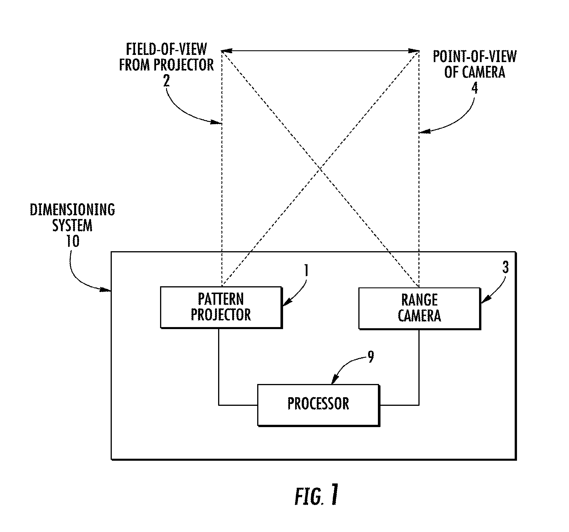
[0036] FIG. 2 graphically depicts the principle of sensing three dimensions using a spatially offset pattern projector and range camera according to an embodiment of the present invention.
[0037] FIG. 3 graphically depicts an implementation of a dimensioning system's pattern projector according to an embodiment of the present invention.
[0038] FIG. 4 graphically depicts the movement of the dimensioning system and/or the object according to an embodiment of the present invention.
[0039] FIG. 5 graphically depicts a flow diagram illustrating a method for dimensioning an object according to an embodiment of the present invention.
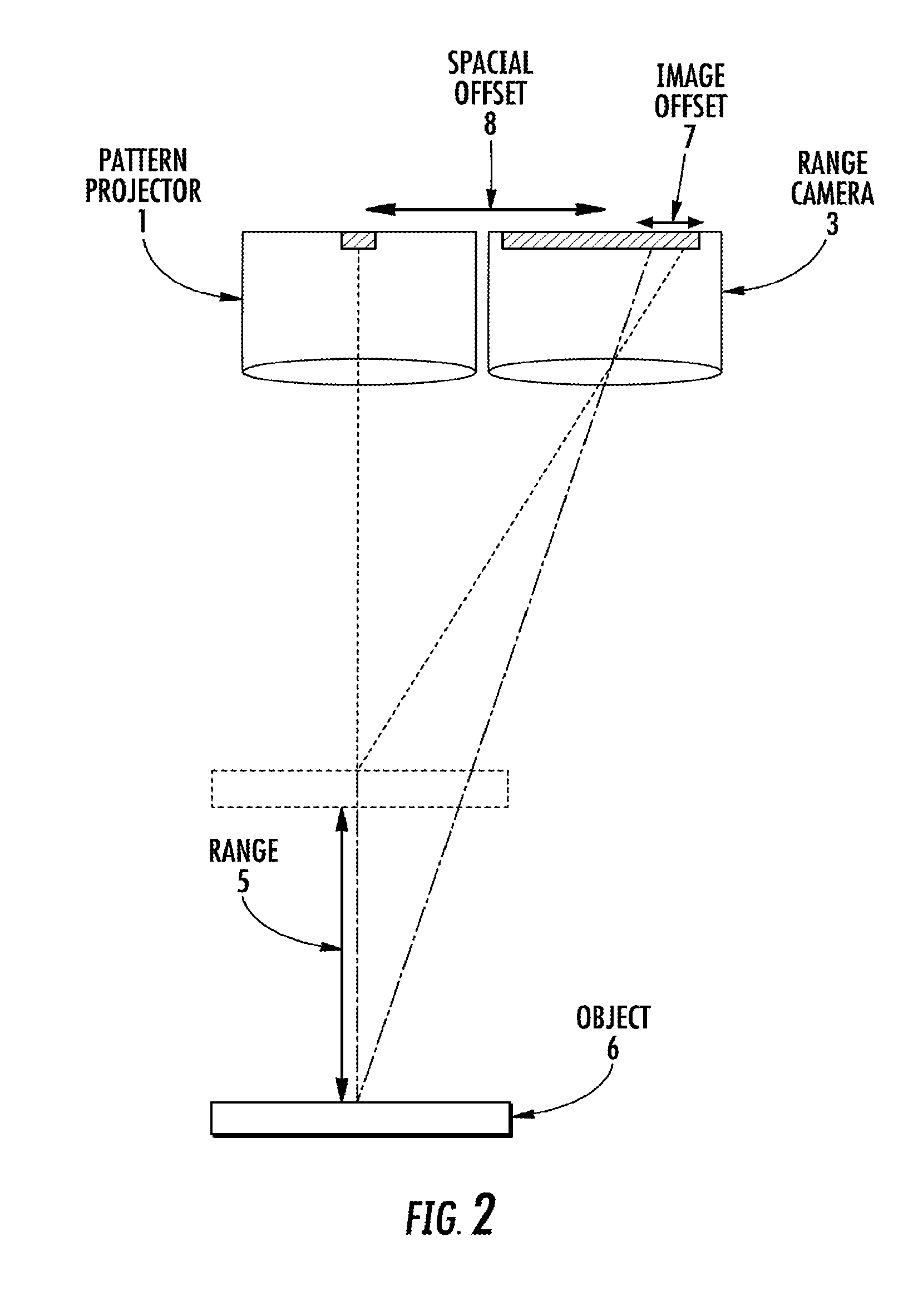
[0040] FIG. 6 graphically depicts the two-dimensional view of an object that contains an obtuse angle according to an embodiment of the present invention.
[0041] FIG. 7 graphically depicts a flow chart representing how one (Mode 1), two (Mode 2), or three (Mode 3) views can be determined automatically according to an embodiment of the present invention so that the minimum bounding box may be provided for use in commerce.
DETAILED DESCRIPTION
[0042] The present invention embraces a method of dimensioning and a dimensioning system with a single sensor (i.e. a single image sensor and camera) that automatically switches modes for capturing the least amount of views for dimensioning various shaped objects. The method of dimensioning and dimensioner of the instant disclosure is generally designed to automatically operate in and switch between one of three modes: [0043] a first mode is automatically used if the object is a cuboid, or has no protrusions and only one obtuse angle that does not face the point of view, where the first mode captures a single view of the object; [0044] a second mode is automatically used if the object includes a single obtuse angle that faces the point of view and no protrusions, where the second mode captures two views of the object; or [0045] a third mode is automatically used if the object includes a protrusion and/or more than one obtuse angle, overhang, protrusion, or combinations thereof, where the third mode captures more than two views of the object. Some advantages of using the disclosed method and system with these three automatic modes may be to calculate a minimum bounding box (MVBB) for use in commerce quickly, accurately and with similar costs to a single mode dimensioning system. As such, the present disclosure is designed to provide a dimensioning method and system that will be marketable and certifiable for use in commerce. The present disclosure improves upon a device that is programmed to always make multiple measurements in order to be certified for commerce to dimension irregular objects. Thus, the instant disclosure may provide a lower cost, yet inflexible approach that involves using a single algorithm that requires the operator to make measurements from different points of view (e.g. from the front and the side or from one side and the other side, etc.). In addition, the instant disclosure may describe an optimized and automated approach in which information about the carton or object to be dimensioned is used to determine how many views are required in order to be certified for commerce. As such, a device incorporating the methods and processes described herein may be approximately the same cost as a standard device with a single sensor but could provide unique certifiable in commerce features in the optical dimensioning market.
[0046] An exemplary dimensioning system is shown in Figure (FIG.) 1. The dimensioning system 10 includes a pattern projector 1 that is configured to project a light (e.g., infrared light) pattern into a field-of-view 2. The light pattern typically comprises points of light arranged in a pattern (i.e., point cloud). The points of light may be (i) sized identically or differently and (ii) may be arranged in some order or pseudo-randomly. The pattern projector may create the light pattern using a light source (e.g., laser, LED, etc.), a pattern creator (e.g., a mask, a diffractive optical element, etc.), and one or more lenses.
[0047] The dimensioning system 10 also includes a range camera 3 configured to capture an image of the projected light pattern that is reflected from the range camera's field-of-view 4. The field-of-view of the range camera 4 and the field-of-view of the pattern projector 2 should overlap but may not necessarily have identical shapes/sizes. The range camera 3 may include one or more lenses to form a real image of the field-of-view 4 onto an image sensor. Light filtering (e.g., infrared filter) may also be used to help detect the reflected pattern by removing stray light and/or ambient light. An image sensor (e.g., CMOS sensor, CCD sensor, etc.) may be used to create a digital image of the light pattern. The range camera may also include the necessary processing (e.g. DSP, FPGA, ASIC, etc.) to obtain 3D data from the light pattern image. As examples, and clearly not limited thereto, the range camera 3 may be based on one or more of: structured light, stereo vision, time-of-flight, the like, and/or combinations thereof.
[0048] As shown in FIG. 2, the pattern projector 1 and the range camera 3 may be spatially offset (e.g., stereoscopically arranged). The spatial offset 8 allows for changes in the range 5 of an object 6 to be detected as an image offset 7 on the range camera's image sensor. The spatial offset 8 may be adjusted to change the image offset 7 to change the resolution at which range differences 5 may be detected. In this way, image offsets in the point-cloud pattern may be converted into 3D data for objects within the dimensioning system's field-of-view.
[0049] The 3D data includes range values for each point of light in the point-cloud image. Further, range values between the points of light in the point-cloud image may be interpolated to create what is known as a range image. A range image is a gray scale image in which each pixel value in the image corresponds to an estimated range between the dimensioning system and a point in the field-of-view. The range camera may output 3D data in the form of point-cloud images or range images.
[0050] A range image may be analyzed using software algorithms running on the dimensioning system's processor 9 (see FIG. 1) to detect objects and determine the object's dimensions. In some cases these algorithms may include steps to create a minimum bounding box (MVBB), which is a computer model of a box that surrounds an object (e.g., an irregularly shaped object) or a collection of objects (e.g., multiple boxes on a pallet). In this case, the dimensioning system may return and even display the dimensions of the MVBB.
[0051] Accurate dimensioning requires high-quality images of the reflected pattern (e.g., point-cloud images). A high quality point-cloud image is one in which the points of light in the pattern are visible on a plurality of the object's surfaces. Low quality point-cloud images may result from a variety of circumstances. For example, the imaged pattern may not be visible one or more surfaces (e.g., surfaces that are blocked from the pattern projector) or fall outside the field-of-view of the pattern projector and/or the range camera. In another example, the light pattern may be partially visible on a surface and/or lack sufficient pattern density (i.e., the number of visible points of light on the surface). In yet another example, the lighting (e.g., glare, shadows) in the object's environment and/or the object's reflectivity (e.g., dark objects) may adversely affect the visibility of the light pattern.
[0052] FIG. 3 graphically depicts a dimensioning system 10 projecting a light pattern 11 onto an object 6 in field-of-view 2. This depiction shows the dimensioning system 10 capturing a single view of object 6, as object 6 is a cuboid (mode 1).
[0053] FIG. 4 illustrates how the movement 12 of the dimensioning system 10 and/or movement 13 of the object 6 may help capture (i.e., sense, sample, etc.) 3D data. The movements 12 and/or 13 may allow for the capture of 3D data from more portions or views of the object 6 than could be obtained with a single view. Range images may be captured and then combined to form a composite range-image. The composite range-image has 3D data from more points on the object. For example, all sides of an object may be sampled during the moving process to obtain 3D data from the entire object. Further, gaps in the pattern (i.e., missing areas in the pattern) may be filled in using this technique.
[0054] In one possible embodiment, the movement of the dimensioning system and/or the object is automatic and does not require user participation. In this embodiment, the dimensioning system may be coupled to movement devices (e.g., actuators, motors, etc.) that adjust the spatial relationship between the dimensioning system and the object. In one example, the object 6 may be placed in a measurement area and the dimensioning system 10 may be moved around the object 12 to collect range images from various perspectives or views as shown in FIG. 4. In another example, a fixed dimensioning system may collect range images as an object 6 is rotated (e.g., on a motorized turntable) 13 as shown in FIG. 4. In these cases, position information may be obtained from the movement device and used to help combine the range images to create the 3D data.
[0055] In another possible embodiment, the movement of the dimensioning system and/or the object is performed by a user. Here messages (e.g., audio, visual, etc.) may be generated by the dimensioning system's processor and conveyed to a user interface (e.g., screen, indicator lights, speaker, etc.). The user may follow the instructions provided by the messages to move the dimensioning-system/object. The instructions may include messages to help a user know (i) how far to move the dimensioning-system/object, (ii) how fast to move the dimensioning-system/object, (iii) to move the dimensioning system/object to a particular location, and (iv) how long to continue moving the dimensioning-system/object (e.g., when to stop moving). For example, the dimensioning system may be handheld and the user may move the dimensioning system to change perspective. In this case, the dimensioning system may be configured to gather tracking information (e.g., sense its position and orientation within the environment) to help combine the range images.
[0056] In general, the dimensioning system may be moved in a variety of ways as the views and range images are captured. In some cases, however, this movement may have certain requirements to facilitate combining. For example, movements may be limited to movements having a constant range between the dimensioning system and the object, as changes in range can affect the image size of the light-pattern/object. In another example, the movement may be limited to a certain path having a particular starting point and ending point. This path may be determined using an expected object size/shape.
[0057] The requirements for movement may be reduced through the use of simultaneous localization and mapping (SLAM). SLAM is a computer algorithm that uses images (e.g., range images) of an environment to update the position of the imager (e.g., dimensioning system). When moving a dimensioning-system, for example, SLAM algorithms may detect features (i.e., landmarks) in a captured range image and then compare these landmarks to landmarks found in previously captured range images in order to update the position of the dimensioning system. This position information may be used to help combine the range images.
[0058] Combining range images may typically be achieved using image-stitching. Image-stitching refers to computer algorithms that transform, register, and blend a plurality of constituent images to form a single composite image. The image-stitching algorithms may first determine an appropriate mathematical model to relate the pixel coordinates for constituent images to the pixel coordinates of a target composite-image surface (e.g., plane, cylinder, sphere, etc.). This involves transforming (e.g., warping) the images to the target composite-image surface. The transformed images may then registered to one another (e.g., using feature detection and mapping) and merged (e.g., blended) to remove edge effects.
[0059] While range images have pixels to represent range instead of reflected light, they are like conventional digital images in most other regards. As such, the principles of image-stitching described thus far may be applied equally to range images (or point-cloud images).
[0060] In one embodiment, the dimensioning system may be incorporated into a handheld barcode scanner. Often parcels may have a bar code symbol for identification of the individual item (serialized). As such, the incorporation of the instant dimensioning system into a barcode scanner could be a big speed advantage to look-up the bar code data on-line, or stored in a local database, to find out whether the dimensions have already been determined at an earlier stage of the transport. A further enhancement would be for high-value items that are often counterfeited, to compare the stored dimensions to the measured dimensions and flag a discrepancy.
[0061] FIG. 5 graphically depicts a flow diagram illustrating a method 100 for dimensioning an object. The method begins with positioning 20 a dimensioning system and/or object so that at least a portion on an object is contained within the dimensioning system's point-of-view. The method 100 then automatically determines 110 the number of views required to dimension the object. The number of views captured with range images and dimensional data is automatically determined based on one of three modes: a first mode, a second mode, and a third mode based on an algorithm. The first mode is automatically used if the object is a cuboid, or has no protrusions and only one obtuse angle that does not face the point of view, where the first mode captures a single view of the object. The second mode is automatically used if the object includes a single obtuse angle that faces the point of view and no protrusions, where the second mode captures two views of the object. The third mode is automatically used if the object includes a protrusion and/or more than one obtuse angle, overhang, protrusion, or combinations thereof, where the third mode captures more than two views of the object.
[0062] Once the number of required views is determined, the method first captures 130 range images of an initial field-of-view. If the required number of views is not captured, the dimensioning system and/or the object is then moved 160 so that another portion of the object is within the field-of-view and another range image is captured 130. This process of moving and capturing is repeated until the required number of views and associated range images are captured 130.
[0063] Once the required number of views is captured, the plurality of range images may then combined 170 to form a composite range-image, and the composite range-image may be used to dimension 190 the object.
[0064] In one exemplary embodiment, once the dimensioning 190 is complete, the dimensions of the minimum bounding box (MVBB) may be calculated 200. In select embodiments, these calculated dimensions of the MVBB may be displayed and/or transmitted 210.
[0065] In one exemplary embodiment, the dimensioning system may create messages 150 to guide the movement of the dimensioning system and/or the object as described previously. In select embodiments, this moving 150 of the dimensioning system or the object may be determined based on one or more of the following: [0066] determining if there is a side of the object in the view that is non-flat, and if so, moving the dimensioning system or the object so that the dimensioning system's field-of-view contains a different portion of the object; [0067] detecting if there is an obtuse angle that faces the point of view, and if so, moving the dimensioning system or the object so that the dimensioning system's field-of-view contains a different portion of the object; and [0068] detecting if there is another obtuse angle and/or a protrusion, and if so, moving the dimensioning system or the object so that the dimensioning system's field-of-view contains a different portion of the object.
[0069] The present disclosure recognizes that particular features of an object to be dimensioned (i.e. a carton or normal box) can be detected in the first view and, based on this analysis, change modes, then require two or more points of view to be dimensioned. The present disclosure may provide a dimensioner that can be easily moved if handheld, or alternatively, a carton placed on a static dimensioner (e.g. auto cube) can be turned to a different orientation so that an automatic mode-switching device can be used to generate always the correct dimensions, particularly in countries with stringent requirements for certification of dimensioning irregular objects.
[0070] Referring to Mode 1, if the carton is a cuboid or "normal" box, then no matter from which point of view it is viewed, the same dimensioner result will occur (within the measuring tolerance provided by the device, which may be called "d"). Consequently, a single image will produce valid results for use in commerce.
[0071] Referring to Mode 2, if the object has an obtuse angle, then depending on which view the dimensioning camera has, different sets of bounding box dimensions result. If the obtuse angle is facing the camera, then a "shadow" or hidden area will result causing the dimensions of the bounding box to be larger than the minimum. The operator or system needs to be instructed to move the dimensioner or rearrange the object so that another view is obtained. As long as the other view does not have the obtuse angle facing the dimensioner, the result will be the smallest bounding box.
[0072] FIG. 6 graphically depicts the two-dimensional view of an object that contains an obtuse angle (angle F) according to an embodiment of the present invention. If the object is viewed from the right (side b) or if the object is flipped over and viewed with the obtuse angle facing away (side c down), then a smaller bounding box will result. It is the smallest bounding box that is the one that must be reported for use in commerce. Assume for this discussion of FIG. 6, that the other end of the carton is identical and the remaining sides are flat and perpendicular to the ends. If the carton is viewed from above, as depicted with the arrows (facing side c) then the dimensioner will not see under the overhang and a "shadow" will be cast. This viewing scenario will produce a larger bounding box than if viewed from the right or if the carton is rearranged so that side "c" is down.
[0073] Referring to Mode 3, if the object has a side that is not flat, then it may be overhanging another side and causing a hidden area. Consequently, another view would be required to see under the overhang. Similarly, if the object has a protrusion, then it may cause a shadow and potentially, a bounding box that is not the minimum. Again, another view would be required to see under the protrusion. In some cases, especially if there is more than one obtuse angle, overhang, or protrusion or if there is a combination, then the dimensioner must view the object from all three orthogonal sides to be sure to capture the smallest bounding box.
[0074] In a handheld scenario, the operator may be instructed to move the dimensioner or rearrange the carton to obtain the second and/or third images. In the case of a fixed dimensioner, the operator may be instructed to rearrange the carton to obtain the second and/or third image, or this movement may be automated.
[0075] Once the requisite number of views and images are collected, the device may simply compare the values and choose the set of dimensions that produce the smallest bounding box. If the operator does not collect the requisite images, then the device must not provide any dimensions (e.g. issue a static failure notice).
[0076] Referring now to FIG. 7, a summary of one embodiment of automatic mode switching in a volume dimensioner is shown as a flowchart. The flowchart shows how on (Mode 1), two (Mode 2), or three (Mode 3) points of view can be determined automatically so that the dimensions of the MVBB can always be provided. The overview of the disclosure is that the dimensioner automatically determines whether it has a safe view of the object and can guarantee that the smallest bounding box is reported. Ultimately, it may be necessary to require three orthogonal views by the user so that a customer will not be overcharged. Thus, the dimensioner could be certified for use in commerce
[0077] To supplement the present disclosure, this application incorporates entirely by reference the following commonly assigned patents, patent application publications, and patent applications: [0078] U.S. Pat. No. 6,832,725; U.S. Pat. No. 7,128,266; [0079] U.S. Pat. No. 7,159,783; U.S. Pat. No. 7,413,127; [0080] U.S. Pat. No. 7,726,575; U.S. Pat. No. 8,294,969; [0081] U.S. Pat. No. 8,317,105; U.S. Pat. No. 8,322,622; [0082] U.S. Pat. No. 8,366,005; U.S. Pat. No. 8,371,507; [0083] U.S. Pat. No. 8,376,233; U.S. Pat. No. 8,381,979; [0084] U.S. Pat. No. 8,390,909; U.S. Pat. No. 8,408,464; [0085] U.S. Pat. No. 8,408,468; U.S. Pat. No. 8,408,469; [0086] U.S. Pat. No. 8,424,768; U.S. Pat. No. 8,448,863; [0087] U.S. Pat. No. 8,457,013; U.S. Pat. No. 8,459,557; [0088] U.S. Pat. No. 8,469,272; U.S. Pat. No. 8,474,712; [0089] U.S. Pat. No. 8,479,992; U.S. Pat. No. 8,490,877; [0090] U.S. Pat. No. 8,517,271; U.S. Pat. No. 8,523,076; [0091] U.S. Pat. No. 8,528,818; U.S. Pat. No. 8,544,737; [0092] U.S. Pat. No. 8,548,242; U.S. Pat. No. 8,548,420; [0093] U.S. Pat. No. 8,550,335; U.S. Pat. No. 8,550,354; [0094] U.S. Pat. No. 8,550,357; U.S. Pat. No. 8,556,174; [0095] U.S. Pat. No. 8,556,176; U.S. Pat. No. 8,556,177; [0096] U.S. Pat. No. 8,559,767; U.S. Pat. No. 8,599,957; [0097] U.S. Pat. No. 8,561,895; U.S. Pat. No. 8,561,903; [0098] U.S. Pat. No. 8,561,905; U.S. Pat. No. 8,565,107; [0099] U.S. Pat. No. 8,571,307; U.S. Pat. No. 8,579,200; [0100] U.S. Pat. No. 8,583,924; U.S. Pat. No. 8,584,945; [0101] U.S. Pat. No. 8,587,595; U.S. Pat. No. 8,587,697; [0102] U.S. Pat. No. 8,588,869; U.S. Pat. No. 8,590,789; [0103] U.S. Pat. No. 8,596,539; U.S. Pat. No. 8,596,542; [0104] U.S. Pat. No. 8,596,543; U.S. Pat. No. 8,599,271; [0105] U.S. Pat. No. 8,599,957; U.S. Pat. No. 8,600,158; [0106] U.S. Pat. No. 8,600,167; U.S. Pat. No. 8,602,309; [0107] U.S. Pat. No. 8,608,053; U.S. Pat. No. 8,608,071; [0108] U.S. Pat. No. 8,611,309; U.S. Pat. No. 8,615,487; [0109] U.S. Pat. No. 8,616,454; U.S. Pat. No. 8,621,123; [0110] U.S. Pat. No. 8,622,303; U.S. Pat. No. 8,628,013; [0111] U.S. Pat. No. 8,628,015; U.S. Pat. No. 8,628,016; [0112] U.S. Pat. No. 8,629,926; U.S. Pat. No. 8,630,491; [0113] U.S. Pat. No. 8,635,309; U.S. Pat. No. 8,636,200; [0114] U.S. Pat. No. 8,636,212; U.S. Pat. No. 8,636,215; [0115] U.S. Pat. No. 8,636,224; U.S. Pat. No. 8,638,806; [0116] U.S. Pat. No. 8,640,958; U.S. Pat. No. 8,640,960; [0117] U.S. Pat. No. 8,643,717; U.S. Pat. No. 8,646,692; [0118] U.S. Pat. No. 8,646,694; U.S. Pat. No. 8,657,200; [0119] U.S. Pat. No. 8,659,397; U.S. Pat. No. 8,668,149; [0120] U.S. Pat. No. 8,678,285; U.S. Pat. No. 8,678,286; [0121] U.S. Pat. No. 8,682,077; U.S. Pat. No. 8,687,282; [0122] U.S. Pat. No. 8,692,927; U.S. Pat. No. 8,695,880; [0123] U.S. Pat. No. 8,698,949; U.S. Pat. No. 8,717,494; [0124] U.S. Pat. No. 8,717,494; U.S. Pat. No. 8,720,783; [0125] U.S. Pat. No. 8,723,804; U.S. Pat. No. 8,723,904; [0126] U.S. Pat. No. 8,727,223; U.S. Pat. No. D702,237; [0127] U.S. Pat. No. 8,740,082; U.S. Pat. No. 8,740,085; [0128] U.S. Pat. No. 8,746,563; U.S. Pat. No. 8,750,445; [0129] U.S. Pat. No. 8,752,766; U.S. Pat. No. 8,756,059; [0130] U.S. Pat. No. 8,757,495; U.S. Pat. No. 8,760,563; [0131] U.S. Pat. No. 8,763,909; U.S. Pat. No. 8,777,108; [0132] U.S. Pat. No. 8,777,109; U.S. Pat. No. 8,779,898; [0133] U.S. Pat. No. 8,781,520; U.S. Pat. No. 8,783,573; [0134] U.S. Pat. No. 8,789,757; U.S. Pat. No. 8,789,758; [0135] U.S. Pat. No. 8,789,759; U.S. Pat. No. 8,794,520; [0136] U.S. Pat. No. 8,794,522; U.S. Pat. No. 8,794,525; [0137] U.S. Pat. No. 8,794,526; U.S. Pat. No. 8,798,367; [0138] U.S. Pat. No. 8,807,431; U.S. Pat. No. 8,807,432; [0139] U.S. Pat. No. 8,820,630; U.S. Pat. No. 8,822,848; [0140] U.S. Pat. No. 8,824,692; U.S. Pat. No. 8,824,696; [0141] U.S. Pat. No. 8,842,849; U.S. Pat. No. 8,844,822; [0142] U.S. Pat. No. 8,844,823; U.S. Pat. No. 8,849,019; [0143] U.S. Pat. No. 8,851,383; U.S. Pat. No. 8,854,633; [0144] U.S. Pat. No. 8,866,963; U.S. Pat. No. 8,868,421; [0145] U.S. Pat. No. 8,868,519; U.S. Pat. No. 8,868,802; [0146] U.S. Pat. No. 8,868,803; U.S. Pat. No. 8,870,074; [0147] U.S. Pat. No. 8,879,639; U.S. Pat. No. 8,880,426; [0148] U.S. Pat. No. 8,881,983; U.S. Pat. No. 8,881,987; [0149] U.S. Pat. No. 8,903,172; U.S. Pat. No. 8,908,995; [0150] U.S. Pat. No. 8,910,870; U.S. Pat. No. 8,910,875; [0151] U.S. Pat. No. 8,914,290; U.S. Pat. No. 8,914,788; [0152] U.S. Pat. No. 8,915,439; U.S. Pat. No. 8,915,444; [0153] U.S. Pat. No. 8,916,789; U.S. Pat. No. 8,918,250; [0154] U.S. Pat. No. 8,918,564; U.S. Pat. No. 8,925,818; [0155] U.S. Pat. No. 8,939,374; U.S. Pat. No. 8,942,480; [0156] U.S. Pat. No. 8,944,313; U.S. Pat. No. 8,944,327; [0157] U.S. Pat. No. 8,944,332; U.S. Pat. No. 8,950,678; [0158] U.S. Pat. No. 8,967,468; U.S. Pat. No. 8,971,346; [0159] U.S. Pat. No. 8,976,030; U.S. Pat. No. 8,976,368; [0160] U.S. Pat. No. 8,978,981; U.S. Pat. No. 8,978,983; [0161] U.S. Pat. No. 8,978,984; U.S. Pat. No. 8,985,456; [0162] U.S. Pat. No. 8,985,457; U.S. Pat. No. 8,985,459; [0163] U.S. Pat. No. 8,985,461; U.S. Pat. No. 8,988,578; [0164] U.S. Pat. No. 8,988,590; U.S. Pat. No. 8,991,704; [0165] U.S. Pat. No. 8,996,194; U.S. Pat. No. 8,996,384; [0166] U.S. Pat. No. 9,002,641; U.S. Pat. No. 9,007,368; [0167] U.S. Pat. No. 9,010,641; U.S. Pat. No. 9,015,513; [0168] U.S. Pat. No. 9,016,576; U.S. Pat. No. 9,022,288; [0169] U.S. Pat. No. 9,030,964; U.S. Pat. No. 9,033,240; [0170] U.S. Pat. No. 9,033,242; U.S. Pat. No. 9,036,054; [0171] U.S. Pat. No. 9,037,344; U.S. Pat. No. 9,038,911; [0172] U.S. Pat. No. 9,038,915; U.S. Pat. No. 9,047,098; [0173] U.S. Pat. No. 9,047,359; U.S. Pat. No. 9,047,420; [0174] U.S. Pat. No. 9,047,525; U.S. Pat. No. 9,047,531; [0175] U.S. Pat. No. 9,053,055; U.S. Pat. No. 9,053,378; [0176] U.S. Pat. No. 9,053,380; U.S. Pat. No. 9,058,526; [0177] U.S. Pat. No. 9,064,165; U.S. Pat. No. 9,064,167; [0178] U.S. Pat. No. 9,064,168; U.S. Pat. No. 9,064,254; [0179] U.S. Pat. No. 9,066,032; U.S. Pat. No. 9,070,032; [0180] U.S. Design Pat. No. D716,285; [0181] U.S. Design Pat. No. D723,560; [0182] U.S. Design Pat. No. D730,357; [0183] U.S. Design Pat. No. D730,901; [0184] U.S. Design Pat. No. D730,902; [0185] U.S. Design Pat. No. D733,112; [0186] U.S. Design Pat. No. D734,339; [0187] International Publication No. 2013/163789; [0188] International Publication No. 2013/173985; [0189] International Publication No. 2014/019130; [0190] International Publication No. 2014/110495; [0191] U.S. Patent Application Publication No. 2008/0185432; [0192] U.S. Patent Application Publication No. 2009/0134221; [0193] U.S. Patent Application Publication No. 2010/0177080; [0194] U.S. Patent Application Publication No. 2010/0177076; [0195] U.S. Patent Application Publication No. 2010/0177707; [0196] U.S. Patent Application Publication No. 2010/0177749; [0197] U.S. Patent Application Publication No. 2010/0265880; [0198] U.S. Patent Application Publication No. 2011/0202554; [0199] U.S. Patent Application Publication No. 2012/0111946; [0200] U.S. Patent Application Publication No. 2012/0168511; [0201] U.S. Patent Application Publication No. 2012/0168512; [0202] U.S. Patent Application Publication No. 2012/0193423; [0203] U.S. Patent Application Publication No. 2012/0203647; [0204] U.S. Patent Application Publication No. 2012/0223141; [0205] U.S. Patent Application Publication No. 2012/0228382; [0206] U.S. Patent Application Publication No. 2012/0248188; [0207] U.S. Patent Application Publication No. 2013/0043312; [0208] U.S. Patent Application Publication No. 2013/0082104; [0209] U.S. Patent Application Publication No. 2013/0175341; [0210] U.S. Patent Application Publication No. 2013/0175343; [0211] U.S. Patent Application Publication No. 2013/0257744; [0212] U.S. Patent Application Publication No. 2013/0257759; [0213] U.S. Patent Application Publication No. 2013/0270346; [0214] U.S. Patent Application Publication No. 2013/0287258; [0215] U.S. Patent Application Publication No. 2013/0292475; [0216] U.S. Patent Application Publication No. 2013/0292477; [0217] U.S. Patent Application Publication No. 2013/0293539; [0218] U.S. Patent Application Publication No. 2013/0293540; [0219] U.S. Patent Application Publication No. 2013/0306728; [0220] U.S. Patent Application Publication No. 2013/0306731; [0221] U.S. Patent Application Publication No. 2013/0307964; [0222] U.S. Patent Application Publication No. 2013/0308625; [0223] U.S. Patent Application Publication No. 2013/0313324; [0224] U.S. Patent Application Publication No. 2013/0313325; [0225] U.S. Patent Application Publication No. 2013/0342717; [0226] U.S. Patent Application Publication No. 2014/0001267; [0227] U.S. Patent Application Publication No. 2014/0008439; [0228] U.S. Patent Application Publication No. 2014/0025584; [0229] U.S. Patent Application Publication No. 2014/0034734; [0230] U.S. Patent Application Publication No. 2014/0036848; [0231] U.S. Patent Application Publication No. 2014/0039693; [0232] U.S. Patent Application Publication No. 2014/0042814; [0233] U.S. Patent Application Publication No. 2014/0049120; [0234] U.S. Patent Application Publication No. 2014/0049635; [0235] U.S. Patent Application Publication No. 2014/0061306; [0236] U.S. Patent Application Publication No. 2014/0063289; [0237] U.S. Patent Application Publication No. 2014/0066136; [0238] U.S. Patent Application Publication No. 2014/0067692; [0239] U.S. Patent Application Publication No. 2014/0070005; [0240] U.S. Patent Application Publication No. 2014/0071840; [0241] U.S. Patent Application Publication No. 2014/0074746; [0242] U.S. Patent Application Publication No. 2014/0076974; [0243] U.S. Patent Application Publication No. 2014/0078341; [0244] U.S. Patent Application Publication No. 2014/0078345; [0245] U.S. Patent Application Publication No. 2014/0097249; [0246] U.S. Patent Application Publication No. 2014/0098792; [0247] U.S. Patent Application Publication No. 2014/0100813; [0248] U.S. Patent Application Publication No. 2014/0103115; [0249] U.S. Patent Application Publication No. 2014/0104413; [0250] U.S. Patent Application Publication No. 2014/0104414; [0251] U.S. Patent Application Publication No. 2014/0104416; [0252] U.S. Patent Application Publication No. 2014/0104451; [0253] U.S. Patent Application Publication No. 2014/0106594; [0254] U.S. Patent Application Publication No. 2014/0106725; [0255] U.S. Patent Application Publication No. 2014/0108010; [0256] U.S. Patent Application Publication No. 2014/0108402; [0257] U.S. Patent Application Publication No. 2014/0110485; [0258] U.S. Patent Application Publication No. 2014/0114530; [0259] U.S. Patent Application Publication No. 2014/0124577; [0260] U.S. Patent Application Publication No. 2014/0124579; [0261] U.S. Patent Application Publication No. 2014/0125842; [0262] U.S. Patent Application Publication No. 2014/0125853; [0263] U.S. Patent Application Publication No. 2014/0125999; [0264] U.S. Patent Application Publication No. 2014/0129378; [0265] U.S. Patent Application Publication No. 2014/0131438; [0266] U.S. Patent Application Publication No. 2014/0131441; [0267] U.S. Patent Application Publication No. 2014/0131443; [0268] U.S. Patent Application Publication No. 2014/0131444; [0269] U.S. Patent Application Publication No. 2014/0131445; [0270] U.S. Patent Application Publication No. 2014/0131448; [0271] U.S. Patent Application Publication No. 2014/0133379; [0272] U.S. Patent Application Publication No. 2014/0136208; [0273] U.S. Patent Application Publication No. 2014/0140585; [0274] U.S. Patent Application Publication No. 2014/0151453; [0275] U.S. Patent Application Publication No. 2014/0152882; [0276] U.S. Patent Application Publication No. 2014/0158770; [0277] U.S. Patent Application Publication No. 2014/0159869; [0278] U.S. Patent Application Publication No. 2014/0166755; [0279] U.S. Patent Application Publication No. 2014/0166759; [0280] U.S. Patent Application Publication No. 2014/0168787; [0281] U.S. Patent Application Publication No. 2014/0175165; [0282] U.S. Patent Application Publication No. 2014/0175172; [0283] U.S. Patent Application Publication No. 2014/0191644; [0284] U.S. Patent Application Publication No. 2014/0191913; [0285] U.S. Patent Application Publication No. 2014/0197238; [0286] U.S. Patent Application Publication No. 2014/0197239; [0287] U.S. Patent Application Publication No. 2014/0197304; [0288] U.S. Patent Application Publication No. 2014/0214631; [0289] U.S. Patent Application Publication No. 2014/0217166; [0290] U.S. Patent Application Publication No. 2014/0217180; [0291] U.S. Patent Application Publication No. 2014/0231500; [0292] U.S. Patent Application Publication No. 2014/0232930; [0293] U.S. Patent Application Publication No. 2014/0247315; [0294] U.S. Patent Application Publication No. 2014/0263493; [0295] U.S. Patent Application Publication No. 2014/0263645; [0296] U.S. Patent Application Publication No. 2014/0267609; [0297] U.S. Patent Application Publication No. 2014/0270196; [0298] U.S. Patent Application Publication No. 2014/0270229; [0299] U.S. Patent Application Publication No. 2014/0278387; [0300] U.S. Patent Application Publication No. 2014/0278391; [0301] U.S. Patent Application Publication No. 2014/0282210; [0302] U.S. Patent Application Publication No. 2014/0284384; [0303] U.S. Patent Application Publication No. 2014/0288933; [0304] U.S. Patent Application Publication No. 2014/0297058; [0305] U.S. Patent Application Publication No. 2014/0299665; [0306] U.S. Patent Application Publication No. 2014/0312121; [0307] U.S. Patent Application Publication No. 2014/0319220; [0308] U.S. Patent Application Publication No. 2014/0319221; [0309] U.S. Patent Application Publication No. 2014/0326787; [0310] U.S. Patent Application Publication No. 2014/0332590; [0311] U.S. Patent Application Publication No. 2014/0344943; [0312] U.S. Patent Application Publication No. 2014/0346233; [0313] U.S. Patent Application Publication No. 2014/0351317; [0314] U.S. Patent Application Publication No. 2014/0353373; [0315] U.S. Patent Application Publication No. 2014/0361073; [0316] U.S. Patent Application Publication No. 2014/0361082; [0317] U.S. Patent Application Publication No. 2014/0362184; [0318] U.S. Patent Application Publication No. 2014/0363015; [0319] U.S. Patent Application Publication No. 2014/0369511; [0320] U.S. Patent Application Publication No. 2014/0374483; [0321] U.S. Patent Application Publication No. 2014/0374485; [0322] U.S. Patent Application Publication No. 2015/0001301; [0323] U.S. Patent Application Publication No. 2015/0001304; [0324] U.S. Patent Application Publication No. 2015/0003673; [0325] U.S. Patent Application Publication No. 2015/0009338; [0326] U.S. Patent Application Publication No. 2015/0009610; [0327] U.S. Patent Application Publication No. 2015/0014416; [0328] U.S. Patent Application Publication No. 2015/0021397; [0329] U.S. Patent Application Publication No. 2015/0028102; [0330] U.S. Patent Application Publication No. 2015/0028103;
[0331] U.S. Patent Application Publication No. 2015/0028104; [0332] U.S. Patent Application Publication No. 2015/0029002; [0333] U.S. Patent Application Publication No. 2015/0032709; [0334] U.S. Patent Application Publication No. 2015/0039309; [0335] U.S. Patent Application Publication No. 2015/0039878; [0336] U.S. Patent Application Publication No. 2015/0040378; [0337] U.S. Patent Application Publication No. 2015/0048168; [0338] U.S. Patent Application Publication No. 2015/0049347; [0339] U.S. Patent Application Publication No. 2015/0051992; [0340] U.S. Patent Application Publication No. 2015/0053766; [0341] U.S. Patent Application Publication No. 2015/0053768; [0342] U.S. Patent Application Publication No. 2015/0053769; [0343] U.S. Patent Application Publication No. 2015/0060544; [0344] U.S. Patent Application Publication No. 2015/0062366; [0345] U.S. Patent Application Publication No. 2015/0063215; [0346] U.S. Patent Application Publication No. 2015/0063676; [0347] U.S. Patent Application Publication No. 2015/0069130; [0348] U.S. Patent Application Publication No. 2015/0071819; [0349] U.S. Patent Application Publication No. 2015/0083800; [0350] U.S. Patent Application Publication No. 2015/0086114; [0351] U.S. Patent Application Publication No. 2015/0088522; [0352] U.S. Patent Application Publication No. 2015/0096872; [0353] U.S. Patent Application Publication No. 2015/0099557; [0354] U.S. Patent Application Publication No. 2015/0100196; [0355] U.S. Patent Application Publication No. 2015/0102109; [0356] U.S. Patent Application Publication No. 2015/0115035; [0357] U.S. Patent Application Publication No. 2015/0127791; [0358] U.S. Patent Application Publication No. 2015/0128116; [0359] U.S. Patent Application Publication No. 2015/0129659; [0360] U.S. Patent Application Publication No. 2015/0133047; [0361] U.S. Patent Application Publication No. 2015/0134470; [0362] U.S. Patent Application Publication No. 2015/0136851; [0363] U.S. Patent Application Publication No. 2015/0136854; [0364] U.S. Patent Application Publication No. 2015/0142492; [0365] U.S. Patent Application Publication No. 2015/0144692; [0366] U.S. Patent Application Publication No. 2015/0144698; [0367] U.S. Patent Application Publication No. 2015/0144701; [0368] U.S. Patent Application Publication No. 2015/0149946; [0369] U.S. Patent Application Publication No. 2015/0161429; [0370] U.S. Patent Application Publication No. 2015/0169925; [0371] U.S. Patent Application Publication No. 2015/0169929; [0372] U.S. Patent Application Publication No. 2015/0178523; [0373] U.S. Patent Application Publication No. 2015/0178534; [0374] U.S. Patent Application Publication No. 2015/0178535; [0375] U.S. Patent Application Publication No. 2015/0178536; [0376] U.S. Patent Application Publication No. 2015/0178537; [0377] U.S. Patent Application Publication No. 2015/0181093; [0378] U.S. Patent Application Publication No. 2015/0181109; [0379] U.S. patent application Ser. No. 13/367,978 for a Laser Scanning Module Employing an Elastomeric U-Hinge Based Laser Scanning Assembly, filed Feb. 7, 2012 (Feng et al.); [0380] U.S. patent application Ser. No. 29/458,405 for an Electronic Device, filed Jun. 19, 2013 (Fitch et al.); [0381] U.S. patent application Ser. No. 29/459,620 for an Electronic Device Enclosure, filed Jul. 2, 2013 (London et al.); [0382] U.S. patent application Ser. No. 29/468,118 for an Electronic Device Case, filed Sep. 26, 2013 (Oberpriller et al.); [0383] U.S. patent application Ser. No. 14/150,393 for Indicia-reader Having Unitary Construction Scanner, filed Jan. 8, 2014 (Colavito et al.); [0384] U.S. patent application Ser. No. 14/200,405 for Indicia Reader for Size-Limited Applications filed Mar. 7, 2014 (Feng et al.); [0385] U.S. patent application Ser. No. 14/231,898 for Hand-Mounted Indicia-Reading Device with Finger Motion Triggering filed Apr. 1, 2014 (Van Horn et al.); [0386] U.S. patent application Ser. No. 29/486,759 for an Imaging Terminal, filed Apr. 2, 2014 (Oberpriller et al.); [0387] U.S. patent application Ser. No. 14/257,364 for Docking System and Method Using Near Field Communication filed Apr. 21, 2014 (Showering); [0388] U.S. patent application Ser. No. 14/264,173 for Autofocus Lens System for Indicia Readers filed Apr. 29, 2014 (Ackley et al.); [0389] U.S. patent application Ser. No. 14/277,337 for MULTIPURPOSE OPTICAL READER, filed May 14, 2014 (Jovanovski et al.); [0390] U.S. patent application Ser. No. 14/283,282 for TERMINAL HAVING ILLUMINATION AND FOCUS CONTROL filed May 21, 2014 (Liu et al.); [0391] U.S. patent application Ser. No. 14/327,827 for a MOBILE-PHONE ADAPTER FOR ELECTRONIC TRANSACTIONS, filed Jul. 10, 2014 (Hejl); [0392] U.S. patent application Ser. No. 14/334,934 for a SYSTEM AND METHOD FOR INDICIA VERIFICATION, filed Jul. 18, 2014 (Hejl); [0393] U.S. patent application Ser. No. 14/339,708 for LASER SCANNING CODE SYMBOL READING SYSTEM, filed Jul. 24, 2014 (Xian et al.); [0394] U.S. patent application Ser. No. 14/340,627 for an AXIALLY REINFORCED FLEXIBLE SCAN ELEMENT, filed Jul. 25, 2014 (Rueblinger et al.); [0395] U.S. patent application Ser. No. 14/446,391 for MULTIFUNCTION POINT OF SALE APPARATUS WITH OPTICAL SIGNATURE CAPTURE filed Jul. 30, 2014 (Good et al.); [0396] U.S. patent application Ser. No. 14/452,697 for INTERACTIVE INDICIA READER, filed Aug. 6, 2014 (Todeschini); [0397] U.S. patent application Ser. No. 14/453,019 for DIMENSIONING SYSTEM WITH GUIDED ALIGNMENT, filed Aug. 6, 2014 (Li et al.); [0398] U.S. patent application Ser. No. 14/462,801 for MOBILE COMPUTING DEVICE WITH DATA COGNITION SOFTWARE, filed on Aug. 19, 2014 (Todeschini et al.); [0399] U.S. patent application Ser. No. 14/483,056 for VARIABLE DEPTH OF FIELD BARCODE SCANNER filed Sep. 10, 2014 (McCloskey et al.); [0400] U.S. patent application Ser. No. 14/513,808 for IDENTIFYING INVENTORY ITEMS IN A STORAGE FACILITY filed Oct. 14, 2014 (Singel et al.); [0401] U.S. patent application Ser. No. 14/519,195 for HANDHELD DIMENSIONING SYSTEM WITH FEEDBACK filed Oct. 21, 2014 (Laffargue et al.); [0402] U.S. patent application Ser. No. 14/519,179 for DIMENSIONING SYSTEM WITH MULTIPATH INTERFERENCE MITIGATION filed Oct. 21, 2014 (Thuries et al.); [0403] U.S. patent application Ser. No. 14/519,211 for SYSTEM AND METHOD FOR DIMENSIONING filed Oct. 21, 2014 (Ackley et al.); [0404] U.S. patent application Ser. No. 14/519,233 for HANDHELD DIMENSIONER WITH DATA-QUALITY INDICATION filed Oct. 21, 2014 (Laffargue et al.); [0405] U.S. patent application Ser. No. 14/519,249 for HANDHELD DIMENSIONING SYSTEM WITH MEASUREMENT-CONFORMANCE FEEDBACK filed Oct. 21, 2014 (Ackley et al.); [0406] U.S. patent application Ser. No. 14/527,191 for METHOD AND SYSTEM FOR RECOGNIZING SPEECH USING WILDCARDS IN AN EXPECTED RESPONSE filed Oct. 29, 2014 (Braho et al.); [0407] U.S. patent application Ser. No. 14/529,563 for ADAPTABLE INTERFACE FOR A MOBILE COMPUTING DEVICE filed Oct. 31, 2014 (Schoon et al.); [0408] U.S. patent application Ser. No. 14/529,857 for BARCODE READER WITH SECURITY FEATURES filed Oct. 31, 2014 (Todeschini et al.); [0409] U.S. patent application Ser. No. 14/398,542 for PORTABLE ELECTRONIC DEVICES HAVING A SEPARATE LOCATION TRIGGER UNIT FOR USE IN CONTROLLING AN APPLICATION UNIT filed Nov. 3, 2014 (Bian et al.); [0410] U.S. patent application Ser. No. 14/531,154 for DIRECTING AN INSPECTOR THROUGH AN INSPECTION filed Nov. 3, 2014 (Miller et al.); [0411] U.S. patent application Ser. No. 14/533,319 for BARCODE SCANNING SYSTEM USING WEARABLE DEVICE WITH EMBEDDED CAMERA filed Nov. 5, 2014 (Todeschini); [0412] U.S. patent application Ser. No. 14/535,764 for CONCATENATED EXPECTED RESPONSES FOR SPEECH RECOGNITION filed Nov. 7, 2014 (Braho et al.); [0413] U.S. patent application Ser. No. 14/568,305 for AUTO-CONTRAST VIEWFINDER FOR AN INDICIA READER filed Dec. 12, 2014 (Todeschini); [0414] U.S. patent application Ser. No. 14/573,022 for DYNAMIC DIAGNOSTIC INDICATOR GENERATION filed Dec. 17, 2014 (Goldsmith); [0415] U.S. patent application Ser. No. 14/578,627 for SAFETY SYSTEM AND METHOD filed Dec. 22, 2014 (Ackley et al.); [0416] U.S. patent application Ser. No. 14/580,262 for MEDIA GATE FOR THERMAL TRANSFER PRINTERS filed Dec. 23, 2014 (Bowles); [0417] U.S. patent application Ser. No. 14/590,024 for SHELVING AND PACKAGE LOCATING SYSTEMS FOR DELIVERY VEHICLES filed Jan. 6, 2015 (Payne); [0418] U.S. patent application Ser. No. 14/596,757 for SYSTEM AND METHOD FOR DETECTING BARCODE PRINTING ERRORS filed Jan. 14, 2015 (Ackley); [0419] U.S. patent application Ser. No. 14/416,147 for OPTICAL READING APPARATUS HAVING VARIABLE SETTINGS filed Jan. 21, 2015 (Chen et al.); [0420] U.S. patent application Ser. No. 14/614,706 for DEVICE FOR SUPPORTING AN ELECTRONIC TOOL ON A USER'S HAND filed Feb. 5, 2015 (Oberpriller et al.); [0421] U.S. patent application Ser. No. 14/614,796 for CARGO APPORTIONMENT TECHNIQUES filed Feb. 5, 2015 (Morton et al.); [0422] U.S. patent application Ser. No. 29/516,892 for TABLE COMPUTER filed Feb. 6, 2015 (Bidwell et al.); [0423] U.S. patent application Ser. No. 14/619,093 for METHODS FOR TRAINING A SPEECH RECOGNITION SYSTEM filed Feb. 11, 2015 (Pecorari); [0424] U.S. patent application Ser. No. 14/628,708 for DEVICE, SYSTEM, AND METHOD FOR DETERMINING THE STATUS OF CHECKOUT LANES filed Feb. 23, 2015 (Todeschini); [0425] U.S. patent application Ser. No. 14/630,841 for TERMINAL INCLUDING IMAGING ASSEMBLY filed Feb. 25, 2015 (Gomez et al.); [0426] U.S. patent application Ser. No. 14/635,346 for SYSTEM AND METHOD FOR RELIABLE STORE-AND-FORWARD DATA HANDLING BY ENCODED INFORMATION READING TERMINALS filed Mar. 2, 2015 (Sevier); [0427] U.S. patent application Ser. No. 29/519,017 for SCANNER filed Mar. 2, 2015 (Zhou et al.); [0428] U.S. patent application Ser. No. 14/405,278 for DESIGN PATTERN FOR SECURE STORE filed Mar. 9, 2015 (Zhu et al.); [0429] U.S. patent application Ser. No. 14/660,970 for DECODABLE INDICIA READING TERMINAL WITH COMBINED ILLUMINATION filed Mar. 18, 2015 (Kearney et al.); [0430] U.S. patent application Ser. No. 14/661,013 for REPROGRAMMING SYSTEM AND METHOD FOR DEVICES INCLUDING PROGRAMMING SYMBOL filed Mar. 18, 2015 (Soule et al.); [0431] U.S. patent application Ser. No. 14/662,922 for MULTIFUNCTION POINT OF SALE SYSTEM filed Mar. 19, 2015 (Van Horn et al.); [0432] U.S. patent application Ser. No. 14/663,638 for VEHICLE MOUNT COMPUTER WITH CONFIGURABLE IGNITION SWITCH BEHAVIOR filed Mar. 20, 2015 (Davis et al.); [0433] U.S. patent application Ser. No. 14/664,063 for METHOD AND APPLICATION FOR SCANNING A BARCODE WITH A SMART DEVICE WHILE CONTINUOUSLY RUNNING AND DISPLAYING AN APPLICATION ON THE SMART DEVICE DISPLAY filed Mar. 20, 2015 (Todeschini); [0434] U.S. patent application Ser. No. 14/669,280 for TRANSFORMING COMPONENTS OF A WEB PAGE TO VOICE PROMPTS filed Mar. 26, 2015 (Funyak et al.); [0435] U.S. patent application Ser. No. 14/674,329 for AIMER FOR BARCODE SCANNING filed Mar. 31, 2015 (Bidwell); [0436] U.S. patent application Ser. No. 14/676,109 for INDICIA READER filed Apr. 1, 2015 (Huck); [0437] U.S. patent application Ser. No. 14/676,327 for DEVICE MANAGEMENT PROXY FOR SECURE DEVICES filed Apr. 1, 2015 (Yeakley et al.); [0438] U.S. patent application Ser. No. 14/676,898 for NAVIGATION SYSTEM CONFIGURED TO INTEGRATE MOTION SENSING DEVICE INPUTS filed Apr. 2, 2015 (Showering); [0439] U.S. patent application Ser. No. 14/679,275 for DIMENSIONING SYSTEM CALIBRATION SYSTEMS AND METHODS filed Apr. 6, 2015 (Laffargue et al.); [0440] U.S. patent application Ser. No. 29/523,098 for HANDLE FOR A TABLET COMPUTER filed Apr. 7, 2015 (Bidwell et al.); [0441] U.S. patent application Ser. No. 14/682,615 for SYSTEM AND METHOD FOR POWER MANAGEMENT OF MOBILE DEVICES filed Apr. 9, 2015 (Murawski et al.); [0442] U.S. patent application Ser. No. 14/686,822 for MULTIPLE PLATFORM SUPPORT SYSTEM AND METHOD filed Apr. 15, 2015 (Qu et al.); [0443] U.S. patent application Ser. No. 14/687,289 for SYSTEM FOR COMMUNICATION VIA A PERIPHERAL HUB filed Apr. 15, 2015 (Kohtz et al.); [0444] U.S. patent application Ser. No. 29/524,186 for SCANNER filed Apr. 17, 2015 (Zhou et al.); [0445] U.S. patent application Ser. No. 14/695,364 for MEDICATION MANAGEMENT SYSTEM filed Apr. 24, 2015 (Sewell et al.); [0446] U.S. patent application Ser. No. 14/695,923 for SECURE UNATTENDED NETWORK AUTHENTICATION filed Apr. 24, 2015 (Kubler et al.); [0447] U.S. patent application Ser. No. 29/525,068 for TABLET COMPUTER WITH REMOVABLE SCANNING DEVICE filed Apr. 27, 2015 (Schulte et al.); [0448] U.S. patent application Ser. No. 14/699,436 for SYMBOL READING SYSTEM HAVING PREDICTIVE DIAGNOSTICS filed Apr. 29, 2015 (Nahill et al.); [0449] U.S. patent application Ser. No. 14/702,110 for SYSTEM AND METHOD FOR REGULATING BARCODE DATA INJECTION INTO A RUNNING APPLICATION ON A SMART DEVICE filed May 1, 2015 (Todeschini et al.); [0450] U.S. patent application Ser. No. 14/702,979 for TRACKING BATTERY CONDITIONS filed May 4, 2015 (Young et al.); [0451] U.S. patent application Ser. No. 14/704,050 for INTERMEDIATE LINEAR POSITIONING filed May 5, 2015 (Charpentier et al.); [0452] U.S. patent application Ser. No. 14/705,012 for HANDS-FREE HUMAN MACHINE INTERFACE RESPONSIVE TO A DRIVER OF A VEHICLE filed May 6, 2015 (Fitch et al.); [0453] U.S. patent application Ser. No. 14/705,407 for METHOD AND SYSTEM TO PROTECT SOFTWARE-BASED NETWORK-CONNECTED DEVICES FROM ADVANCED PERSISTENT THREAT filed May 6, 2015 (Hussey et al.); [0454] U.S. patent application Ser. No. 14/707,037 for SYSTEM AND METHOD FOR DISPLAY OF INFORMATION USING A VEHICLE-MOUNT COMPUTER filed May 8, 2015 (Chamberlin); [0455] U.S. patent application Ser. No. 14/707,123 for APPLICATION INDEPENDENT DEX/UCS INTERFACE filed May 8, 2015 (Pape); [0456] U.S. patent application Ser. No. 14/707,492 for METHOD AND APPARATUS FOR READING OPTICAL INDICIA USING A PLURALITY OF DATA SOURCES filed May 8, 2015 (Smith et al.); [0457] U.S. patent application Ser. No. 14/710,666 for PRE-PAID USAGE SYSTEM FOR ENCODED INFORMATION READING TERMINALS filed May 13, 2015 (Smith); [0458] U.S. patent application Ser. No. 29/526,918 for CHARGING BASE filed May 14, 2015 (Fitch et al.); [0459] U.S. patent application Ser. No. 14/715,672 for AUGMENTED REALITY ENABLED HAZARD DISPLAY filed May 19, 2015 (Venkatesha et al.); [0460] U.S. patent application Ser. No. 14/715,916 for EVALUATING IMAGE VALUES filed May 19, 2015 (Ackley); [0461] U.S. patent application Ser. No. 14/722,608 for INTERACTIVE USER INTERFACE FOR CAPTURING A DOCUMENT IN AN IMAGE SIGNAL filed May 27, 2015 (Showering et al.); [0462] U.S. patent application Ser. No. 29/528,165 for IN-COUNTER BARCODE SCANNER filed May 27, 2015 (Oberpriller et al.); [0463] U.S. patent application Ser. No. 14/724,134 for ELECTRONIC DEVICE WITH WIRELESS PATH SELECTION CAPABILITY filed May 28, 2015 (Wang et al.); [0464] U.S. patent application Ser. No. 14/724,849 for METHOD OF PROGRAMMING THE DEFAULT CABLE INTERFACE SOFTWARE IN AN INDICIA READING DEVICE filed May 29, 2015 (Barten);
[0465] U.S. patent application Ser. No. 14/724,908 for IMAGING APPARATUS HAVING IMAGING ASSEMBLY filed May 29, 2015 (Barber et al.); [0466] U.S. patent application Ser. No. 14/725,352 for APPARATUS AND METHODS FOR MONITORING ONE OR MORE PORTABLE DATA TERMINALS (Caballero et al.); [0467] U.S. patent application Ser. No. 29/528,590 for ELECTRONIC DEVICE filed May 29, 2015 (Fitch et al.); [0468] U.S. patent application Ser. No. 29/528,890 for MOBILE COMPUTER HOUSING filed Jun. 2, 2015 (Fitch et al.); [0469] U.S. patent application Ser. No. 14/728,397 for DEVICE MANAGEMENT USING VIRTUAL INTERFACES CROSS-REFERENCE TO RELATED APPLICATIONS filed Jun. 2, 2015 (Caballero); [0470] U.S. patent application Ser. No. 14/732,870 for DATA COLLECTION MODULE AND SYSTEM filed Jun. 8, 2015 (Powilleit); [0471] U.S. patent application Ser. No. 29/529,441 for INDICIA READING DEVICE filed Jun. 8, 2015 (Zhou et al.); [0472] U.S. patent application Ser. No. 14/735,717 for INDICIA-READING SYSTEMS HAVING AN INTERFACE WITH A USER'S NERVOUS SYSTEM filed Jun. 10, 2015 (Todeschini); [0473] U.S. patent application Ser. No. 14/738,038 for METHOD OF AND SYSTEM FOR DETECTING OBJECT WEIGHING INTERFERENCES filed Jun. 12, 2015 (Amundsen et al.); [0474] U.S. patent application Ser. No. 14/740,320 for TACTILE SWITCH FOR A MOBILE ELECTRONIC DEVICE filed Jun. 16, 2015 (Bandringa); [0475] U.S. patent application Ser. No. 14/740,373 for CALIBRATING A VOLUME DIMENSIONER filed Jun. 16, 2015 (Ackley et al.); [0476] U.S. patent application Ser. No. 14/742,818 for INDICIA READING SYSTEM EMPLOYING DIGITAL GAIN CONTROL filed Jun. 18, 2015 (Xian et al.); [0477] U.S. patent application Ser. No. 14/743,257 for WIRELESS MESH POINT PORTABLE DATA TERMINAL filed Jun. 18, 2015 (Wang et al.); [0478] U.S. patent application Ser. No. 29/530,600 for CYCLONE filed Jun. 18, 2015 (Vargo et al); [0479] U.S. patent application Ser. No. 14/744,633 for IMAGING APPARATUS COMPRISING IMAGE SENSOR ARRAY HAVING SHARED GLOBAL SHUTTER CIRCUITRY filed Jun. 19, 2015 (Wang); [0480] U.S. patent application Ser. No. 14/744,836 for CLOUD-BASED SYSTEM FOR READING OF DECODABLE INDICIA filed Jun. 19, 2015 (Todeschini et al.); [0481] U.S. patent application Ser. No. 14/745,006 for SELECTIVE OUTPUT OF DECODED MESSAGE DATA filed Jun. 19, 2015 (Todeschini et al.); [0482] U.S. patent application Ser. No. 14/747,197 for OPTICAL PATTERN PROJECTOR filed Jun. 23, 2015 (Thuries et al.); [0483] U.S. patent application Ser. No. 14/747,490 for DUAL-PROJECTOR THREE-DIMENSIONAL SCANNER filed Jun. 23, 2015 (Jovanovski et al.); and [0484] U.S. patent application Ser. No. 14/748,446 for CORDLESS INDICIA READER WITH A MULTIFUNCTION COIL FOR WIRELESS CHARGING AND EAS DEACTIVATION, filed Jun. 24, 2015 (Xie et al.).
[0485] In the specification and/or figures, typical embodiments of the invention have been disclosed. The present invention is not limited to such exemplary embodiments. The use of the term "and/or" includes any and all combinations of one or more of the associated listed items. The figures are schematic representations and so are not necessarily drawn to scale. Unless otherwise noted, specific terms have been used in a generic and descriptive sense and not for purposes of limitation.
* * * * *
D00000
D00001
D00002
D00003
D00004
D00005
D00006
D00007
XML
uspto.report is an independent third-party trademark research tool that is not affiliated, endorsed, or sponsored by the United States Patent and Trademark Office (USPTO) or any other governmental organization. The information provided by uspto.report is based on publicly available data at the time of writing and is intended for informational purposes only.
While we strive to provide accurate and up-to-date information, we do not guarantee the accuracy, completeness, reliability, or suitability of the information displayed on this site. The use of this site is at your own risk. Any reliance you place on such information is therefore strictly at your own risk.
All official trademark data, including owner information, should be verified by visiting the official USPTO website at www.uspto.gov. This site is not intended to replace professional legal advice and should not be used as a substitute for consulting with a legal professional who is knowledgeable about trademark law.