Eye Tracking Enabling 3d Viewing
CHENG; Howard ; et al.
U.S. patent application number 16/144635 was filed with the patent office on 2019-01-24 for eye tracking enabling 3d viewing. The applicant listed for this patent is Nintendo Co., Ltd.. Invention is credited to Howard CHENG, William C. NEWMAN.
| Application Number | 20190025913 16/144635 |
| Document ID | / |
| Family ID | 50481848 |
| Filed Date | 2019-01-24 |


View All Diagrams
| United States Patent Application | 20190025913 |
| Kind Code | A1 |
| CHENG; Howard ; et al. | January 24, 2019 |
EYE TRACKING ENABLING 3D VIEWING
Abstract
The exemplary illustrative non-limiting technology herein enables 3D viewing on conventional 2D displays such as home television sets by tracking a person's viewpoint. Detecting a player's viewpoint movement to change the viewing of the displayed object gives the illusion that the object is physically present in three-dimensional space. Viewpoint movement detection can provide collision-related game logic benefits such as allowing a player to dodge projectiles, giving a game character an ability to "see" the player when not behind line-of-sight obstacles, and other advantages.
| Inventors: | CHENG; Howard; (Sammamish, WA) ; NEWMAN; William C.; (Redmond, WA) | ||||||||||
| Applicant: |
|
||||||||||
|---|---|---|---|---|---|---|---|---|---|---|---|
| Family ID: | 50481848 | ||||||||||
| Appl. No.: | 16/144635 | ||||||||||
| Filed: | September 27, 2018 |
Related U.S. Patent Documents
| Application Number | Filing Date | Patent Number | ||
|---|---|---|---|---|
| 14794335 | Jul 8, 2015 | 10114455 | ||
| 16144635 | ||||
| 14197831 | Mar 5, 2014 | 9098112 | ||
| 14794335 | ||||
| 12879909 | Sep 10, 2010 | 8704879 | ||
| 14197831 | ||||
| 61378921 | Aug 31, 2010 | |||
| Current U.S. Class: | 1/1 |
| Current CPC Class: | H04N 13/366 20180501; G06F 3/013 20130101; G06T 15/00 20130101; H04N 13/279 20180501 |
| International Class: | G06F 3/01 20060101 G06F003/01; G06T 15/00 20060101 G06T015/00; H04N 13/366 20060101 H04N013/366; H04N 13/279 20060101 H04N013/279 |
Claims
1. A system for generating 3D images comprising: at least one sensor configured to track a direction in which a user is looking; a graphics engine operatively coupled to the at least one sensor, the graphics engine rendering 3D graphical images in real time response to the direction the at least one sensor senses; the graphics engine modeling objects in real world coordinates and introducing parallax distortion to near field and far field objects to increase perception of parallax motion.
2. The system of claim 1 wherein said sensor tracks the user's head orientation.
3. The system of claim 1 wherein the introduced parallax enhances the 3D viewing a displayed image plane.
4. The system of claim 1 wherein the graphics engine animates motion of said objects.
5. The system of claim 1 wherein said graphics engine images said object as part of an animated interactive display.
6. The system of claim 1 wherein said objects include a projectile the user is to dodge in the real world.
7. The system of claim 1 wherein said sensor tracks plural points on the user.
8. The system of claim 7 wherein said sensor tracks at least three points on the user.
9. The system of claim 1 wherein said sensor comprises an infrared sensor.
10. The system of claim 1 wherein the graphics engine performs 3D collision detection for portions of said objects that appear to extend beyond a viewing screen into the real world.
11. The system of claim 1 wherein said graphics engine changes the viewing frustrum in response to said sensor.
12. A system for providing 3D viewing comprising: a tracking device that tracks a user's eyes; and at least one processor coupled to said tracking device, said processor structured to project of at least one virtual object onto an image plane in response to the tracking device, and to use parallax responsive to the tracking device to generate a sequence of images that cause the virtual object to appear to extend beyond the image plane into the real world.
13. The system of claim 12 wherein said tracking device tracks the user's head through use of a marker.
14. The system of claim 12 wherein said processor introduces parallax to enhance parallax motion.
15. The system of claim 12 wherein said processor animates motion of said virtual object.
16. The system of claim 12 wherein said processor is adapted to cause display of said virtual object as part of an animated interactive application.
17. The system of claim 12 wherein said virtual object comprises a projectile that the user is to dodge in the real world.
18. The system of claim 12 wherein said tracking device comprises an infrared sensor.
19. The system of claim 12 wherein said processor is structured to perform 3D collision detection for portions of said virtual object that appear to extend into the real world.
20. The system of claim 12 wherein said processor is structured to change the viewing frustrum in response to said tracking device.
Description
CROSS-REFERENCE TO RELATED APPLICATIONS
[0001] This is a continuation of U.S. patent application Ser. No. 14/794,335 filed Jul. 8, 2015, now U.S. Pat. No. ______; which is a continuation of U.S. patent application Ser. No. 14/197,831 filed Mar. 5, 2014, now U.S. Pat. No. 9,098,112 issued Aug. 4, 2015; which is a continuation of U.S. patent application Ser. No. 12/879,909 filed Sep. 10, 2010, now U.S. Pat. No. 8,704,879 issued Apr. 22, 2014; which claims the benefit of U.S. Provisional Application No. 61/378,921 filed Aug. 31, 2010. The disclosures of the prior applications are incorporated herein in their entirety by reference.
STATEMENT REGARDING FEDERALLY SPONSORED RESEARCH OR DEVELOPMENT
[0002] None.
FIELD
[0003] The technology herein relates to three-dimensional imaging, and more particularly to 3D viewing on conventional 2D displays such as televisions by tracking a person's viewpoint. The technology herein also relates to viewpoint movement detection providing collision related game logic benefits including for example allowing a player to dodge projectiles and/or a game character's ability to see the player when not behind line of sight obstacles.
BACKGROUND AND SUMMARY
[0004] Three-dimensional imaging has become extremely popular. For example, as more and more home viewing occurs on large-screen high resolution televisions and other display devices, movie theaters have sought to differentiate the movie theater experience from home viewing by offering three-dimensional films. As is well known, such technology works by encoding stereoscopic images in different colors, and using special 3D glasses with color filters to present different (offset) images to the left and right eyes. Such 3D films can create remarkable viewing experiences to theater goers willing to wear special 3D glasses. However, while it is also possible to provide the same 3D viewing experience on home televisions and other home display devices through use of specially-encoded images and 3D viewing glasses, such technology has not yet caught on at least in part because many viewers don't want to always wear 3D glasses to watch television in their living rooms and dens.
[0005] Other ways are known for providing 3D viewing experiences without the need for special 3D glasses but instead by using specialized 3D display devices. For example, specialized stereoscopic lenticular displays are known that present different images to the left and right eyes thereby creating a 3D imaging effect. While such viewing systems have benefits and advantages, the cost of specialized displays for large sized images such as in a living room may be prohibitive and the technology might not work especially well on large screens. Some segments of the gaming community have become used to playing certain kinds of games (e.g., action-adventure, sports, etc.) on large LCD, plasma or other high-definition display screens. While it may eventually be possible to deploy large display screens especially adapted for 3D viewing in a cost-effective manner, there will likely always be legacy 2D display screens for which it would be useful to provide a 3D display experience without use of special glasses or other special display technology.
[0006] Much work has been done in the past in connection with tracking a viewer's position or viewpoint, and generating a responsive 3D display. For example, it is common in virtual realty or other similar systems to provide a so-called "heads-up" display that is responsive to the position and orientation of a user's head. In some such systems, a user wears a special helmet containing inertia measurement electronics. The helmet senses the direction the user is looking as well as the orientation of the user's head. In response, a computer generates an interactive image that reflects the user's current viewpoint. Such images so generated can provide a high degree of realism and interesting three-dimensional imaging effects. It would be desirable to provide similar 3D imaging using a home television and other home electronics within cost, usability and other constraints present in the average home.
[0007] The exemplary illustrative non-limiting technology herein enables 3D viewing on conventional 2D displays such as home television sets by tracking a person's viewpoint. Detecting a player's viewpoint movement to change the viewing of the displayed object gives the illusion that the object is physically present in three-dimensional space. Viewpoint movement detection can provide collision-related game logic benefits such as allowing a player to dodge projectiles, giving a game character an ability to "see" the player when not behind line-of-sight obstacles, and other advantages.
[0008] Some exemplary illustrative non-limiting implementations enable physical presence on standard two-dimensional displays such as televisions through tracking a player's viewpoint using a relatively wide field of view (FOV) so that tracking does not stop prematurely when the player moves out of range Additionally, object placement is used to maximize parallax, which in turn enhances the effect(s) of physical presence.
[0009] In other illustrative non-limiting implementations, additional game play capabilities are enabled to e.g., moving the user's head and body to position the eye as a natural motion to seeing 3D objects. This allows participating game players to for example dodge game objects, and to permit virtual game characters to be "aware" of the human game player's location and/or presence.
[0010] In some illustrative non-limiting implementations, tracking a single point on or near the user is sufficient to enable such a dramatic effect. Tracking more points allows for additional capability, but even single point tracking provides significant and dramatic benefits.
[0011] Additional Example Non-Limiting Features and Advantages
[0012] Enable physical presence on standard 2 dimensional displays such as television through: [0013] Tracking player's viewpoint [0014] Wide FOV (tracking doesn't stop prematurely as compared to many or most prior solutions that have narrower angles <50 degrees FOV) [0015] Object placement to maximize parallax. Parallax enhances effect of physical presence.
[0016] Enable additional game play capability [0017] Moving head+body to position the eye is a natural motion to see 3D objects [0018] Dodge game objects [0019] Game character is aware of player's location and presence
[0020] Tracking Technology [0021] head/eye tracking and matching 3D space modeling between virtual reality and real word geometry provides 3D viewing [0022] even a single point is enough to enable this dramatic effect. More points allows for additional capability but single point benefit is the most significant and already dramatic.
Some Non-Limiting Tracking Options
Camera Based Tracking
[0023] Marker on head, Camera on TV
[0024] Visible light band camera [0025] Face Detection software determine location of the head and extrapolate the position of the eyes [0026] To improve detection, increase signal-to-noise ratio by wearing a marker
[0027] IR camera [0028] Infrared spectrum enhanced detect by ignoring all visible spectrum image. [0029] Infrared emitter (IR LED) illuminate the scene with retroreflector markers. [0030] IR emitter can be worn directly as markers providing high signal/noise ratio.
[0031] Wide Field Of View [0032] Enable larger viewpoint tracking range and result in freedom of user motion. Typical image camera is <50 degrees FOV. It is desirable to achieve 110 degree horizontal and 70 degree vertical field of view.
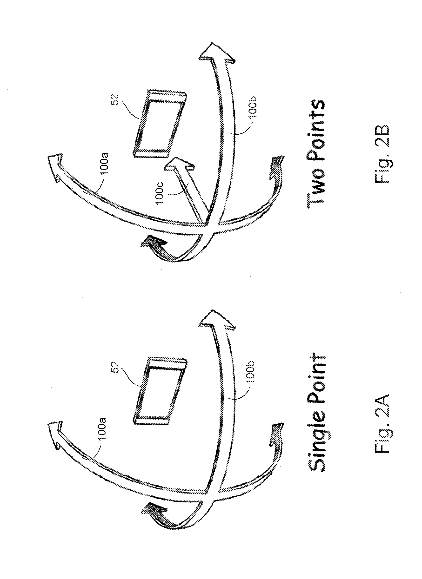
[0033] Number of Markers [0034] 1 point provides viewpoint movement along a spherical shell [0035] 2 markers provides position in 3D space of the viewpoint assuming eye is looking at the screen. [0036] >=3 points provide position in 3D space of the viewpoint as well as eye viewing orientation. [0037] 1 point provides the greatest physical presence as player normally moves head side to side to view an object or scene to understand the spatial structure. [0038] 2 point adds the ability to move viewpoint closer or further from the display assuming the eye remain looking at the display (reasonable assumption) [0039] 3 points provide viewpoint orientation. Game can become aware of player's viewing direction (e.g. other game characters might say "hey look at me")
[0040] Wearable Mount [0041] Hat [0042] Headband [0043] Glasses [0044] Anything wearable on head or even other part of the body represents possible mounting opportunity
[0045] Options [0046] Camera on head, marker on TV [0047] Multiple cameras to divide field of view
[0048] Other Tracking Technologies [0049] Magnetic [0050] Ultrasonic
Example Usage
[0051] Viewing:
[0052] The illusion of physical presence
[0053] Players natural movement as viewing input
[0054] Dodging
Game Character Awareness
[0055] E.g. Game character becoming aware when the player looks away
Physical Presence Visual Enhancement
[0056] These techniques maximize the 3D object's physical presence illusion: [0057] View point change results in view frustum change [0058] Objects modeled in real world coordinates and placed near the physical TV screen [0059] Increase parallax--introduce near field and far field objects in view to maximize parallax motion [0060] Enhance movement by scaling and offsets of marked points or marker placement [0061] 3D data can be modeled in real world space coordinates (e.g., a 3D character such as a football player can be 15'' tall placed near the plane of the display) [0062] As user eye position moves, appropriately rotate and translate in 3D characters to match the proper viewing from new eye position
BRIEF DESCRIPTION OF THE DRAWINGS
[0063] These and other features and advantages will be better and more completely understood by referring to the following detailed description of exemplary non-limiting illustrative embodiments in conjunction with the drawings of which:
[0064] FIG. 1 schematically shows an example non-limiting graphics display system including user tracking;
[0065] FIGS. 2A and 2B illustrate different example non-limiting tracking types;
[0066] FIGS. 3A-3C further illustrate example non-limiting tracking types;
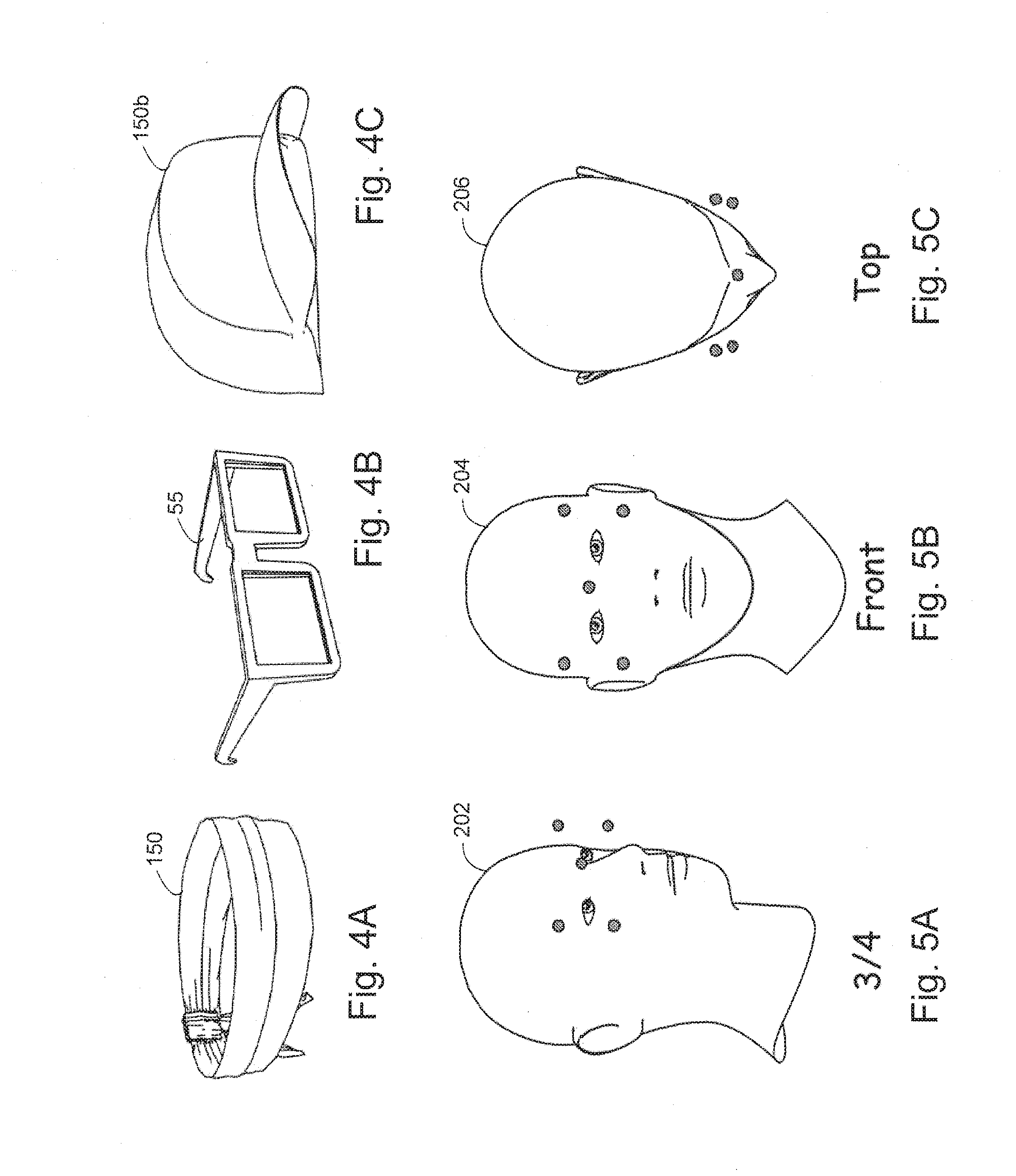
[0067] FIGS. 4A-4C illustrate example non-limiting headgear for tracking head position and movement;
[0068] FIGS. 5A-5C show example viewing frustum in front of a subject's eyes for different viewing directions;
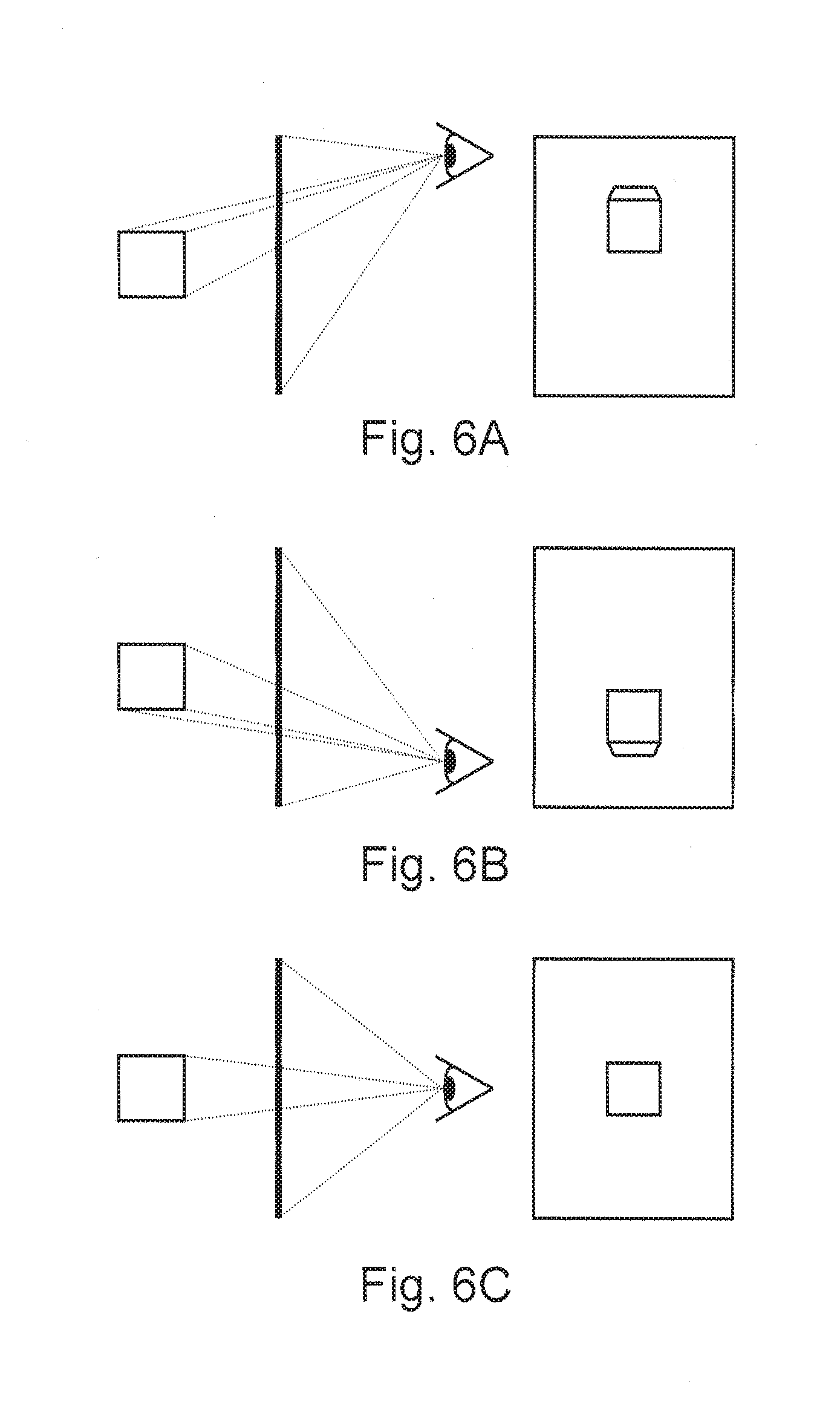
[0069] FIGS. 6A-6C show example graphics perspectives;
[0070] FIGS. 7A-7B show example images without 3-D enhancement but with parallax effects;
[0071] FIGS. 8A-8C show example images with 3-D enhancement;
[0072] FIG. 9 shows an example non-limiting software processing algorithm;
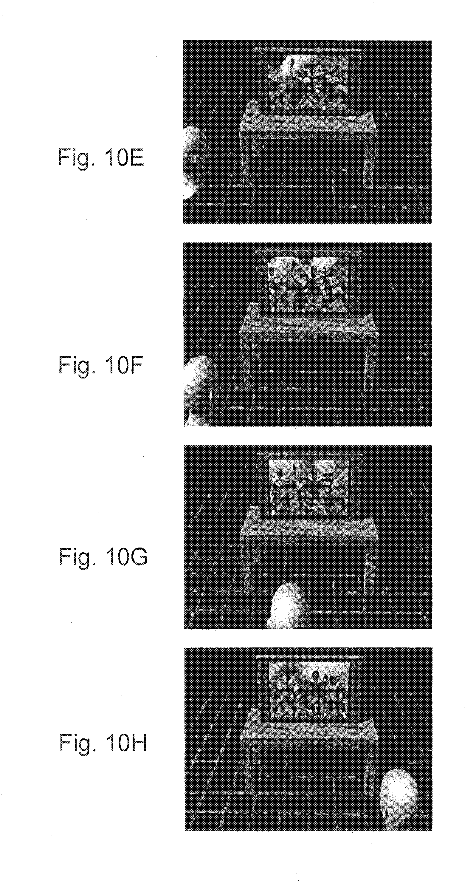
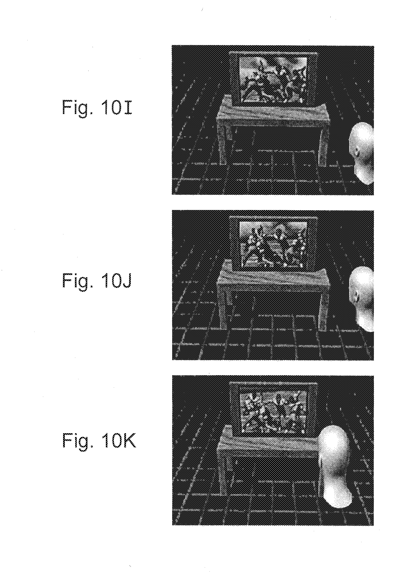
[0073] FIGS. 10A-10K show example third person images based on different head positions; and
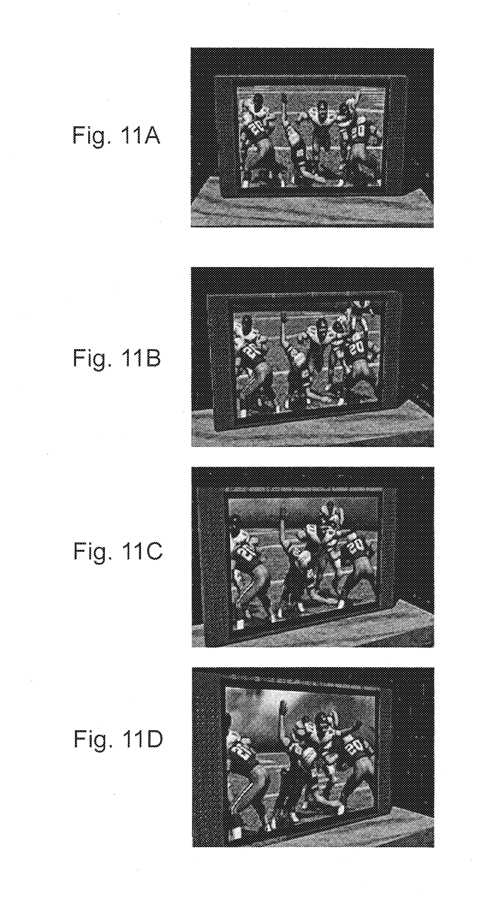
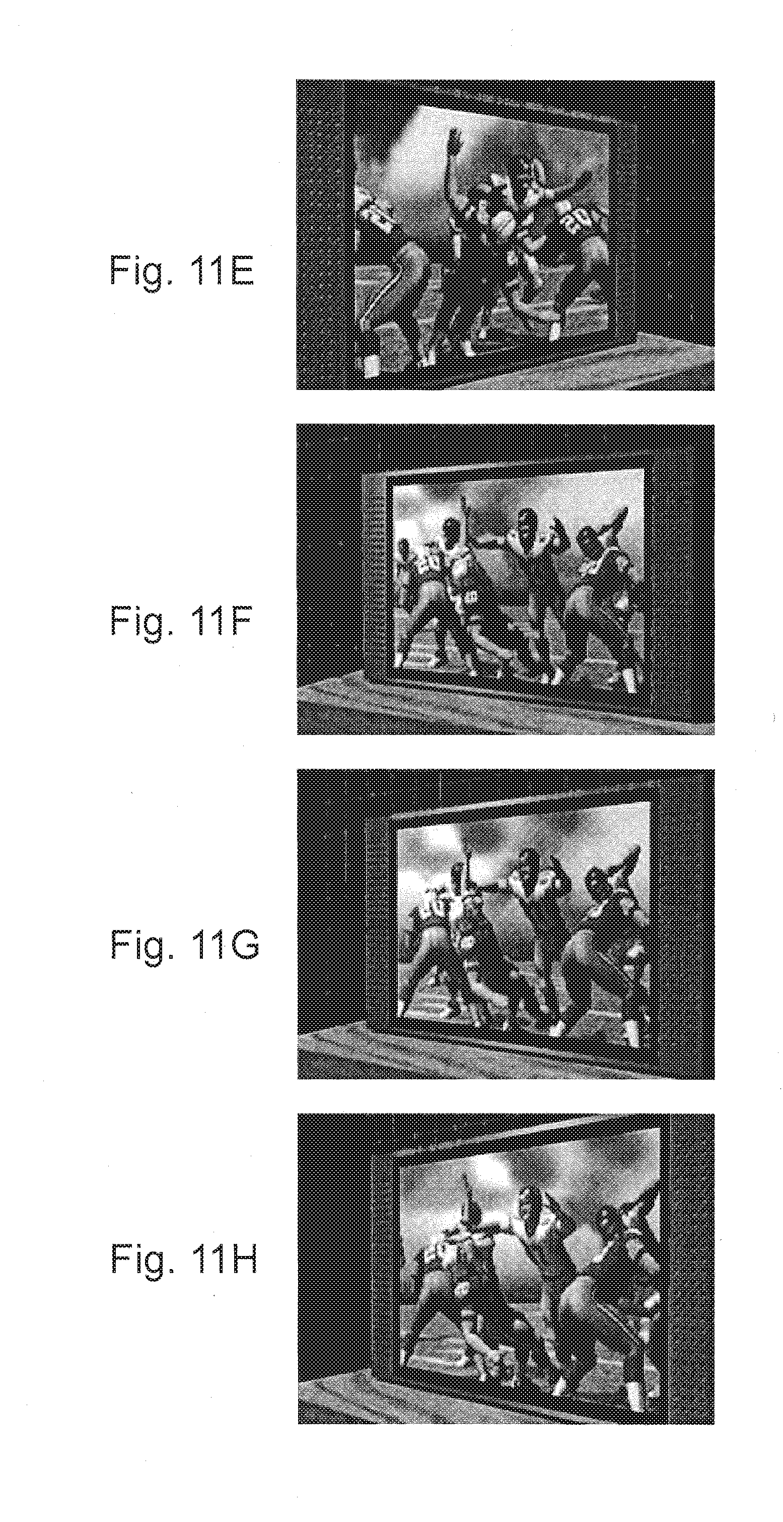
[0074] FIGS. 11A-11H show additional first person example non-limiting 3-D enhanced images.
DETAILED DESCRIPTION
[0075] FIG. 1 shows an example non-limiting 3D image display system 50 including a display device 52, an image generator 54, and a user tracking system 56a, 56b. User tracking system 56a, 56b determines the position of a person and/or the direction in which the person is looking, i.e. viewpoint. In response to the determined position and/or direction of the user's viewpoint, image generator 54 generates an image that appears three-dimensional to the person, i.e., the image appears to jump out of display 52 as if in three dimensions. As the user changes his viewpoint by turning his head and/or moving his head relative to display 52, image generator 54 adjusts the 3D perspective transformations applied to a 3D virtual world to generate new viewing perspectives that preserve and enhance the 3D effects.
[0076] In the example shown, image generator 54 can include any desired type of computing device such as for example a personal computer, video game console or handheld device, or any other suitable apparatus. In the example shown, image generator 54 includes a microprocessor 54a, a graphics processor 54b and a non-transitory storage device 54c. Storage device 54c in turn stores data and executable instructions 54d for execution by microprocessor 54 and/or graphics processor 54b. In one example non-limiting implementation, graphics processor 54b may comprise a conventional 3D graphics processor including for example the graphics capabilities of a Nintendo Wii, a Sony Playstation or Microsoft XBox video game console or any other desired graphics subsystem, graphics card or graphics pipeline.
[0077] In the example shown, image generator 54 produces an output 54e displayed by display device 52. In the example shown, display device 52 may comprise any conventional display device such as a television, an LCD or a plasma display panel, or any other suitable display device. Display 52 may for example comprise a conventional home television set that typically produces only 2D images.
[0078] It should be noted that in the context of the discussion herein, the term "3D image" does not mean merely an image that is generated based on a 3D virtual world. Rather, the image itself appears to be in three dimensions and as shown in FIG. 1, objects in the foreground appear to be projecting out of the plane of the 2D image device and into the actual three-dimensional world. Thus, the term "3D viewing" as used herein means "results in virtual objects appearing as if they occupy real world space." Such 3D viewing is generally not produced by conventional commercially available home video game systems at the time of this writing, but are instead typically available to the average consumer only through wearing 3D glasses at a movie theater, viewing a hologram, etc.
[0079] Thus, the technology provided by image generator 54 in conjunction with tracker 56a, 56b has the effect of transforming a conventional 2d display 52 into a 3D imaging system. The system 50 enables 3D viewing on a conventional 2D display 52 such as a television by tracking a person's viewpoint. Detecting a player's viewpoint movement to change the viewing of the displayed object(s) gives the illusion that the object is physically present in the 3D world as opposed to within or behind the screen of display 52. Properly matched geometry between virtual reality data and real world environment and proper movement according to a viewer's eye position/direction enables the brain to believe the object is floating in 3D space (stereo cues are unnecessary to provide this perception). The viewpoint movement detection provided by tracker 56a, 56b also provides enhanced features such as collision related game logic benefits including player dodging projectiles or other objects, a game character's ability to see the human player when not behind line of sight obstacles, etc.
[0080] System 50 thus enables physical presence on standard 2D displays such as a television 52 by tracking the viewpoint of the human viewer or game player. In one exemplary illustrative non-limiting implementation, tracker 56a, 56b provides a relatively wide field of view (FOV) in excess of 50 degrees so that the human viewer can move anywhere within a range of 100 degrees or more and tracking will continue to be successful. In addition, the graphics applications software 54d provided by system 50 can provide virtual object placement in such a way as to maximize parallax to enhance the effect of the virtual object being physically present in the actual 3D world.
[0081] In addition, exemplary illustrative non-limiting implementations of system 50 enable additional game play capability. In particular, moving the head and body to position the eye is a natural motion to see 3d objects. This movement can be used to dodge game objects, provide virtual game characters that are aware of a player's location and presence, etc.
[0082] In one example non-limiting implementation, a single point is sufficient to enable this dramatic effect. See for example FIGS. 2A and 3A which show that tracking a single point on the user is sufficient to determine the angle from the user to the center of the screen. Thus, in the example shown in FIG. 1, tracker 56a, 56b may comprise an imaging device such as an IR camera 56a that tracks an IR marker or emitter 56b disposed on or worn by the user. FIGS. 2A, 3A show that tracking one point provides viewpoint movement along a spherical shell, and may also provide the greatest physical presence as the player normally moves his head side to side to view an object or scene to understand the spatial structure.
[0083] In other implementations, tracking more points allows for additional capabilities. For example, FIGS. 2B and 3B show additional capabilities (distance) obtained by tracking two points. Two markers for example can provide position in 3D space of the viewpoint assuming the eye is looking at the display 52. Two points add the ability to move the viewpoint closer to or further away from the display 52 assuming the eye remains looking at the display (which is typically a reasonable assumption).
[0084] FIG. 3C shows still additional information (i.e., orientation) that can be obtained by tracking 3 points. Tracking three or more points provides position in 3D space of the viewpoint as well as eye viewing orientation. Three points thus provides viewer orientation that can be used for example to allow a game or other application to become aware of the player's viewing direction (e.g., to allow eye contact between a human player and a virtual player). The virtual character can for example detect when the human player is looking at him, and act accordingly.
[0085] While tracking additional points can have advantages, viewpoint determination based on tracking even a single point as shown in FIG. 1 is perhaps the most significant and can provide dramatic three-dimensional effects.
[0086] FIGS. 4A-4C show different non-limiting options for devices that can be worn on the head and can support a marker or emitter for tracking purposes. Such devices can include for example a hat, a headband, glasses, or anything that is wearable or supportable on the head or other part of the body to provide possible mounting opportunities. For camera based tracking, it is possible for example to wear a marker 56b on the head and provide a camera 56a in a stationary position such as on the display 52. A visible band light camera can be used in conjunction with face detection software to determine the location of the head and to extrapolate the position of the eyes. To improve detection, it is possible to decrease the signal-to-noise ratio by wearing a marker. In the case of an IR camera, the infrared spectrum detection can be enhanced by ignoring all visible spectrum. Infrared (IR) emitters such as IR LEDs can be used to illuminate a scene with retroreflector markers. An IR emitter can be worn directly as markers providing high signal-to-noise ratio. Other arrangements can include a camera on the player's head and a marker on the display 52 or other fixed location in the room, or multiple cameras or other imaging devices to divide the field of view. Ultrasonic, magnetic, electromagnetic or any other suitable tracking technology can be used.
[0087] In one example illustrative non-limiting implementation, it is possible to provide a wide field of view by enabling a larger viewpoint tracking range and providing a resulting increased freedom of user motion. Typical image cameras provide 50 degrees of field of view. It is desirable to achieve 110 degrees horizontal and 70 degree vertical field of view (see FIGS. 5A-5C--which show different potential marker positions).
[0088] FIGS. 6A-6C illustrate how image generator 54 can alter the perspective of a rendered image based on viewpoint. For example, FIG. 6A shows that a cube viewed from an angle above will reveal the front face of the cube plus a foreshortened perspective view of the top face; FIG. 6B shows that viewing the same cube from below reveals the front face plus a foreshortened perspective view of the bottom face; and FIG. 6C shows that viewing the cube head-on reveals the front face with no view of the top or bottom faces. Similar views can be generated for changes in viewpoint in the horizontal direction. Image generator 54 can automatically generate such images using conventional projection transformations as is well known to those skilled in the art. Generating images in real time response to information from tracker 56a, 56b can create an interesting dynamic three-dimensional effect.
[0089] FIG. 7A, 7B show conventional images from different viewpoints when watching a conventional 2D image generator but providing different parallax distortion to create 3D effects. As explained above, parallax can be used to enhance the 3D viewing herein. FIGS. 8A-8C show 3D imaging effects from different viewpoints.
[0090] FIG. 9 shows example software processing for the FIG. 1 system. In the example shown, block 302 obtains the camera image from tracker 56a. The processor 54a executing instructions 54d from non-transitory storage device 54c determines the number of viewpoints (block 304) and then performs an enhanced viewpoint movement operation (block 306). The EnhanceViewpointMovement can optically increase the scale or offset of the actual player's movement to enhance the physical presence illusion. Data can be provided in polar coordinates to provide easy conversion to Cartesian coordinate space.
[0091] In one example implementation, an EvaluateCollision function (block 308) keeps the viewpoint from entering inside of objects. ChangeViewFrustum (block 310) changes the viewing frustum on the display to reflect to viewpoint movement. In one example non-limiting implementation, viewpoint changes result in view frustum changes, and objects having 3D data modeled in real world coordinates are placed near the physical television screen so they can be imaged in a way that appears to jump out of the screen. Head (eye position and direction) tracking provides input to change 3D data display according to viewpoint. One determination can be to process camera images to find the "center" position of the IR emitter. Increased parallax can be used to introduce near field and far field objects in view to maximize parallax motion. Tracking movement is enhanced by scaling and offsets of marked points or marker placement.
[0092] Meanwhile, game logic (block 312) is used to animate the displayed objects to provide full realistic motion of objects that appear to jump out of the display screen 52.
[0093] FIGS. 10A-10K show example 3D effects (third person view) along with the position of the viewer's head changing relative to the display 52. FIGS. 11A-11H show example first person views of different 3D images as viewpoint changes. FIGS. 11A-11H are taken from a movie that shows remarkable 3D viewing effects as the viewpoint changes. The 3D viewing effects may be hard to see in these patent drawings, but they are easy to discern in the actual viewing experience. For example, FIG. 11A (straight on) appears relatively 2D as might be expected, but changing the viewpoint to the left to result in the FIG. 11B, 11C, 11D drawings causes 3D viewing effects to become clear and distinct. Animation of such figures to provide motion (as opposed to still or stop action) makes the 3D viewing effects become very clear and remarkable. For this reason, a particularly useful feature of the technology herein is in connection with video games or other simulations that provide rapidly changing images. As the viewpoint changes, the system 50 re-renders the scene in real time from the new viewpoint to provide highly realistic 3D viewing. It appears that the football players are popping out of the display and occupy the real world. The effect is especially pronounced for objects in the foreground. For example, the arms and helmet of the player who is falling in FIGS. 11B-11D appears to be falling out of the television set and into the real world. Similarly, tackler 87 appears to be lunging out of the television set and into the real world. FIGS. 11A-11H show images generated with a still or static scene that is re-rendered at a relatively rapid rate (e.g., 30 or 60 frames per second) for a new perspective based on changing viewpoint. However, the scene could of course be animated and changing in real time based on game play or simulation for example, and at the same time the scene can be re-rendered from different viewpoints in real time based on changing tracking information. The overall effect provides highly interesting and exciting 3D imaging that maintains the user's interest.
[0094] In some implementations, the tracking information is not captured in real time but rather is stored and played back (or simulated) to provide a simulated change in viewpoint. Thus, the 3D viewing effects are discernable not just by the person whose viewpoint is being tracked, but others who are also watching (see FIG. 10A et seq.). Of course, if the 3D image changes its perspective in real time response to a particular user's change of viewpoint, the result to that user can approach virtual reality.
[0095] Dodging is possible by for example imaging 3D projectiles that fly toward the user. Using the 3D viewing effects described herein, the projectiles can appear to be flying out of the display toward the user. If the projectiles respond in real time to change in user viewpoint and/or position, the user can feel as if she is avoiding or dodging the projectiles. In one example non-limiting scenario, the projectiles preferably are imaged so that they appear to be elongated by the speed at which they are travelling, thereby providing a 3D effect as they appear to "pass" the user.
[0096] Further example enhancements:
[0097] Augmented Reality. Some synthetic picture intermixed with the real world can be used. This is a quick and realistic possibility to e.g., project certain types of images such as robots or to play a chess game. If we can locate in the real world where a planar surface is, we could each look through this object and see the same virtual object augmented into the real world. A display that is 50% real world, 50% synthetic, with positioning techniques and way to possibly detect motion or position is possible.
[0098] It is possible to use goggles to accommodate eye glasses. If used, then it is possible to handle see-through. An alternative is to capture the real world with a camera. Resolution is less, but we get the benefit of providing a hyper stereo view and enhancement of real world view.
[0099] It is possible to Invite your Curiosity by displaying the "inside" image on a screen that everyone could see. One way: cupped mirror could be half-reflective, one-way so observers can see an image of what the user is seeing. This gets a larger group involvement. Another way is to provide multiple head sets.
[0100] Enhancing the VR Experience Additional output devices that enhance the experience can be provided. For example, we can put light out that is correlated to the image to provide "ultra wide field of view correlated lighting." Given that your eye does not see clearly in the periphery, this could still be useful and interesting.
[0101] Additionally, smell is a very strong sense. There may be some ways to produce aromas for a very strong experience.
[0102] Virtual wind could enhance the experience.
[0103] Temperature: blowing cool air on your face.
[0104] Physiologically comfortable stereo viewing is a way to prevent headaches. If you find a little spec on your windshield, focus on that and then far field and then back again. Eye strain happens quite quickly. Lots of folks in the past require the users to focus far field and close up, but this can cause headaches. We can stay on one side of the focal point cone, to provide higher level of comfort.
[0105] Detect Emotions via monitoring mental state. Brain wave detection, detect eye movement, heart rate monitor or the like can be used. If we provide goggles, we can also provide detectors (electrodes) fairly easily.
[0106] Shroud Possible to filtering out the real world by using a shroud
[0107] While the technology herein has been described in connection with exemplary illustrative non-limiting embodiments, the invention is not to be limited by the disclosure. The invention is intended to be defined by the claims and to cover all corresponding and equivalent arrangements whether or not specifically disclosed herein.
* * * * *
D00000
D00001
D00002
D00003
D00004
D00005
D00006
D00007
D00008
D00009
D00010
D00011
D00012
D00013
XML
uspto.report is an independent third-party trademark research tool that is not affiliated, endorsed, or sponsored by the United States Patent and Trademark Office (USPTO) or any other governmental organization. The information provided by uspto.report is based on publicly available data at the time of writing and is intended for informational purposes only.
While we strive to provide accurate and up-to-date information, we do not guarantee the accuracy, completeness, reliability, or suitability of the information displayed on this site. The use of this site is at your own risk. Any reliance you place on such information is therefore strictly at your own risk.
All official trademark data, including owner information, should be verified by visiting the official USPTO website at www.uspto.gov. This site is not intended to replace professional legal advice and should not be used as a substitute for consulting with a legal professional who is knowledgeable about trademark law.