Pumping System Shaft Conversion Adapter
Ashurst; Joseph ; et al.
U.S. patent application number 16/040487 was filed with the patent office on 2019-01-24 for pumping system shaft conversion adapter. This patent application is currently assigned to GE Oil & Gas ESP, Inc.. The applicant listed for this patent is GE Oil & Gas ESP, Inc.. Invention is credited to Joseph Ashurst, Blair Ellington, Andrew Roberts, Matthew Schoelen.
| Application Number | 20190024665 16/040487 |
| Document ID | / |
| Family ID | 65015608 |
| Filed Date | 2019-01-24 |


| United States Patent Application | 20190024665 |
| Kind Code | A1 |
| Ashurst; Joseph ; et al. | January 24, 2019 |
Pumping System Shaft Conversion Adapter
Abstract
A pump for use in a motorized pumping system has a pump shaft with a lower ring groove and an upper ring groove. The pump also includes a lower adapter and an upper adapter. The lower adapter has a pair of lower ring halves configured to fit within the lower ring groove and the upper adapter has a pair of upper ring halves configured to fit within the upper ring groove. The pump further includes a plurality of stages that each have a stationary diffuser and a rotating impeller. The rotating impellers are connected to the shaft with a keyed connection that permits the impeller to axially travel along the shaft. Also disclosed is a method for converting a compression shaft to a floater shaft that includes the steps of placing an upper adapter into the upper ring groove, placing one or more impellers on the shaft, placing one or more standard spacers on the shaft and placing a lower adapter into the lower ring groove.
| Inventors: | Ashurst; Joseph; (Oklahoma City, OK) ; Roberts; Andrew; (Jacksonville, FL) ; Ellington; Blair; (Oklahoma City, OK) ; Schoelen; Matthew; (Norman, OK) | ||||||||||
| Applicant: |
|
||||||||||
|---|---|---|---|---|---|---|---|---|---|---|---|
| Assignee: | GE Oil & Gas ESP, Inc. Oklahoma City OK |
||||||||||
| Family ID: | 65015608 | ||||||||||
| Appl. No.: | 16/040487 | ||||||||||
| Filed: | July 19, 2018 |
Related U.S. Patent Documents
| Application Number | Filing Date | Patent Number | ||
|---|---|---|---|---|
| 62535224 | Jul 20, 2017 | |||
| Current U.S. Class: | 1/1 |
| Current CPC Class: | F04D 29/054 20130101; F04D 29/042 20130101; F04D 29/628 20130101; F04D 1/063 20130101; F04D 1/06 20130101; F04D 29/047 20130101; E21B 43/128 20130101; F04D 13/10 20130101 |
| International Class: | F04D 13/10 20060101 F04D013/10; F04D 1/06 20060101 F04D001/06; F04D 29/054 20060101 F04D029/054 |
Claims
1. A pump for use in a motorized pumping system, the pump comprising: a shaft, wherein the shaft includes a lower ring groove and an upper ring groove; a lower adapter, wherein the lower adapter comprises a pair of lower ring halves configured to fit within the lower ring groove; an upper adapter, wherein the upper adapter comprises a pair of upper ring halves configured to fit within the upper ring groove; a plurality of stages, wherein each of the plurality of stages comprises: a stationary diffuser; and a rotating impeller connected to the shaft with a keyed connection that permits the impeller to axially travel along the shaft.
2. The pump of claim 1, wherein the lower adapter further comprises a lower adapter snap ring configured to hold the pair of lower ring halves together in the lower ring groove.
3. The pump of claim 1, wherein the upper adapter further comprises an upper adapter snap ring configured to hold the pair of upper ring halves together in the upper ring groove.
4. The pump of claim 1, wherein the lower adapter comprises a lower adapter shoulder that has an adapter shoulder outer diameter.
5. The pump of claim 4, further comprising a lower bearing that has an inner diameter that is larger than the adapter shoulder outer diameter.
6. The pump of claim 5, wherein the lower bearing support comprises a bearing pad.
7. The pump of claim 6, further comprising a bearing spacer connected to the shaft and configured to contact the bearing pad of the lower bearing support.
8. A submersible pumping system comprising: an electric motor; a seal section; and a multistage centrifugal pump driven by the motor, wherein the pump comprises: a shaft, wherein the shaft includes a lower ring groove and an upper ring groove; a lower adapter, wherein the lower adapter comprises a pair of lower ring halves configured to fit within the lower ring groove; an upper adapter, wherein the upper adapter comprises a pair of upper ring halves configured to fit within the upper ring groove; and a plurality of stages, wherein each of the plurality of stages comprises: a stationary diffuser; and a rotating impeller connected to the shaft with a keyed connection that permits the impeller to axially travel along the shaft.
9. The submersible pumping system of claim 8, wherein the lower adapter further comprises a lower adapter snap ring configured to hold the pair of lower ring halves together in the lower ring groove.
10. The submersible pumping system of claim 8, wherein the upper adapter further comprises an upper adapter snap ring configured to hold the pair of upper ring halves together in the upper ring groove.
11. The submersible pumping system of claim 8, wherein the lower adapter comprises a lower adapter shoulder that has an adapter shoulder outer diameter.
12. The submersible pumping system of claim 11, further comprising a lower bearing that has an inner diameter that is larger than the adapter shoulder outer diameter.
13. The submersible pumping system of claim 12, wherein the lower bearing support comprises a bearing pad.
14. The submersible pumping system of claim 13, further comprising a bearing spacer connected to the shaft and configured to contact the bearing pad of the lower bearing support.
15. The submersible pumping system of claim 8, wherein the shaft does not include any ring grooves other than the lower ring groove and the upper ring groove
16. A method for converting a compression shaft to a floater shaft, wherein the compression shaft includes an upper ring groove and a lower ring groove that are respectively capable of holding an upper two-piece ring and a lower two-piece ring to apply compression to a diffuser stack disposed along the compression shaft, the method comprising the steps of: placing an upper adapter into the upper ring groove; placing one or more impellers on the shaft; placing one or more standard spacers on the shaft; and placing a lower adapter into the lower ring groove.
17. The method of claim 16, further comprising the step of placing one or more bearing spacers on the shaft before the step of placing a lower adapter into the lower ring groove.
18. The method of claim 16, wherein the step of placing an upper adapter into the upper ring groove further comprises: placing a first upper ring half into the upper ring groove; placing a second upper ring half into the upper ring groove; and securing the first and second upper ring halves together.
19. The method of claim 18, wherein the step of securing the first and second upper ring halves together further comprises placing an upper adapter snap ring over the first and second upper ring halves.
20. The method of claim 16, wherein the step of placing a lower adapter into the lower ring groove further comprises: placing a first lower ring half into the lower ring groove; placing a second lower ring half into the lower ring groove; and securing the first and second lower ring halves together.
Description
RELATED APPLICATIONS
[0001] This application claims the benefit of U.S. Provisional Patent Application Ser. No. 62/535,224 filed Jul. 20, 2017 entitled "Pumping System Shaft Conversion Adapter," the disclosure of which is herein incorporated by reference.
FIELD OF THE INVENTION
[0002] This invention relates generally to the field of submersible pumping systems, and more particularly, but not by way of limitation, to a mechanism for converting shafts used in multistage centrifugal pumps.
BACKGROUND
[0003] Multistage centrifugal pumps are used in a variety of submersible and surface-based applications. In these pumps, each "stage" includes a rotating impeller and a stationary diffuser. A shaft keyed only to the impellers transfers mechanical energy from the motor. During use, the rotating impeller imparts kinetic energy to the fluid. A portion of the kinetic energy is converted to pressure as the fluid passes through the downstream diffuser. As the fluid is pressurized and moved through the pump, force pushes against the impellers in the opposite direction. This force is generally referred to as "down thrust." "Up-thrust" occurs as fluid moving through the impeller pushes the impeller upward. Centrifugal pumps have a flow rate equilibrium point where the up thrust and down thrust generated by the impellers are balanced. Lower flow rates cause excess down thrust, while higher flow rates may cause excess up thrust. To prevent damage to the pump, the up thrust and down thrust must be controlled using one or more thrust bearings.
[0004] In many multistage pumps, the impellers are placed onto the pump shaft and compressed between a pair of two-piece rings located at opposite ends of the pump shaft. This design is often referred to as a "fixed impeller" pump and the thrust generated by the collection of impellers is transferred to the "compression shaft" through the lower two-piece ring. The thrust is carried by the compression shaft into a large thrust bearing that is often located in a seal section that is adjacent to the pump.
[0005] In some cases, it is desirable to use a "floating impeller" design in which the impellers are not all linked together under compression. In a floating impeller design, the impellers are allowed to move in an axial direction along the shaft during operation and the down thrust generated by the impellers is not transferred through the shaft to a dedicated thrust bearing. Instead, the down thrust created by the impellers is offset by "bearing stages" positioned at intervals within the pump. The impellers must be free to move independently between bearing stages to transfer the thrust to the bearing stages.
[0006] A standard "floater" shaft utilizes snap rings to hold the impellers, spacers and other components to the shaft and allow for free axial movement of the impellers. Existing floater shafts thus include specific grooves at specified locations on the shaft to accommodate the snap rings. These grooves are not typically present on a compression shaft. Efforts to retrofit compression shafts to accommodate a floating impeller design are expensive and time consuming because the snap ring grooves must be added to the compression shaft. There is, therefore, a need to develop an adapter system that permits the facilitated conversion of a compression shaft into a floater shaft. It is to these and other objects that the present invention is directed.
SUMMARY OF THE INVENTION
[0007] In one aspect, embodiments of the present invention include a pump for use in a motorized pumping system. The pump includes a shaft that has a lower ring groove and an upper ring groove. The pump also includes a lower adapter and an upper adapter. The lower adapter has a pair of lower ring halves configured to fit within the lower ring groove and the upper adapter has a pair of upper ring halves configured to fit within the upper ring groove. The pump further includes a plurality of stages that each have a stationary diffuser and a rotating impeller. The rotating impellers are connected to the shaft with a keyed connection that permits the impeller to axially travel along the shaft.
[0008] In another aspect, an embodiment of the invention includes a method for converting a compression shaft to a floater shaft, where the compression shaft includes an upper ring groove and a lower ring groove that are respectively capable of holding an upper two-piece ring and a lower two-piece ring to apply compression to an impeller stack disposed along the compression shaft. The method includes the steps of placing an upper adapter into the upper ring groove, placing one or more impellers on the shaft, placing one or more standard spacers on the shaft and placing a lower adapter into the lower ring groove.
BRIEF DESCRIPTION OF THE DRAWINGS
[0009] FIG. 1 is an elevational view of a submersible pumping system.
[0010] FIG. 2 is a cross-sectional view of the pump from the submersible pumping system of FIG. 1.
[0011] FIG. 3 is a close-up, cross-sectional view of several stages from the pump of FIG. 2.
[0012] FIG. 4 is a close-up, perspective, cross-sectional view of the upper adapter near the head of the pump.
[0013] FIG. 5 is a cross-sectional view of the head of the pump with upper adapter.
[0014] FIG. 6 is a close-up, perspective, cross-sectional view of the lower adapter in the base of the pump.
[0015] FIG. 7 is a cross-sectional view of the base of the pump with the lower adapter.
[0016] FIG. 8 is a close-up, cross-sectional view of the upper adapter.
[0017] FIG. 9 is a close-up, cross-sectional view of the lower adapter.
[0018] FIG. 10 is a perspective view of the lower adapter.
WRITTEN DESCRIPTION
[0019] FIG. 1 shows an elevational view of a pumping system 100 attached to production tubing 102. The pumping system 100 and production tubing 102 are disposed in a wellbore 104, which is drilled for the production of a fluid such as water or petroleum. As used herein, the term "petroleum" refers broadly to all mineral hydrocarbons, such as crude oil, gas and combinations of oil and gas. The production tubing 102 connects the pumping system 100 to a wellhead 106 located on the surface. Although the pumping system 100 is primarily designed to pump petroleum products, it will be understood that the present invention can also be used to move other fluids. It will also be understood that, although each of the components of the pumping system are primarily disclosed in a submersible application, some or all of these components can also be used in surface pumping operations.
[0020] It will be noted that although the pumping system 100 is depicted in a vertical deployment in FIG. 1, the pumping system 100 can also be used in non-vertical applications, including in horizontal and non-vertical wellbores 104. Accordingly, references to "upper" and "lower" within this disclosure are merely used to describe the relative positions of components within the pumping system 100 and should not be construed as an indication that the pumping system 100 must be deployed in a vertical orientation.
[0021] The pumping system 100 includes a pump 108, a motor 110 and a seal section 112. In some embodiments, the motor 110 is an electrical motor that receives power from a surface-mounted motor control unit (not shown). When energized, the motor 110 drives a shaft that causes the pump 108 to operate. The seal section 112 provides for the expansion of motor lubricants during operation while isolating the motor 110 from the wellbore fluids passing through the pump 108. Although only one of each component is shown, it will be understood that more can be connected when appropriate. It may be desirable to use tandem-motor combinations, multiple seal sections, multiple pump assemblies or other downhole components not shown in FIG. 1. For example, in certain applications it may be desirable to place a seal section 112 below the motor 110.
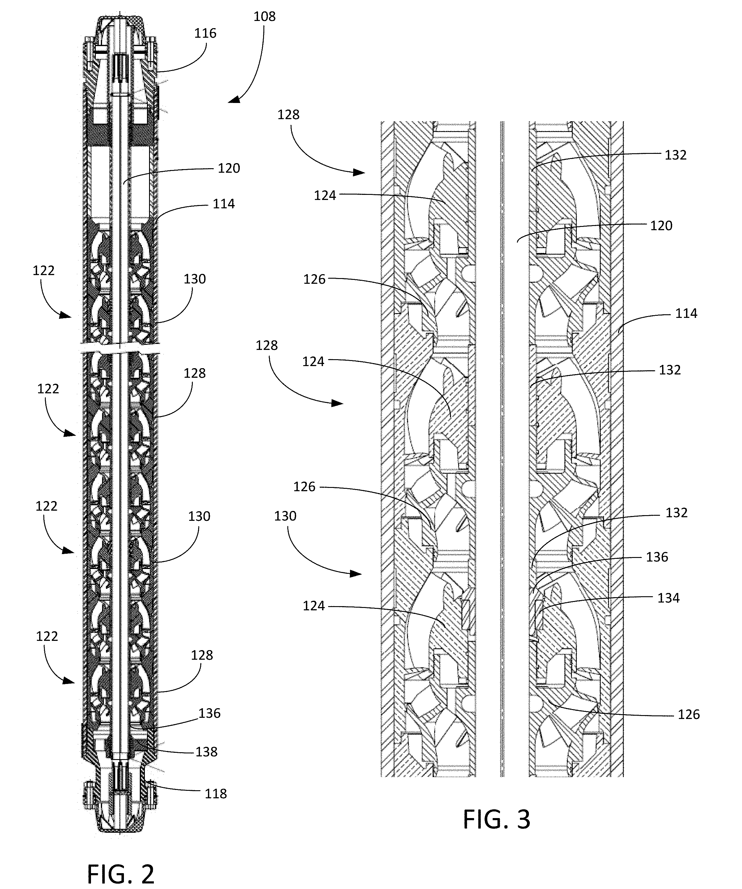
[0022] Turning to FIG. 2, shown therein is a cross-sectional view of the pump 108. The pump 108 includes a pump housing 114, a head 116, a base 118, a shaft 120, and a plurality of stages 122. As shown in the close-up view of FIG. 3, each of the plurality of stages 122 includes a diffuser 124 and an impeller 126. The impellers 126 are connected to the shaft 120 with a keyed connection that permits axial movement of the impeller 126 along the shaft 120. In this way, the impellers 126 are permitted a limited amount of axial "float" between adjacent diffusers 124.
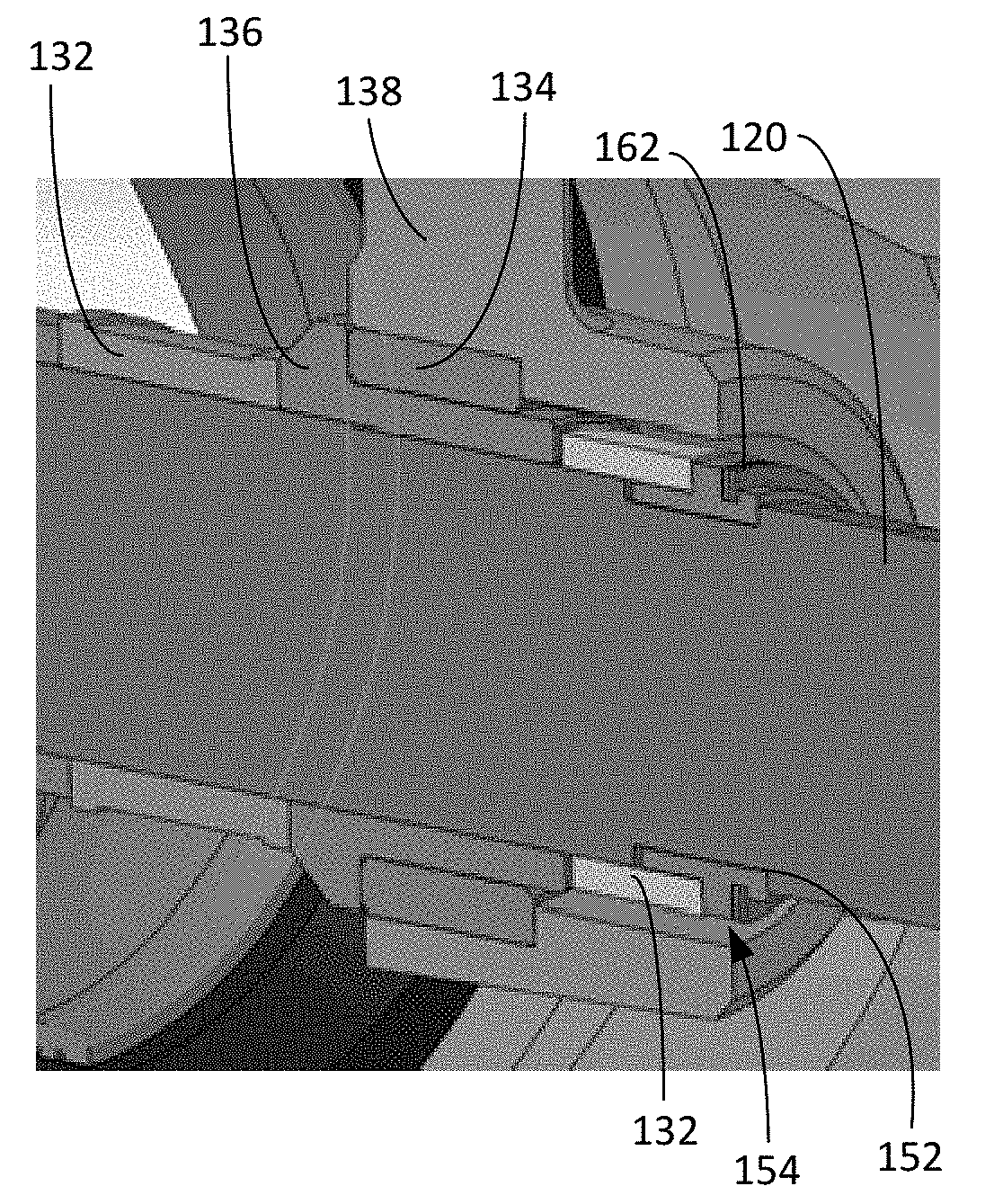
[0023] As illustrated in FIG. 3, the stages 122 in the pump 108 are configured as either floating stages 128 or bearing stages 130. In each floating stage 128, the impeller 126 transfers hydraulic load to the lower or upstream impeller 126 through a standard spacer 132 that passes through the diffuser 124 without interference or contact. In each bearing stage 130, the impeller 126 transfers down thrust through a spacer 132 to a bearing spacer 136 by contact with a bearing pad 134 in the adjacent diffuser 124. In this way, the hydraulic load created by a collection of impellers 126 is transferred into a diffuser 124 in a bearing stage 130. It will be appreciated that some or all of the stages 122 can be configured as a bearing stage 130. As illustrated in FIGS. 2, 6, and 7, the pump 108 may also include a separate lower bearing support 138 that includes a bearing pad 134 that offsets thrust carried through a bearing spacer 136.
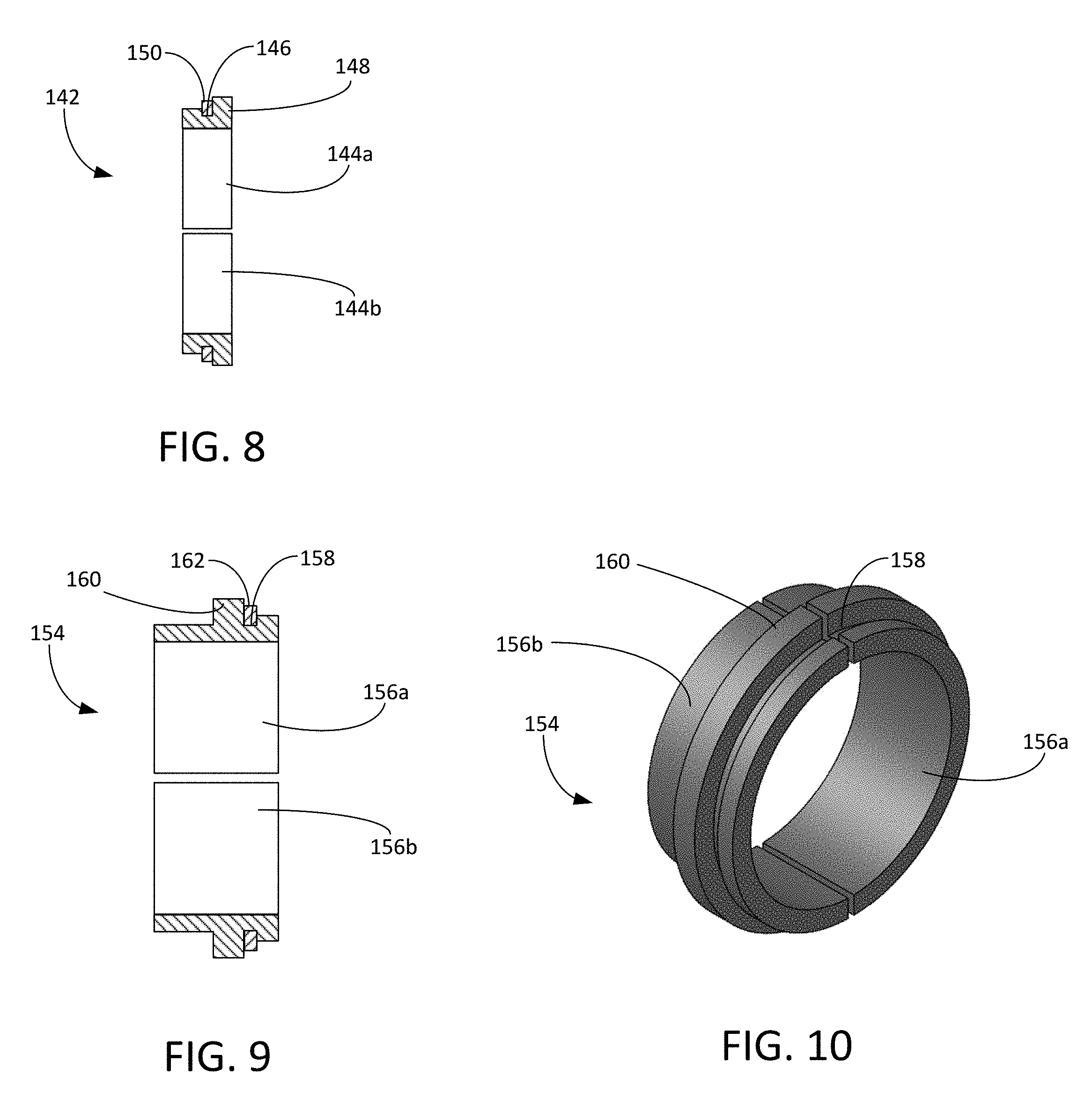
[0024] Turning to FIGS. 4 and 5, shown therein are close-up, cross-sectional views of a portion of the upper end of the pump 108. The shaft 120 includes a standard upper ring groove 140 that is configured to accept a conventional two-piece ring (not shown), which would be used in a fixed impeller pump to capture the compression within the impeller stack. The two-piece ring has been replaced with an upper adapter 142 for the floating impeller design of the pump 108. A close-up, cross-sectional view of upper adapter 142 is shown in FIG. 8. The upper adapter 142 includes two upper ring halves 144a, 144b. Each of the two upper ring halves 144a, 144b has a width that is configured to fit tightly within the upper ring groove 140. Each of the upper ring halves 144a, 144b further includes an upper adapter snap ring groove 146 and an upper adapter shoulder 148.
[0025] During assembly, the two upper ring halves 144a, 144b are placed into the upper ring groove 140 and approximated. An upper adapter snap ring 150 can then be placed into the upper adapter snap ring groove 146 to hold the two upper ring halves 144a, 144b together within the upper ring groove 140. In other embodiments, set screws or clamps are used to hold the two upper ring halves 144a, 144b together. Once assembled, the upper adapter 142 remains fixed with the shaft 120 to contain and position the standard spacers 132 and impellers 126 as they are allowed to move axially along the shaft 120. The upper adapter 142 provides a stop and upper limit for the upward, downstream displacement of the top impeller 126 and spacers 132.
[0026] Turning to FIGS. 6 and 7, shown therein are close-up, cross-sectional views of the lower end of the pump 108. The shaft 120 includes a lower ring groove 152 that is configured to accept a conventional two-piece ring (not shown) that would be used in a fixed impeller pump to capture the compression within the impeller stack. The two-piece ring has been replaced with a lower adapter 154 for the floating impeller design of the pump 108. Cross-sectional and perspective views of lower adapter 154 are shown in FIGS. 9 and 10, respectively. The lower adapter 154 includes two lower ring halves 156a, 156b. Each of the two lower ring halves 156a, 156b has a width that is configured to fit tightly within the lower ring groove 152. Each of the lower ring halves 156a, 156b further includes a lower adapter snap ring groove 158 and a lower adapter shoulder 160.
[0027] During assembly, the two lower ring halves 156a, 156b are placed into the lower ring groove 152 and approximated. A lower adapter snap ring 162 can then be placed into the lower adapter snap ring groove 158 to hold the two lower ring halves 156a, 156b together within the lower ring groove 152. In other embodiments, set screws or clamps are used to hold the two lower ring halves 156a, 156b together. Once assembled, the lower adapter 154 remains fixed with the shaft 120 to contain and position the standard spacers 132 and impellers 126 as they are allowed to move axially along the shaft 120.
[0028] As best illustrated in FIG. 6, the lower adapter 154 can be used in combination with the lower bearing support 138 to offset down thrust carried along the shaft 120 while permitting the shaft 120 to lift downstream in the event the up thrust forces exceed the down thrust forces. The outer diameter of the lower adapter 154 is smaller than the inner diameter of the lower bearing support 138. This clearance allows the lower adapter 154 to move inside the lower bearing support 138, where the lower adapter should 160 can push the bearing spacer 136 and any standard spacers 132 downstream along the shaft 120 within the tolerances provided by the spaces between the various components connected to the shaft 120.
[0029] Thus, the upper adapter 142 and lower adapter 154 provide an efficient mechanism for positioning and retaining the standard spacers 132, bearing spacers 136, impellers 126 and other components disposed along the outside of the shaft 120. The upper adapter 142 and lower adapter 154 permit the conversion of a conventional compression shaft into a "floater" shaft without additional machining operations to the shaft 120. The ability to quickly and easily convert a compression shaft into a floater shaft reduces inventory demands and improves part interchangeability. Shafts removed from older fixed impeller pumps can be easily reclaimed, converted and installed in a floating impeller pump with the upper and lower adapters 142, 154.
[0030] It is to be understood that even though numerous characteristics and advantages of various embodiments of the present invention have been set forth in the foregoing description, together with details of the structure and functions of various embodiments of the invention, this disclosure is illustrative only, and changes may be made in detail, especially in matters of structure and arrangement of parts within the principles of the present invention to the full extent indicated by the broad general meaning of the terms in which the appended claims are expressed. It will be appreciated by those skilled in the art that the teachings of the present invention can be applied to other systems without departing from the scope and spirit of the present invention.
* * * * *
D00000
D00001
D00002
D00003
D00004
XML
uspto.report is an independent third-party trademark research tool that is not affiliated, endorsed, or sponsored by the United States Patent and Trademark Office (USPTO) or any other governmental organization. The information provided by uspto.report is based on publicly available data at the time of writing and is intended for informational purposes only.
While we strive to provide accurate and up-to-date information, we do not guarantee the accuracy, completeness, reliability, or suitability of the information displayed on this site. The use of this site is at your own risk. Any reliance you place on such information is therefore strictly at your own risk.
All official trademark data, including owner information, should be verified by visiting the official USPTO website at www.uspto.gov. This site is not intended to replace professional legal advice and should not be used as a substitute for consulting with a legal professional who is knowledgeable about trademark law.