Pneumatic Pulsation Liquid Color Pumping
MAGUIRE; Stephen B.
U.S. patent application number 16/144522 was filed with the patent office on 2019-01-24 for pneumatic pulsation liquid color pumping. The applicant listed for this patent is Stephen B. MAGUIRE. Invention is credited to Stephen B. MAGUIRE.
| Application Number | 20190024653 16/144522 |
| Document ID | / |
| Family ID | 53797695 |
| Filed Date | 2019-01-24 |


| United States Patent Application | 20190024653 |
| Kind Code | A1 |
| MAGUIRE; Stephen B. | January 24, 2019 |
PNEUMATIC PULSATION LIQUID COLOR PUMPING
Abstract
A liquid color pump and method for operation thereof includes a diaphragm displaceable into a chamber to displace liquid color therefrom; a pair of solenoid valves, each having an inlet port, an exhaust port, and first and second output ports; a potentiometer sensing displacement position of the diaphragm and a processor actuating the solenoid valves responsively to a diaphragm position sensed by the potentiometer.
| Inventors: | MAGUIRE; Stephen B.; (West Chester, PA) | ||||||||||
| Applicant: |
|
||||||||||
|---|---|---|---|---|---|---|---|---|---|---|---|
| Family ID: | 53797695 | ||||||||||
| Appl. No.: | 16/144522 | ||||||||||
| Filed: | September 27, 2018 |
Related U.S. Patent Documents
| Application Number | Filing Date | Patent Number | ||
|---|---|---|---|---|
| 14700911 | Apr 30, 2015 | |||
| 16144522 | ||||
| 13913375 | Jun 7, 2013 | 9188118 | ||
| 14700911 | ||||
| 14168731 | Jan 30, 2014 | |||
| 14700911 | ||||
| 14587921 | Dec 31, 2014 | 9599265 | ||
| 14168731 | ||||
| 14617035 | Feb 9, 2015 | 9637283 | ||
| 14587921 | ||||
| 15298802 | Oct 20, 2016 | |||
| 14617035 | ||||
| 61986293 | Apr 30, 2014 | |||
| 61660326 | Jun 15, 2012 | |||
| Current U.S. Class: | 1/1 |
| Current CPC Class: | F04B 49/06 20130101; F04B 51/00 20130101; F04B 53/1082 20130101; F04B 49/22 20130101; F04B 43/02 20130101; F04B 43/0733 20130101; F04B 43/028 20130101 |
| International Class: | F04B 43/073 20060101 F04B043/073; F04B 49/06 20060101 F04B049/06; F04B 49/22 20060101 F04B049/22; F04B 43/02 20060101 F04B043/02; F04B 51/00 20060101 F04B051/00 |
Claims
1. A liquid color pump comprising: a) a diaphragm displaceable into a chamber to displace liquid color therefrom; b) a pair of solenoid valves, each having an inlet port, an exhaust port, a first output port connecting to the inlet port when the valve is energized, and a second output port connecting to the inlet port when the valve is not energized; i) a first one of the valves having its inlet port connected to a compressed air supply, its first output port connected to the diaphragm, its second output port blocked, and its exhaust port connected to the inlet port of the second valve; ii) the second valve having its first output port connected to atmosphere; c) a potentiometer sensing displacement position of the diaphragm; and d) a processor actuating the solenoid valves responsively to diaphragm position sensed by the potentiometer.
2. A liquid color pump comprising: a) a diaphragm displaceable into a chamber for displacing liquid color therefrom; b) a pair of solenoid valves, each valve having an inlet port, an exhaust port, and an output port connected to the inlet port when the valve is energized, and connected to the exhaust port when the valve is not energized; i) a first one of the valves having its inlet port connected to a compressed air supply, its output port connected to the diaphragm, and its exhaust port connected to the inlet port of the second valve; and ii) the second valve having its output port connected to atmosphere c) a potentiometer sensing displacement position of the diaphragm; d) a processor actuating the solenoid valves responsively to diaphragm position sensed by the potentiometer.
3. A liquid color pump comprising: a) a diaphragm displaceable into a chamber to displace liquid color therefrom; b) a solenoid valve for releasing repeated burst of air to displace the diaphragm into the chamber; c) a potentiometer for sensing displacement position of the diaphragm; and d) a processor for repeatedly actuating the solenoid valve to provide the repeated bursts of air responsively to diaphragm position sensed by the potentiometer.
4. The liquid color pump of claim 3 wherein the solenoid valve has an inlet port connected to a supply of compressed air and an outlet port that upon valve energization is connected to the diaphragm for flow of air therethrough from the supply to the diaphragm.
5. The liquid color pump of claim 4 wherein upon de-energization of the solenoid valve the outlet port connecting to the diaphragm is connected to an exhaust port.
6. A liquid color pump comprising: a) a diaphragm displaceable into a chamber to displace liquid color therefrom; b) a first solenoid valve when energized supplying compressed air from a supply to the diaphragm and when de-energized, connecting the diaphragm to an exhaust port; c) a second solenoid valve when energized connecting the exhaust port of the first solenoid valve to atmosphere; d) a potentiometer for sensing displacement position of the diaphragm; and e) a processor for actuating the solenoid valve responsively to diaphragm position sensed by the potentiometer.
7. A method for pumping liquid color comprising: a) positioning a diaphragm in a pump housing to displace liquid color out of the pump upon displacement of the diaphragm; and b) applying compressed air in a series of pulses to the diaphragm by: i) opening a valve in a pressurized air supply line leading to the diaphragm thereby permitting air from a pressurized supply to contact the diaphragm; ii) closing an exhaust line valve leading from the diaphragm thereby maintain the air applied to the diaphragm to remain in contact therewith; iii) repeatedly opening the supply line valve thereby applying additional air to the diaphragm until displacement of liquid color is complete; iv) opening the exhaust line valve to allow pressurized air to escape from contact with the diaphragm.
8. The method of claim 7 further comprising: a) sensing position of the diaphragm; b) regulating the opening of the supply line valve in response to sensed position of the diaphragm.
9. The method of claim 8 wherein the sensing is performed continuously.
10. The method of claim 8 wherein the sensing is performed by contacting the diaphragm with a riding member and detecting movement of the member.
11. The method of claim 8 wherein sensing is performed by a potentiometer.
12. The method of claim 10 wherein the member connects to the potentiometer.
13. The method of claim 7 wherein regulating opening of the supply line valve comprises regulating the valve open time.
14. The method of claim 7 wherein regulating opening of the supply line valve comprises regulating the valve closed time.
15. The method of claim 7 wherein regulating opening of the supply line valve comprises regulating the time between valve openings.
16. A method for pumping liquid color, comprising: a) providing first and second valves, each having inlet and exhaust ports and each a supply port, the supply port being connected to the inlet port when the valve is energized and being connected to the exhaust port when the valve is not energized; b) connecting the inlet port of one valve to a supply of pumping fluid; c) connecting the first supply port of the first valve to a pumping diaphragm; d) connecting the exhaust port of the first valve to the inlet port of a second valve; e) applying pressurized fluid in a series of pulses to the diaphragm by energizing the one valve thereby permitting the pressurized fluid to contact the diaphragm while de-energizing the second valve thereby forcing the pressurized fluid applied to the diaphragm to remain in contact therewith.
17. The method of claim 16 further comprising sensing positional displacement of the diaphragm and adjusting the duration of the fluid pulses in response thereto.
18. The method of claim 17 further comprising sensing positional displacement of the diaphragm with a potentiometer.
19. The method of claim 16 further comprising sensing positional displacement of the diaphragm and using a microprocessor to adjust the duration of the pulses in response thereto.
20. The method of claim 19 further comprising adjusting interval timing of the pulses.
21. The method of claim 19 further comprising adjusting "on" time of the pulses.
22. The method of claim 19 further comprising adjusting "off" time of the pulses.
Description
CROSS-REFERENCE TO RELATED PATENT APPLICATION
[0001] This patent application is a 35 USC 120 division of Applicant's U.S. Ser. No. 14/700,911, filed 30 Apr. 2015 in the name of Stephen B. Maguire and entitled "Pulsed Pneumatic Control of liquid color Pumps."
[0002] This patent application is also a 35 USC 120 continuation-in-part of Applicant's co-pending U.S. Ser. No. 15/298,802, filed 20 Oct. 2016 in the name of Stephen B. Maguire, published 9 Feb. 2017, and entitled "Pump Actuator and Method for Pump Operation"
[0003] The '911 patent application was a 35 USC 120 continuation-in-part of U.S. patent application Ser. No. 13/913,375, filed 7 Jun. 2013 in the name of Stephen B. Maguire, entitled "Injection Molded Diaphragm Pump for Liquid Color with Quick Release." published as US 2013/0334258 A1, issued 17 Mar. 2015 as U.S. Pat. No. 9,188,118,
[0004] The '911 patent application was also a 35 USC 120 continuation-in-part of U.S. patent application Ser. No. 14/168,731, filed 30 Jan. 2014 in the name of Stephen B. Maguire, entitled "Pump Actuator and Method for Pump Operation," published as U.S. 2014/0147288 on 29 May 2014, now abandoned.
[0005] The '911 patent application was also a 35 USC 120 continuation-in-part of U.S. patent application Ser. No. 14/587,921 filed 31 Dec. 2014 in the name of Stephen B. Maguire and entitled "Multiple Plate Quick Disconnect Fitting, published 23 Apr. 2015, issued 21 Mar. 2017 as U.S. Pat. No. 9,599,265."
[0006] The '911 patent application was also a 35 USC 120 continuation-in-part of U.S. patent application Ser. No. 14/617,035 filed 9 Feb. 2015 in the name of Stephen B. Maguire, entitled "Quarter Turn Adapter Connective Outlet Fitting for Liquid Color Dispensing", published 11 Jun. 2015, issued 2 May 2017 as U.S. Pat. No. 9,637,283.
[0007] The '911 patent application was also a 35 USC 120 continuation-in-part of U.S. patent application Ser. No. 13/913,375, filed 7 Jun. 2013 in the name of Stephen B. Maguire, entitled "Injection Molded Diaphragm Pump for Liquid Color with Quick Release", published 19 Dec. 2013 as US 2013/0334258 A1, issued 17 Nov. 2015 as U.S. Pat. No. 9,188,118.
[0008] This patent application claims, under 35 USC 120, the benefit of the priority of the '911 patent application, and through the '911 application claims the benefit of the priority of the '731, 921, and '035 applications.
[0009] The '921 and '035 applications claimed, under 35 USC 120, the benefit of the priority of the '375 application. This patent application claims, under 35 USC 120, through the '921 and '035 applications, the benefit of the priority of the '375 application.
[0010] The '911 patent application claimed the benefit of the priority under 35 USC 120 of provisional U.S. patent application Ser. No. 61/986,293 filed 30 Apr. 2014 in the name of Stephen B. Maguire, entitled "Volumetric Control of Liquid Color Pumps"; this application claims the benefit of the priority of the '293 application under 35 USC 120 through the '911 patent application.
[0011] The '375 application claimed, under 35 USC 120, the benefit of the priority of provisional U.S. patent application Ser. No. 61/660,326 filed 15 Jun. 2012 in the name of Stephen B. Maguire, entitled "Molded Diaphragm Pump". This application claims, under 35 USC 120, through the '921, '035 and '375 applications, the benefit of the priority of the '326 application.
[0012] The disclosures of all of these preceding applications are hereby incorporated by reference in their entireties, to the extent permitted under applicable law.
DESCRIPTION OF THE PRIOR ART
[0013] Diaphragm pumps and piston pumps are known. In both diaphragm pumps and piston pumps, the pump provides a reciprocating action whereby the pump alternately displaces liquid and then pulls in additional liquid to be pumped from a pumping chamber. All such pumps involved two check valves. An inlet check valve allows liquid to enter the pumping chamber, but prevents liquid from exiting back out of the pumping chamber through the inlet check valve. An outlet check valve allows the pumped liquid to exit the pumping chamber and prevents the liquid from returning to the pumping chamber through the outlet check valve.
[0014] In a diaphragm pump, the moving diaphragm serves to suck liquid through the inlet into the pumping chamber and then pumps the liquid by applying pressure to the liquid to force the liquid out of the pumping chamber via the liquid outlet.
[0015] Liquid color is used to color granular plastic resin material as the granular plastic resin material is molded or extruded into finished or semi-finished parts.
[0016] Liquid color metering is known, as disclosed in U.S. Pat. No. 7,958,915.
[0017] One approach to providing liquid color to process machines, namely molding presses and extruders, as the liquid color is consumed by the molding process or the extrusion process is the "Pump-in-a-Drum" approach disclosed in U.S. Pat. No. 7,416,096.
[0018] The pump disclosed in the '096 patent and used in the "Pump-in-a-Drum" approach is a piston pump, which displaces a known volume of liquid color for each full piston stroke during pump operation.
[0019] The '096 patent discloses a container of liquid color material having a diaphragm liquid color pump located in the container for providing liquid color from the container. The diaphragm liquid color pump is located in the container at the container bottom, where the pump can collect liquid color as the container empties. The pump is driven by a pneumatic piston-cylinder combination located outside the container, with a shaft extending downwardly from the pneumatic piston-cylinder combination to the diaphragm pump, to reciprocate the diaphragm back and forth to effectuate pumping action.
[0020] The apparatus disclosed in '096 is relatively low in cost. The apparatus includes a liquid-tight fitting allowing the liquid color output from the pump to be supplied directly to a plastics material processing machine, for the liquid color to impart color directly to plastic parts as they are manufactured.
[0021] The '834 apparatus provides pressure boosting, permitting liquid color to be injected into an extruder screw or a molding machine screw barrel at a position downstream from the throat, closer to the position at which the finished plastic parts are molded or extruded.
[0022] Published application 2011/0200464 discloses a disposable low-cost pump in a container for liquid color, where the pump is fabricated from a plurality of PVC tubular members connected in a way to provide a pumping chamber. A piston is displaceable into the pumping chamber. A spring biases the piston outwardly from the chamber, in opposition to force applied by an air cylinder.
[0023] While these devices have merit and have proved commercially successful, there is a continuing need for lower cost, higher reliability apparatus to provide liquid color from liquid color containers to injection and compression molding machines and to extruders, to color plastic parts in the course of manufacture thereof.
[0024] When providing liquid color to a process machine, namely either an extruder or a molding press, the liquid color must be metered to the process machine at a rate that is determined by the rate of operation of the process machine and by the consumption appetite of the process for liquid color as the process machine operates.
[0025] The appetite of the process machine for liquid color varies over a wide range due to changes in speed of operation of the process machine and other factors. Hence, the speed of reciprocation of the piston in the pump that meters the liquid color to the process machine must be accurately controlled. For accurate control of the operating speed of the pump, which in turn controls speed of reciprocation of the piston within the pump, it is desirable to have feedback information as to the location of the piston within the pump at all times, to assure that the piston and the pump are metering liquid color to the process machine at the correct rate. It is also desirable to be able to vary the rate of operation of the pump and hence the rate of reciprocation of the piston within the pump, to achieve a correct and optimum metering rate for liquid color supplied to the process machine.
[0026] One approach to metering and regulating metering of liquid color to a process machine is to use an air cylinder to move the piston located within the pump. The air cylinder approach is a simple, low-cost solution, but in order to function correctly in a liquid color metering application, feedback information is required to detect the exact location and rate of movement of the pump piston as the pump piston is advanced by action of the air cylinder supplying compressed air.
[0027] Other approaches to metering liquid color are also known, using less sophisticated devices such as a sensor that detects only a full stroke of a piston within a pump, with the device then estimating the location of the piston as it advances during subsequent strokes based on the previously detected full stroke. Such an approach, while feasible, has shortcomings for very small dispenses of liquid color, which may not require a full stroke of the piston given the small amount of piston displacement required to dispense a very small amount of liquid color. An additional disadvantage of this approach is that the initial dispense of liquid color is generally not linearly related to the length of the air pulse, since the first air pulse normally must be a longer pulse to pressurize associated tubing, and to build initial pressure, before any piston movement will occur. The only way to automatically adjust the first pulse is to detect the exact moment of piston movement.
[0028] Air cylinders conventionally move an associated piston a full stroke within a fraction of a second, with the piston not stopping between the two extremes of piston travel. Air cylinders are not conventionally adapted to move their associated piston only a small or measured amount less than a full stroke of the piston, between the extremes of piston travel. But such small, measured movements of a piston are exactly what are required when using a piston pump to meter liquid color. This is because liquid color is often required in very small, precise amounts, which are often much less than the amount of liquid color supplied by a full stroke of the piston in a piston pump.
[0029] This invention addresses this problem.
SUMMARY OF THE INVENTION
[0030] In one of its aspects, this invention provides a method for operating a pump having a moveable pumping member within a pumping chamber, where the method preferably includes positioning a moveable reciprocable member in contact with a pumping member to move reciprocally in concert with the pumping member. In this aspect, the invention preferably proceeds with sensing position of the reciprocable member, which is indicative of the position of the pumping member, and producing a signal indicative thereof. The method then preferably proceeds in this aspect by periodically applying force to the pumping member to move the pumping member and thereby effectuate pumping of liquid from the chamber. The method preferably further involves using the signals to regulate frequency of force application to the pumping member to achieve a preselected rate of output from the pump.
[0031] In one application of the invention, addition of color to a plastic molding or processing operation requires careful metering, which this invention provides. When such color is added, the rate of color dispensing must exactly match the rate requirement of the process machine. Consequently, speed of the liquid color pumping process must be carefully controlled. In the instant invention, rate of pumping is controlled and even partial pumping strokes may be effectuated by the invention preferably pulsing very small bursts of air to the diaphragm portion of the pump. By regulating the duration of each air pulse and regulating the time between air pulses, the invention facilitates metering liquid color at a desired precisely controlled flow rate.
[0032] In this invention, air pulses are used to push against a movable pumping diaphragm. A stiff spring is used to urge the diaphragm to return to a neutral position within the pump when required after completion of one or more diaphragm full or partial pumping strokes.
[0033] The invention preferably provides continuous feedback of the exact position of a liquid color pump diaphragm at all times as air pushes the diaphragm downward. Such continuous feedback information regarding the exact position of the diaphragm at all times preferably allows continuous monitoring and correction of liquid color flow rate by regulation of the frequency and duration of the air pulses applied to the diaphragm and also facilitates accurate, partial strokes of the pumping diaphragm. The invention accomplishes this by preferably providing a moveable pin that follows the diaphragm of the liquid color pump as the diaphragm moves. The invention further accomplishes this by using a linear potentiometer in a position so that the potentiometer senses movement of the pin.
[0034] In the preferred practice of the invention, a series of very short electrical pulses is applied to a solenoid valve arrangement, which opens and closes a supply of pressurized air which is applied to the diaphragm for very short periods, usually about 1/100.sup.th of a second for each electrical pulse. These short electrical pulses, when applied to the solenoid valve arrangement, with the solenoid valve arrangement in turn applying corresponding individual pulses of air under pressure to a diaphragm within the pump, results in delivery of just enough air to displace the diaphragm a small distance, against the force applied by the stiff spring, with the diaphragm moving preferably about 5/100.sup.th of an inch (0.050) with each pulse.
[0035] In the most preferred operation of the invention, the invention utilizes only about one-quarter inch of the diaphragm movement, which translates into about 300 different position readings of a moveable potentiometer arm, and hence the position of a pin riding the diaphragm, and the position of the diaphragm itself, thereby assuring precise location information at all times respecting the position of the pumping diaphragm.
[0036] The invention preferably varies the overall metering rate of liquid color, preferably by changing the time between pulses. Longer "on" time durations for each pulse result in lower liquid color metering rates, while shorter "off" time durations between each pulse result in higher liquid color metering rates.
[0037] The invention further provides a diaphragm pump for liquid color, where a body portion of the pump is molded and formed of a single piece of plastic. The molded body portion of the pump is preferably incorporated into the liquid color container lid as a part of the container design. The diaphragm portion of the pump, when in operation moves from an unflexed "rest" or "up" position to a flexed "down" position, with total movement at the diaphragm center desirably being in the order of about one-quarter of an inch.
[0038] In one embodiment manifesting aspects of the invention, the thickness of a liquid color container lid is used to provide space for the diaphragm, with the diaphragm being located in space created by removal of a portion of the container lid. The molded body portion of the pump and the diaphragm are mounted on the bottom side of the container lid. The space created by removal of a portion of the container lid allows the diaphragm to flex into the space as needed.
[0039] The invention yet further provides a liquid color container having a pneumatic pump, where the container has a lid with an aperture therein. An integral molded plastic one-piece pump lower body portion resides within the container and is connected to the lid. A diaphragm is sandwiched between the integral molded plastic one-piece pump lower body portion and the lid, in a location to overlie the aperture in the lid. The diaphragm is moveable away from the lid responsively to preferable pneumatic pressure applied to a side of the diaphragm facing the lid and is moveable towards the lid and into the aperture in the lid upon relief of such pneumatic pressure.
[0040] Another aspect of the invention is the provision of a linear potentiometer as part of the pump by which the pulsed compressed air is applied to the diaphragm. The linear potentiometer provides a feedback signal, indicative of position of a light "riding" pin that is movable in contact with the diaphragm and moves unitarily therewith, to a microprocessor controlling operation of the pump so that operational characteristics of the pump including (i) the effect of air pulse timing; (ii) the instantaneous liquid color metering rate; (iii) the instantaneous position of the riding pin and hence of the diaphragm; and (iv) the associated volume of liquid color metered, can be monitored. This feedback signal facilitates adjustments to achieve the exact amount and rate of liquid color required by a process machine, namely a molding press or an extruder.
[0041] A light spring, above a slide arm of the potentiometer and biasing the pin downwardly, assures that the potentiometer slide arm or "T-bar" and the pin contactingly follow the diaphragm as air pushes the diaphragm down.
[0042] The method aspect of the invention may preferably further include recording signals at the extremities of pin travel, using those signals and the known length of pin travel to determine location of the pin based on signal received at a given time and adjusting the frequency of application of force to the pumping diaphragm according to the location of the pin and the potentiometer slide arm or T-bar, to maintain the desired output from the pump.
[0043] The method may further involve using the signals and known length of the pin travel to determine location of the pin based on signal received at a given time and may further include determining the relationship between the duration of force application to the pumping diaphragm and the pumping diaphragm displacement.
[0044] In one of its many aspects, this invention provides a liquid color pump including a diaphragm displaceable into a chamber to displace liquid color therefrom; a pair of solenoid valves, with each valve having an inlet port, an exhaust port, a first supply port connecting to the inlet port when the valve is energized, and a second supply port connecting to the inlet port when the valve is not energized. A first one of the valves has its inlet port connected to a compressed air supply, its first supply port connected to the diaphragm, its second supply port blocked and its exhaust port connected to the inlet port of the second valve. The second valve has its output port connected to atmosphere.
[0045] In yet another one of its aspects, this invention provides a liquid color pump having a diaphragm displaceable into a chamber for displacing liquid color therefrom; a pair of solenoid valves each having an inlet port, an exhaust port and an output port connected to the inlet port when the valve is energized but connected to the exhaust port when the valve is not energized. A first one of the valves has its inlet port connected to a compressed air supply; its output port connected to the diaphragm; and its exhaust port connected to the inlet port of the second valve, with the second valve having its output port connected to atmosphere. In this aspect of the invention, the liquid color pump further includes a potentiometer sensing displacement position of the diaphragm and a processor actuating the solenoid valves responsively to diaphragm position sensed by the potentiometer.
[0046] In still yet another one of its aspects, this invention provides a liquid color pump comprising a diaphragm displaceable into a chamber to displace liquid color therefrom, a solenoid valve for releasing repeated bursts of air to displace the diaphragm into the chamber, a potentiometer for sensing displacement position of the diaphragm; and a processor for repeatedly actuating the solenoid valve to provide the repeated bursts of air responsively to diaphragm position sensed by the potentiometer. The solenoid valve preferably has an inlet port connected to a supply of compressed air and an outlet port that upon valve energization is connected to the diaphragm for flow of compressed air flow therethrough from the supply to the diaphragm to displace the diaphragm for pumping action of liquid color. Upon de-energization of the solenoid valve, the outlet port connected to the diaphragm is connected to an exhaust port.
[0047] In another one of its aspects, the invention provides a liquid color pump having a diaphragm displaceable into a chamber to displace liquid color therefrom, a first solenoid valve when energized supplying compressed air from a supply to the diaphragm and when de-energized connecting the diaphragm to an exhaust port; a second solenoid valve which when energized connects the exhaust port of the first solenoid valve to atmosphere; a potentiometer for sensing displacement position of the diaphragm; and a processor for actuating the solenoid valve responsively to diaphragm position sensed by the potentiometer.
[0048] The combination of pulsed air to effectuate movement of a pumping diaphragm pressing against a spring together with a linear potentiometer providing feedback signal indicative of diaphragm position, in order to control diaphragm movement, is new to liquid color metering.
[0049] The control aspect of this invention preferably incorporates one or two solenoid valves opening and closing to apply pressurized air against the diaphragm. When two solenoids are used, one solenoid is pulsed "on" for a precise short interval, typically 10 microseconds. These pulses are separated by an "off" time that can be from a very short period up to several seconds. The "off" time interval controls overall flow rate of liquid color to the process machine.
[0050] In the invention, a linear potentiometer preferably detects diaphragm position by preferably detecting the exact position of the riding piston, from fully retracted to fully extended. By monitoring this position and using the position feedback information, a microprocessor controlling the pumping operation can adjust the pulse "on" time, the pulse "off" time, and the number of pulses, to achieve the desired metering amount and the desired rate of delivery of the liquid color to the process machine.
[0051] The microprocessor controller allows input of all process information required for regulating the process, namely the process machine rate of consumption of granular plastic resin material in pounds per hour, the percent of liquid color to be added to the granular plastic resin material by weight, the weight of the liquid color pumped in pounds per gallon, and the volume displaced by the liquid color pump for each application of pressurized air to the diaphragm.
[0052] Knowing the process rate and the weight or volume percentage (and density in the case of volume percentage) of color to be added to the granular plastic resin to be molded or extruded allows calculation of the amount and rate of liquid color to be supplied in terms of grams of liquid color per hour. Knowing the weight of liquid color in pounds per gallon allows for conversion from grams of liquid color to volume of liquid color in cubic centimeters.
[0053] The following detailed description is merely exemplary in nature and is not intended to limit the described embodiments of the invention or uses of the described embodiments. As used herein, the words "exemplary" and "illustrative" mean "serving as an example, instance, or for illustration." Any implementation or embodiment or abstract disclosed herein as being "exemplary" or "illustrative" is not necessarily to be construed as preferred or advantageous over other implementations, aspects, or embodiments. All of the implementations or embodiments described in the detailed description are exemplary implementations and embodiments provided to enable persons of skill in the art to make and to use the implementations and embodiments as disclosed below, to otherwise practice the invention, and are not intended to limit the scope of the invention, which is defined by the claims.
BRIEF DESCRIPTION OF THE DRAWINGS
[0054] FIG. 1 is a schematic view of two solenoid valves connected together to provide pressurized air to one side of a pumping diaphragm of a liquid color pump in accordance with the invention.
[0055] FIG. 2 is a schematic view of the same two solenoid valves illustrated in FIG. 1, with the valves energized in a manner to vent the side of the diaphragm to which compressed air had been supplied to effectuate liquid color pumping in FIG. 1.
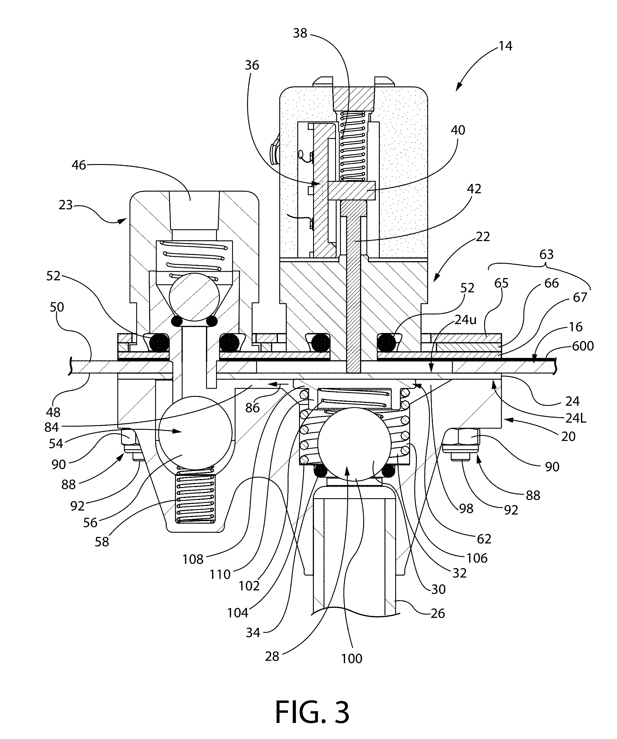
[0056] FIG. 3 is a front elevation in section of an injection molded diaphragm pump for liquid color with quick release in accordance with the invention, with the pump mounted on the lid of a liquid color container and the liquid color container lid shown fragmentally.
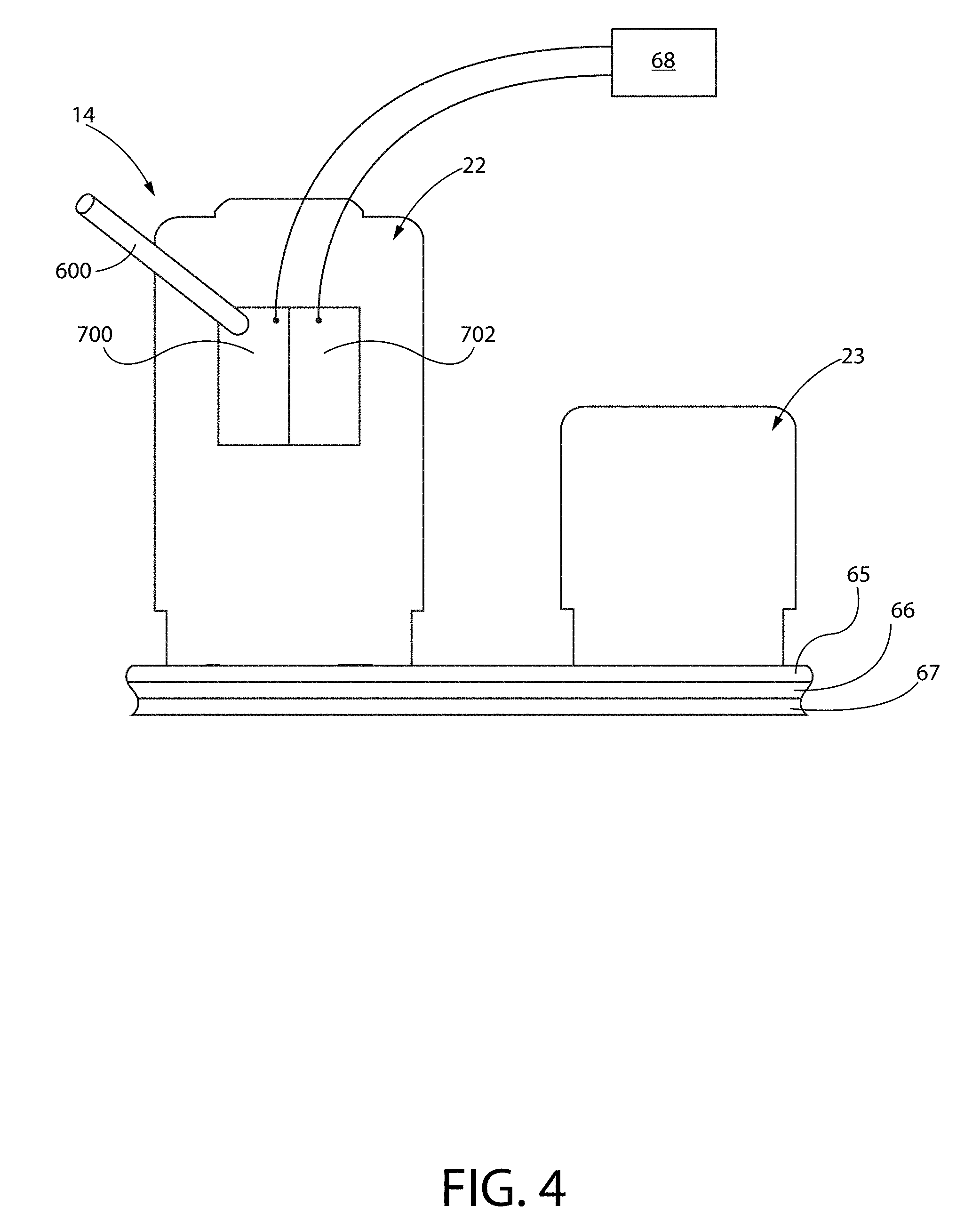
[0057] FIG. 4 is a schematic rear elevation of the injection molded diaphragm pump illustrated in FIG. 3.
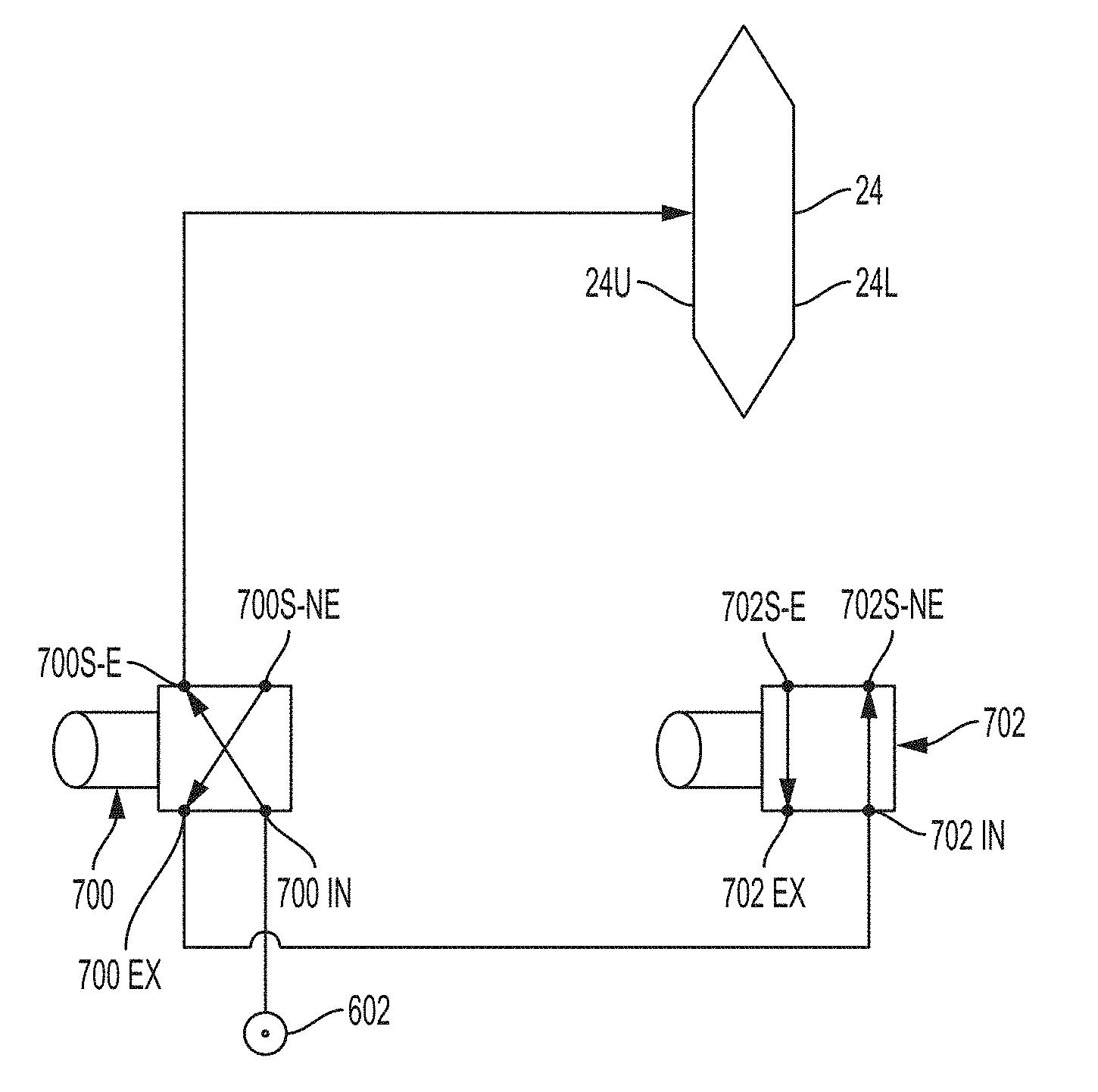
[0058] In FIGS. 1 and 2 schematically illustrating solenoid valves 700, 702, lines and arrows have been provided within the rectangular boxes schematically denoting solenoid valves 700, 702. These lines denote the positioning of the valve internals as respecting connection of the inlet port, the exhaust port, the valve energized supply port and the valve non-energized supply port, according to the state of energization of the valve. For example, in FIG. 1 valve 700 has diagonal arrow from inlet port 700IN leading to valve energized supply port 700S-E, and a second diagonal arrow leading from valve non-energized supply port 700S-NE to valve exhaust port 700EX. These diagonal arrows indicate that when solenoid valve 700 is energized, which is the condition illustrated in FIG. 1, inlet port 700IN is connected to valve energized supply port 700S-E and non-energized valve supply port 700S-NE is connected to valve exhaust port 700EX. Still referring to FIG. 1, the arrows for solenoid valve 702 indicate that in this state, when solenoid valve 702 is not energized, inlet port 702IN is connected to valve non-energized supply port 702S-NE, and valve energized supply port 702S-E is connected to exhaust port 702EX.
[0059] In FIG. 2, the arrows indicating connection or lack of connection between the various ports of solenoid valves 700, 702 are reversed from that illustrated in FIG. 1, since in FIG. 2 solenoid valve 702 is energized and solenoid valve 700 is not energized.
Description of the Preferred Embodiments and Best Mode Known for Practice of the Invention
[0060] Referring to the drawings, in the pump of the invention air (or another pumping fluid) under pressure is applied to an upper side 24U of a diaphragm 24, to press diaphragm 24 downwards. This downward movement of diaphragm 24 defines the "pumping stoke". In the pump, a spring 106 on bottom side 24L of the diaphragm acts to urge diaphragm 24 up. Upward movement of diaphragm 24 in response to the force of spring 106 defines the "suction stroke".
[0061] Moving the diaphragm downward through part of all of the full range of motion is preferably accomplished by operation of solenoid actuated air valves 700, 702 and applying air pressure, as described in more detail below, to move the diaphragm optionally all the way to the bottom of its range of motion, which may be to the bottom of the pumping cavity 98 or to move the diaphragm through less than its full range of motion.
[0062] Referring to FIGS. 1 and 2, solenoid valves 700, 702 provide pressurized air to diaphragm 24, specifically to the upper surface 24U of diaphragm 24, which is the upper side of diaphragm 24 illustrated in FIG. 3 and is the surface of diaphragm 24 that is contacted by pin 42 as pin 42 rides diaphragm 24 to provide positional data respecting the position of diaphragm 24 via signals generated by potentiometer 36 as slide bar 40 moves with pin 42.
[0063] Solenoid valves 700, 702 are mounted on the rear of liquid color pump inlet section 22 as illustrated in FIG. 4. Solenoid valves 700, 702 are controlled by microprocessor 68 and are connected thereto desirably by electric lines 603, 604. Of course, wireless connection is also feasible and desirable in connection with the practice of this invention.
[0064] Compressed air is supplied to first solenoid valve 700 by a house air line 602 as illustrated in FIG. 4.
[0065] When liquid color is used to color plastic parts during fabrication, careful metering of liquid color consumption is required as the liquid color is added while the plastic resin is melted and processed by a process machine. The rate the liquid color is dispensed by the pump must exactly match the rate at which the liquid color is consumed by the process machine. Hence, rate or speed of the liquid color pumping process must be precisely controlled. In some applications only require partial pump strokes are required. The rate at which liquid color is supplied by the pump is controlled by carefully pulsing only very small bursts of air into the pump, into the space above the diaphragm. Regulating the duration of each air pulse and regulating the time between pulses results in metering the liquid color to the process machine at exactly the desired flow rate so that the process machine receives precisely the amount of liquid color the process requires, at exactly the right rate of supply of liquid color.
[0066] Critical to the success of this process for supplying liquid color is having continuous feedback of the exact position of the diaphragm at all times as compressed air released by solenoid valve 700 pushes the diaphragm downward. Knowing the exact position of the diaphragm at all times allows accurate continuous monitoring and correction of the liquid color flow rate by regulation of the solenoid valves 700, 702 by the potentiometer 36 and microprocessor 68, and also allows accurate metering of partial stokes of diaphragm 24.
[0067] The invention accomplishes this by providing a pin 42 that lightly rides the upper surface 24U of diaphragm 24, following the diaphragm as the diaphragm moves down and up. The invention further involves positioning potentiometer 36, most desirably a linear slide potentiometer, so that potentiometer 36 is actuated by movement of pin 42.
[0068] In one preferred embodiment, total diaphragm movement may be about 0.25 inch. The potentiometer T-bar arm 40 and pin 42 may move about 0.75 inch or more, but in the preferred embodiment, the invention typically uses only 0.25 inch of that stroke.
[0069] Initially, microprocessor 68 preferably records the upper and lower extreme positions of the linear potentiometer slider arm 40, corresponding to the upper and lower limits of diaphragm travel. The microprocessor 68 then uses the readings of potentiometer 36 that are between the corresponding upper and lower limits of diaphragm travel to determine the exact location of diaphragm 24 as diaphragm 24 moves up and down and pumps liquid color. A 0.25 inch maximum travel stroke of diaphragm 24 translates into about 300 different position readings of the pin 42 and potentiometer 36, which may be stored and used by microprocessor 68, assuring precise readout of diaphragm location at any time.
[0070] Referring to FIG. 3, liquid color pump 14 is mounted on a lid 16 of a liquid color container and secured thereto by nut and bolt combinations 88, as illustrated in FIG. 3. Each nut and bolt combination 88 includes a nut 90 and a bolt 92, with the head of a bolt 92 being exterior of the liquid color drum lid 16 and a corresponding nut 90 being within the drum below drum lid 16.
[0071] Referring still to FIG. 3 and to FIG. 4, pump 14 includes a pump inlet section 22, a pump outlet section 23 defined generally by a quarter turn adaptor outlet fitting, and a molded one piece lower body portion 20.
[0072] As illustrated in FIG. 3, bolts 92 pass through a collection 63 of sandwiched plates 65, 66, 67 that provide a quick release for both pump inlet section 22 and pump outlet section 23, with bolts 92 further passing through an aperture in drum lid 16 and suitable holes formed in molded one piece lower body portion 20 of pump 14. These holes are formed in bosses resulting as one piece lower body portion 20 is molded.
[0073] One piece lower body portion 20 is a single molded piece of plastic of integral construction. There is no assembly or fabrication activity involved as respecting finishing one piece lower body portion 20 and making it ready for incorporation into pump 14 once one piece lower body portion 20 is ejected from the mold of an injection molding machine. The only finishing that may occasionally be necessary is removal of any flash resulting from the molding process.
[0074] A liquid color inlet conduit 26 extends downwardly from molded one piece lower body portion 20 and communicates with pumping chamber 98 of molded one piece lower body portion 20 via a liquid color inlet aperture 100 formed in molded one piece lower body portion 20. A liquid color inlet check valve, located at liquid color inlet aperture 100 to molded lower body portion 20, is designated generally 28 in FIG. 3 and includes a liquid color inlet check valve ball 30, which is biased against a liquid color inlet check valve seat 34, which seat is preferably defined by an O-ring. Closure bias for liquid color inlet check valve ball 30 is provided by liquid color inlet check valve bias spring 102.
[0075] Liquid color inlet check valve ball 30 resides within and is movable freely with respect to a diaphragm return spring designated 32 in FIG. 3. Diaphragm return spring 32 is positioned to rest on a shoulder 104 of a cylindrically shaped portion 106 formed in the open interior of one piece lower body portion 20. Diaphragm return spring 32 is constrained at its upper end by contact with the underside of a diaphragm support cup 62. An upper surface of diaphragm support cup 62 facingly contacts the lower surface 24L of diaphragm 24. Diaphragm support cup 62 includes a horizontal planar portion 108 and an annular portion 110 extending downwardly from portion 108. Annular portion 110 separates diaphragm return spring 32 from inlet check valve bias spring 102, as illustrated in FIG. 3.
[0076] As illustrated in FIG. 3, the injection molded diaphragm pump with liquid color for quick release further includes slide potentiometer 36, with the potentiometer having a T-bar 40 for detecting the position of diaphragm position sensing pin 42. An optional spring 38 provides slight bias via T-bar 40 to assure position sensing pin 42 remains in light, riding contact with diaphragm 24. Gravity may be relied on in lieu of spring 38.
[0077] A pumped color liquid outlet from pump outlet section 23 is designated 46. The bottom interior surface of liquid container lid 16 is designated 48 and the top exterior surface of liquid container lid 16 is designated 50. O-rings 52 are provided to seal the quick disconnect inlet section 22 and the quick disconnect liquid color outlet assembly 23 relative to an uppermost plate 65 of quick disconnect sandwich 63 consisting of plates 65, 66, 67, which are bolted to drum lid 16 by nut-bolt combinations 88 as described.
[0078] The pump assembly further includes a liquid color outlet shutoff valve designated generally 54, a liquid color outlet shutoff valve ball designated 56, and a liquid color outlet shutoff valve spring designated 58. The sandwich-like quick disconnect plate assembly provided as 63 includes quick disconnect retainer plate 65, quick disconnect spacer plate 66, and quick disconnect base plate 67. An optional gasket 600 may be interposed between upper surface 50 of drum lid 16 and a lower, unnumbered surface of quick disconnect base plate 67, which faces drum lid 16.
[0079] Microprocessor 68 actuates and operates solenoid valves 700, 702, which supply air as needed to the upper side of diaphragm 24 from a house air line 602, as illustrated in FIG. 4. A voltage potential outlet signal line 76 from potentiometer 36 works in conjunction with microprocessor 68 to effectuate effective control of valves 700, 702.
[0080] A recess 84 formed in the upper surface of pump molded one-piece lower body portion 20 defines a channel designated by arrow 86, which shows the direction of flow of liquid color from a pumping section of the pump, defined generally by the structure underlying quick disconnect inlet section 22, to an outlet section of the pump defined generally quarter turn quick disconnect liquid color outlet assembly 23.
[0081] When pump outlet section 23, defined generally by the quarter turn adapter outlet fitting, is not present (as having been removed by rotating it a quarter turn so that the unnumbered feet of that fitting do not engage channels in spacer plate 66), ball 56 of liquid color shut off valve 54 pops up due to the force applied to it by liquid color shut off valve spring 58, which is immediately below ball 56 and in contact therewith. As ball 56 rises, ball 56 encounters a hole in plate 16, or optionally a hole in gasket 24 underlying plate 16 (if gasket 24 is configured to extend that far to the left in FIG. 3), and ball 56 seals the hole due to the spring force exerted by liquid color shut off valve spring 58 on ball 56. Hence with ball 56 sealing the hole no liquid color can escape from the pump and the pump has been "shut off."
[0082] When pump outlet section 23 is put into position with a quarter turn so that the unnumbered feet thereof engage the unnumbered channels defined by retainer plate 65 and spacer plate 66 and are retained in place thereby, the unnumbered lower extremity of a downwardly extending annular channel in pump outlet section 23 contacts ball 56 and pushes ball 56 down against the force of liquid color shut off valve spring 58, thereby allowing liquid color pumped by action of diaphragm 24 to flow to the left in FIG. 3 and from there to flow upwardly through the channel and associated passageway in pump outlet section 23, and out of the pump through the pump liquid color outlet 46.
[0083] Referring to the schematic drawings presented as FIGS. 1 and 2 showing the operation of first and second solenoid valves 700, 702, each of the first and second solenoid valves 700, 702 have an inlet port, an exhaust port, a valve energized supply port, and a valve non-energized supply port. The inlet port, exhaust port, valve energized supply port, and valve non-energized supply port are respectively indicated by "IN" for "inlet port", "EX" for "exhaust port", "S-E" for "valve energized supply port" and "S-NE" for "valve non-energized supply port." Each of first and second solenoid valves 700, 702 have their respective inlet ports, exhaust ports, valve energized supply ports and valve non-energized supply ports indicated by the corresponding appropriate alphabetic combinations in FIGS. 1 and 2.
[0084] As shown in FIG. 1, when compressed air (or some other pumping fluid) in pulses is to be provided to the upper side of diaphragm 24, with upper side of diaphragm 24 denoted 24U, air from the house air line 602 is supplied to inlet port 700IN of first solenoid valve 700. Upon energization of first solenoid valve 700, inlet port 700IN is connected to valve energized supply port 700S-E, which connects to the unnumbered open interior of pump inlet section 22 and a compressed air pulse is resultingly applied to upper side 24U of diaphragm 24.
[0085] As soon as the required pulse has been applied for the required duration, as controlled by microprocessor 68 monitoring displacement of diaphragm 24 as sensed by slide potentiometer 36, valve 700 is de-energized. However, upon de-energization of valve 700 the compressed air applied to the diaphragm upper surface 24U remains present and cannot escape, since the inlet port 7001N of first solenoid valve 700 is connected to exhaust port 700EX, and exhaust port 700EX is in turn connected to the inlet port 7021N of solenoid valve 702. Since solenoid valve 702 is not energized, air entering inlet port 7021N of solenoid valve 702 attempts to go to valve non-energized supply port 702S-NE.
[0086] However, in the implementation of the invention illustrated in FIGS. 1 and 2, the non-energized supply port 702S-NE of valve 702 is permanently blocked. Hence, as first solenoid valve 700 is cycled on and off, with each "on" cycle of first solenoid valve 700, air pressure builds against the upper side 24U of diaphragm 24, thereby further displacing diaphragm 24 downwardly in FIG. 3 and effectively pumping liquid color present in pumping chamber 98 in FIG. 3 out of that chamber, with the liquid color moving to the left in FIG. 3 through channel 84 as indicated by arrow 86 and upwardly through pump outlet section 23 defined generally by a quarter turn adapter outlet fitting, as illustrated.
[0087] As first solenoid valve 700 continues to cycle on and off and continues thereby to force additional air pressure against upper side 24U of diaphragm 24, diaphragm 24 continues to deflect downwardly considering FIG. 3, thereby forcing additional liquid color out of pumping chamber 98 through channel 84 and out of pump 14 as explained above.
[0088] Once the slide potentiometer 36 indicates that the diaphragm 24 has reached its maximum displacement and has pumped the maximum, or a desired, amount of liquid color at a desired rate, first solenoid valve 700 is de-energized and second solenoid valve 702 is energized. This opens a passageway for escape of the air that had been pressing against upper surface 24U of diaphragm 24 with that air flowing out of de-energized first solenoid valve 700 by passing through port 700S-E and then port 700EX and on to now energized second solenoid valve 702 entering valve 702 through inlet port 7021N and then venting to atmosphere through solenoid valve 702 by exiting that valve via energized supply port 702S-E.
[0089] While operation and the structure of the invention as disclosed has shown first and second solenoid valves 700, 702 as four-port valves, three-port valves could equally well be used, whereupon energization of such a three-port valve, the inlet port is connected to a single supply port, and upon de-energization of the valve, the single supply port is connected to the valve exhaust port.
[0090] Three-port and four-port solenoid valves suitable for use in practice of the invention are available from MAC Valves located at 30569 Beck Road, Wixom, Mich.
[0091] Use of the four-port solenoid valve in the preferred embodiment of the invention facilitates the delivery of air in extremely small amounts to provide fine, very precise control of movement of diaphragm 24. First solenoid valve 700 is turned on and off for very short "on" times, such as ten milliseconds, namely 1/100.sup.th of a second. This provides a very short pulse of air against the upper side of the diaphragm 24. When first solenoid valve 700 is turned off, the air just delivered against the upper side 24U of diaphragm 24 would normally escape by flowing back through the solenoid valve and exiting exhaust port 700EX. However, this is not the way the invention in its preferable mode works, as the invention does not want this air to be exhausted until diaphragm 24 has completed its full pumping displacement as controlled by the microprocessor for the particular liquid color being supplied and the particular process machine being serviced thereby. Accordingly, a second solenoid valve, solenoid valve 702, is connected to the exhaust port of first solenoid valve 700 and is used to keep exhaust port 700EX closed until venting is required.
[0092] When it is time to relieve the pressure on diaphragm 24 to allow diaphragm 24 to return to its neutral position and to allow liquid color to flow upwardly into pumping chamber 98 that has been pumped free of liquid color, air must be exhausted from the upper side 24U of the diaphragm, so second solenoid valve 702 is energized and the air is vented to atmosphere as indicted by arrow 606 in FIG. 2. Presence of second solenoid valve 702 maintaining air pressure in the system as air pressure is incrementally applied to the diaphragm surface 24U by the on and off action of first solenoid valve 700 facilitates the ultrafine control of the feeding of liquid color that is effectuated by the instant invention.
[0093] Note that in the four port solenoid valve implementation of the invention ports 700S-NE and 702S-NE preferably are permanently sealed.
[0094] Although schematic implementations of present invention and at least some of its advantages are described in detail hereinabove, it should be understood that various changes, substitutions and alterations may be made to the apparatus and methods disclosed herein without departing from the spirit and scope of the invention as defined by the appended claims. Moreover, the scope of this patent application is not intended to be limited to the particular implementations of apparatus and methods described in the specification, nor to any methods that may be described or inferentially understood by those skilled in the art to be present as described in this specification.
[0095] As one of skill in the art will readily appreciate from the disclosure of the invention as set forth hereinabove, apparatus, methods, and steps presently existing or later developed, which perform substantially the same function or achieve substantially the same result as the corresponding embodiments described and disclosed hereinabove, may be utilized according to the description of the invention and the claims appended hereto. Accordingly, the appended claims are intended to include within their scope such apparatus, methods, and processes that provide the same result or which are, as a matter of law, embraced by the doctrine of the equivalents respecting the claims of this application.
[0096] As respecting the claims appended hereto, the term "comprising" means "including but not limited to", whereas the term "consisting of" means "having only and no more", and the term "consisting essentially of" means "having only and no more except for minor additions which would be known to one of skill in the art as possibly needed for operation of the invention."
* * * * *
D00000
D00001
D00002
D00003
D00004
XML
uspto.report is an independent third-party trademark research tool that is not affiliated, endorsed, or sponsored by the United States Patent and Trademark Office (USPTO) or any other governmental organization. The information provided by uspto.report is based on publicly available data at the time of writing and is intended for informational purposes only.
While we strive to provide accurate and up-to-date information, we do not guarantee the accuracy, completeness, reliability, or suitability of the information displayed on this site. The use of this site is at your own risk. Any reliance you place on such information is therefore strictly at your own risk.
All official trademark data, including owner information, should be verified by visiting the official USPTO website at www.uspto.gov. This site is not intended to replace professional legal advice and should not be used as a substitute for consulting with a legal professional who is knowledgeable about trademark law.