Treatment Of Produced Water With Seeded Evaporator
XIA; Jiyang
U.S. patent application number 14/428138 was filed with the patent office on 2019-01-24 for treatment of produced water with seeded evaporator. The applicant listed for this patent is BL TECHNOLOGIES, INC.. Invention is credited to Jiyang XIA.
| Application Number | 20190024492 14/428138 |
| Document ID | / |
| Family ID | 50263141 |
| Filed Date | 2019-01-24 |

| United States Patent Application | 20190024492 |
| Kind Code | A9 |
| XIA; Jiyang | January 24, 2019 |
TREATMENT OF PRODUCED WATER WITH SEEDED EVAPORATOR
Abstract
Produced water, for example from a steam assisted gravity drainage (SAGD) or cyclic steam stimulation (CSS) heavy oil recovery operation, is treated to recover water that is re-used to create steam. The produced water is treated in one or more thermal treatment devices such as an evaporator and a crystallizer. The thermal treatment device is seeded, for example with a calcium or magnesium salt. The thermal treatment device produces a blowdown or slurry comprising super-saturated solids and organic compounds. A solvent is added to the blowdown or slurry. The solids precipitate and are separated from the blowdown or slurry. The solvent may be recovered for re-use in treating more blowdown or slurry.
| Inventors: | XIA; Jiyang; (Shnaghai, CN) | ||||||||||
| Applicant: |
|
||||||||||
|---|---|---|---|---|---|---|---|---|---|---|---|
| Prior Publication: |
|
||||||||||
| Family ID: | 50263141 | ||||||||||
| Appl. No.: | 14/428138 | ||||||||||
| Filed: | August 19, 2013 | ||||||||||
| PCT Filed: | August 19, 2013 | ||||||||||
| PCT NO: | PCT/US2013/055544 PCKC 00 | ||||||||||
| 371 Date: | March 13, 2015 |
Related U.S. Patent Documents
| Application Number | Filing Date | Patent Number | ||
|---|---|---|---|---|
| 61700645 | Sep 13, 2012 | |||
| Current U.S. Class: | 1/1 |
| Current CPC Class: | C02F 9/00 20130101; C02F 2101/32 20130101; C02F 1/048 20130101; E21B 43/40 20130101; C02F 1/52 20130101; C02F 1/40 20130101; C02F 1/26 20130101; E21B 43/24 20130101; E21B 43/2408 20130101; C02F 2001/5218 20130101; C02F 2103/10 20130101; C02F 1/72 20130101 |
| International Class: | E21B 43/40 20060101 E21B043/40; C02F 9/00 20060101 C02F009/00; E21B 43/24 20060101 E21B043/24 |
Foreign Application Data
| Date | Code | Application Number |
|---|---|---|
| Oct 31, 2012 | CA | 2794356 |
Claims
1. A process for extracting oil, the process comprising the steps of: a) producing steam; b) injecting the steam into a formation comprising oil; c) withdrawing a mixture of water and oil from the formation; d) separating produced water from the mixture of water and oil; e) treating the produced water including in a seeded evaporator to produce a distillate and a blowdown; f) using the distillate to produce additional steam for injection into the formation; g) mixing a solvent with the blowdown; and, h) after step g), separating precipitated solids comprising the one or more salts from the slurry.
2. The process of claim 1, wherein the oil is heavy oil or bitumen.
3. The process of claim 1, wherein steps a), b), and c) are part of a steam assisted gravity drainage (SAGD) or cyclic steam stimulation (CSS) operation.
4. The process of claim 1, wherein step e) comprises treating the produced water with an evaporator to produce an evaporator blowdown and treating the evaporator blowdown in a crystallizer to produce the blowdown.
5. The process of claim 1, wherein the solvent comprises DIPA.
6. The process of claim 1, wherein the precipitated solids comprise silica.
7. The process of claim 1, further comprising steps of recovering solvent from the mixture with the blowdown and mixing recovered solvent with additional blowdown.
8. The process of claim 7, further comprising a step of removing a remainder of the blowdown from the process after the steps of recovering solvent and separating precipitated solids.
9. The process of claim 7, further comprising treating organic compounds in a remainder of the blowdown and returning treated blowdown to the process at or upstream of step e).
10. A method for treating a mixture having water, one or more salts in solution and one or more organic compounds, the method comprising the steps of, a) treating the mixture in an evaporator to produce a concentrate; b) adding a source of ions to concentrate in the evaporator; b) mixing concentrate with a solvent; and, c) removing precipitates of the one or more salts and one or more organic compounds from the seeded concentrate.
11. The method of claim 10, further comprising a step of recovering at least some of the solvent from the mixture of concentrate and solvent.
12. The method of claim 11, further comprising a step of mixing recovered solvent with additional concentrate.
13. The method of claim 10, wherein the water comprises produced water.
14. The method of claim 13, wherein the produced water is extracted from a heavy oil containing formation after injecting steam into the formation.
15. The method of claim 10, wherein the concentrate comprises blowdown from one or more thermal treatment devices.
16. The method of claim 15, wherein the thermal treatment devices comprise an evaporator or an evaporator and a crystallizer.
17. The method of claim 10, further comprising a step of treating at least some of the seeded concentrate after step d) to oxidize or remove organic compounds and returning the treated seeded concentrate to step a).
18. The method of claim 10, wherein the concentrate has a WSO of 3 wt % or more and the WSO is 20% or more of the TS of the concentrate.
19. An apparatus for treating produced water, the apparatus comprising: a) a seeded evaporator to treat the produced water and produce a blowdown stream; b) a solvent mixing vessel, the solvent mixing vessel in communication with the blowdown stream; c) a solvent feeding system in communication with the solvent mixing vessel; and, d) a solid-liquid separation device.
20. The apparatus of claim 19, wherein the solid-liquid separation device is incorporated with, or downstream of, the solvent mixing vessel.
21. The apparatus of claim 19, wherein the one or more thermal treatment devices comprise two or more thermal treatment devices in series.
22. The apparatus of clam 21, wherein the one or more thermal treatment devices comprise an evaporator and a crystallizer.
23. The apparatus of claim 19, further comprising a solvent recovery system downstream of the solvent mixing vessel.
24. The apparatus of claim 23, further comprising a treatment system configured to oxidize or remove organic compounds downstream of the solvent recovery system.
25. A process for treating produced water from heavy oil extraction, the process comprising the steps of: a) de-oiling the produced water; b) treating the de-oiled produced water in a seeded evaporator to produce an evaporator blowdown; c) adding a solvent to the blowdown; and, d) separating solids from the blowdown.
26. The process of claim 25, further comprising, after step d), a step of recovering solvent from the blowdown.
27. The process of claim 26, further comprising a step of treating the blowdown to remove or oxidize one or more organic compounds in the blowdown and returning treated blowdown to, or upstream of, step b).
Description
FIELD OF THE INVENTION
[0001] This specification relates to a method and apparatus for treating water, for example produced water.
BACKGROUND
[0002] Canadian Patent 2 509 309 by Heins, entitled Water Treatment Method for Heavy Oil Production Using Calcium Sulfate Seed Slurry Evaporation, describes an evaporator based method of treating produced water from heavy oil production. Produced water is first treated in a de-oiling step to reduce oil and grease to about 20 parts per million or less. De-oiled water is introduced into an evaporator to produce a distillate and an evaporator blowdown containing concentrated residual solids. The distillate is used, optionally after further polishing, to create steam in a once-through steam generator or other boiler. The evaporator blowdown may be further treated in a crystallizer.
SUMMARY
[0003] The following summary is intended to introduce the reader to the detailed description to follow and not to limit or define the claimed invention.
[0004] Evaporator blowdown may require treatment to remove silica and/or other contaminants before it can be disposed or re-used. A crystallizer, for example, ordinarily treats evaporator blowdown to recover water and produce dry, or easily dried, crystals made up of solids precipitated from the blowdown. However, when a crystallizer is used to treat produced water, particularly produced water from heavy oil production, the crystallizer may instead produce a slurry. The slurry contains salts, for example silica salts, at concentrations above their ordinary limits of solubility in water and yet the solids are not crystallized and cannot be easily separated from the slurry. Concentrated organic compounds from the produced water remaining in the slurry may interfere with crystal growth and precipitation even for over saturated salts in the slurry.
[0005] In a method and apparatus described in this specification, a source of ions, for example magnesium or calcium ions, is added to the evaporator. A solvent, for example diisopropylamine (DIPA), isopropylamine (IPA), methanol or alcohol, is added to the blowdown. The solvent is later recovered from the solvent-blowdown mixture. Solids are separated from the blowdown before or after the solvent is recovered. Optionally, the blowdown may be further concentrated, for example in a crystallizer, before the solvent is added. Optionally, treated blowdown may be returned to the evaporator.
[0006] The method and apparatus are useful, for example, in providing an alternative means of treating produced water, or other water containing dissolved salts and organic compounds. The method and apparatus may be incorporated into a method and apparatus for extracting heavy oil.
BRIEF DESCRIPTION OF THE FIGURE
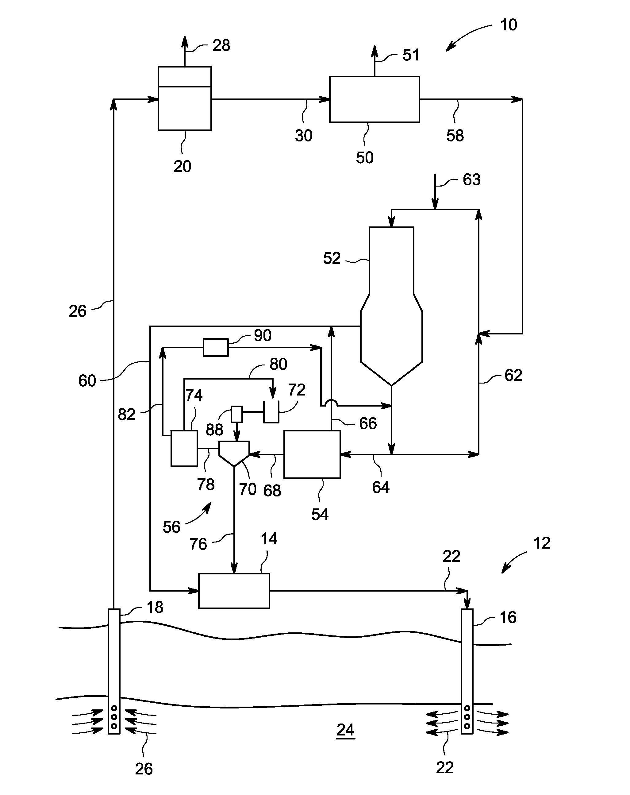
[0007] FIG. 1 is a schematic process flow diagram of a produced water treatment system combined with a heavy oil extraction system.
DETAILED DESCRIPTION
[0008] FIG. 1 shows a water treatment system 10 in combination with a heavy oil, for example bitumen, recovery system 12. The heavy oil recovery system 12 has a boiler 14, an injection well 16, a production well 18 and an oil-water separator 20. The boiler 14 may be, for example, a once through steam generator (OTSG) or a packaged boiler. The boiler 14 produces steam 22 which flows to the injection well 16. Injection well 16 carries the steam 22 into a geologic formation 24 containing heavy oil, for example bitumen in the oil sands areas of Alberta, Canada. The steam 22 fluidizes bitumen in the formation 24 and later condenses. An oil and water mixture 26 is produced and withdrawn from the production well 18. The oil and water mixture 26 is sent to the oil-water separator 20. Product oil 28 is removed from the oil-water separator 20 for further refining. Produced water 30, which remains after the product oil 28 is removed from the oil and water mixture 26, flows to the water treatment system 10 for further treatment. The heavy oil recovery system 12 may be, for example, a steam assisted gravity drainage (SAGD) or cyclic steam stimulation (CSS) system.
[0009] The water treatment system 10 has a de-oiling unit 50, an evaporator 52, optionally a crystallizer 54, and a blowdown treatment system 56. The de-oiling unit 50 receives the produced water 30 and removes additional oil 51, for example emulsified oil, from the produced water 30 to produce de-oiled water 58. The de-oiling unit 50 may be, for example, a dissolved gas flotation unit, a walnut shell filtration unit, a de-oiling polymer mixing tank, a sorbent unit, a membrane filtration unit or another device. A suitable evaporator 52 and crystallizer 54 are available from GE Ionics, Inc.
[0010] De-oiled water 58 is treated further in the evaporator 52. Optionally, the de-oiled water 58 may pass through intermediate treatment steps on the way to evaporator 52. However, a warm lime softener is not required and is not provided in an embodiment.
[0011] Evaporator 52 may be, for example, a mechanical vapour recompression (MVC or MVR) evaporator. The evaporator 52 may use a falling film or other internal arrangement. The evaporator 52 may have associated equipment used, for example, to alter the pH of the de-oiled water or remove gasses or alkalinity from the de-oiled water 58. The evaporator 52 removes water vapour from the de-oiled water 58. The removed water vapour, when condensed, forms distillate 60 which is returned to the boiler 14 for re-use in the heavy oil recovery system 12, optionally after further treatment.
[0012] The evaporator 52 also has a brine recirculation loop 62. A seeding chemical 63 is added to the evaporator 52, for example by injection into the brine recirculation loop 62 as shown, the sump of the evaporator, a feed line to the evaporator or by other means. The seeding chemical 63 may be, for example, a magnesium oxide or calcium salt. The seeding chemical may be added in a dry form or in solution. A suitable magnesium salt is magnesium oxide. A suitable calcium salt is calcium sulfate (gypsum).
[0013] An evaporator blowdown 64 is withdrawn from the brine recirculation loop 62 and fed to the blowdown treatment system 56. Optionally, the blowdown treatment system 56 may be located within the brine recirculation loop 62. The evaporator blowdown 64, and the water in the brine circulation loop 62, have a high concentration of various contaminants that were present in the de-oiled water 58. In particular, the evaporator blowdown 64 and water in the brine circulation loop 62 have a high concentration of silica. The evaporator blowdown 64 is therefore not suitable for discharge in many locations. The use of a seeding chemical and a solvent (to be described below) may be particularly useful when the evaporator blowdown 64 or liquid in the brine recirculation loop 62 has a water soluble organics concentration (WSO) of 3 wt % or more and the WSO concentration is 20% or more of the total solids (TS) concentration. TS is measured by heating a sample to 105 degrees C. to remove water, then dividing the dry sample mass by the original sample mass. Total dissolved solids (TDS) is is measured by heating a sample to 550 degrees C. to remove water and organics, then dividing the dry sample mass by the original sample mass. WSO is calculated as the difference between TS and TDS.
[0014] In the water treatment system 10, the evaporator blowdown 64 may be treated further in the optional crystallizer 54. Crystallizer 54 removes additional water vapour from the evaporator blowdown 64 which, when condensed, forms second distillate 66. Second distillate 66 may be returned to the boiler 14 for re-use in the heavy oil recovery system 12, optionally after further treatment.
[0015] The crystallizer 54 also produces a crystallizer blowdown 68. Crystallizer blowdown 68 has an even higher concentration of silica and other dissolved solids compared to the evaporator blowdown 64. Under some conditions, particularly when treating produced water 30 from a steam or water flood assisted oil recovery operation, the crystallizer 54 produces a crystallizer blowdown 68 in the form of a slurry having a high solids concentration. Silica and other dissolved solids are present in the slurry under super-saturated conditions but do not precipitate and settle from the slurry. For example, the crystallizer blowdown 68 may have a total solids (TS) content of 25 wt % or more or 50 wt % or more.
[0016] The evaporator 52 and crystallizer 54 are types of thermal treatment devices, alternatively called distillation devices. Optionally, alternative thermal treatment devices or concentrating devices, in one or more stages, may be used to create slurry similar to the crystallizer blowdown 68 or mixtures similar to evaporator blowdown 64 or water in the brine recirculation loop 62. Total organic carbon (TOC) in any of these mixtures 62, 64, 68 may be 2 wt % of more; total dissolved solids (TDS) may be 10 wt % or more; and, silica may be 1.5 wt % or more. Blowdown treatment system 56 may be located to receive crystallizer blowdown 68 as shown, to receive evaporator blowdown 64 without there being a crystallizer 54, or to be part of brine recirculation loop 62 in which case evaporator blowdown 64 stream may be omitted, or retained as a smaller system bleed with or without evaporator 54.
[0017] The blowdown treatment system 56 shown comprises a reaction vessel 70, a solvent dosing system 72 and a solvent recovery system 74. The crystallizer blowdown 68 (or evaporator blowdown 64 or recirculating brine 62) and solvent from the solvent dosing system 72 are added to the reaction vessel 70 and mixed together. The reaction vessel 70 may be, for example, a mixing tank or a conduit with in-line mixing. The solvent may pass through a heat exchanger 88 to solvent and thereby cool the crystallizer blowdown 68 (or evaporator blowdown 64 or recirculating brine 62) before it enters the reaction vessel 70 if required to maintain a temperature in the reaction vessel 70 below the boiling point of the solvent or to maintain a temperature at which the solvent and water are miscible. Precipitated solids 76 form, settle and are removed from the bottom of the reaction vessel 70, which acts as an integrated solid-liquid separation unit. Alternatively, the precipitated solids 76 may be removed by a separate solid-liquid separation unit such as a centrifuge, filter press, hydrocyclone, filter or clarifier. In a further alternative, solvent may be recovered from the crystallizer blowdown 68 (or evaporator blowdown 64 or recirculating brine 62) before or after the precipitated solids 76 are removed.
[0018] The solvent is added in a mass ratio of at least 1:1, or about 5:1 or more, solvent to crystallizer blowdown 68 (or evaporator blowdown 64 or recirculating brine 62).
[0019] The remaining blowdown-solvent mixture 78 is sent to the solvent recovery system 74. The solvent recovery system 74 may comprise a heated decanting vessel. In the case of DIPA, heating the blowdown-solvent mixture 78 to about 74 degrees C. causes the solvent to separate from the water and form a liquid solvent phase over the water. The solvent is decanted and drawn off from the top of the solvent recovery system 74. Alternatively, other solvents such as IPA, methanol or ethanol can be extracted from the blowdown-solvent mixture 78 by distillation. Other solvent extraction means may be appropriate for other solvents. Recovered solvent 80 is sent to the solvent dosing system 72 for re-use in the blowdown treatment system 56.
[0020] The precipitated solids 76 may include some organic compounds. The precipitated solids 76 may be treated to remove the organic compounds if required to meet discharge or disposal requirements relating to the precipitated solids. For example, the precipitated solids 76 may be dried, heated, exposed to UV radiation, exposed to microorganisms, embodied in cement, or washed with water, the solvent used in the solvent recovery system 74, or another solvent.
[0021] A waste brine 82 is also produced. In a case where the blowdown treatment system 56 is located within the brine recirculation loop 62, the waste brine 82 flows to the evaporator 52 to complete the brine recirculation loop 62. In other options, the waste brine 82 may be discharged or recycled to the water treatment system 10, for example by being sent back to the evaporator 52. Treatment unit 90 may extract remaining solvent or remove organic contaminants form the waste brine 82. Optionally, chemicals may be added to the waste brine 82 to oxidize remaining organic compounds. Alternatively, or additionally, the organic compounds may be digested biologically. In a further alternative, the organic compounds may be recovered for their value as industrial chemicals. The treated waste brine 82 may be returned to the water treatment system 10. However, in some cases the waste brine 82 is removed from the water treatment system 10, optionally after treating the waste brine 82 if required to meet any standards required for discharge or disposal. In this way, the waste brine 82 provides a bleed of water soluble organic compounds from the water treatment system 10 to inhibit the accumulation of any organic compounds that are not effectively removed by any process in the water treatment system 10.
[0022] This written description uses examples to disclose the invention and also to enable any person skilled in the art to practice the invention. The patentable scope of the invention is defined by the claims, and may include other examples that occur to those skilled in the art.
* * * * *
D00000
D00001
XML
uspto.report is an independent third-party trademark research tool that is not affiliated, endorsed, or sponsored by the United States Patent and Trademark Office (USPTO) or any other governmental organization. The information provided by uspto.report is based on publicly available data at the time of writing and is intended for informational purposes only.
While we strive to provide accurate and up-to-date information, we do not guarantee the accuracy, completeness, reliability, or suitability of the information displayed on this site. The use of this site is at your own risk. Any reliance you place on such information is therefore strictly at your own risk.
All official trademark data, including owner information, should be verified by visiting the official USPTO website at www.uspto.gov. This site is not intended to replace professional legal advice and should not be used as a substitute for consulting with a legal professional who is knowledgeable about trademark law.