Open Water Coiled Tubing Sealing Device
Crawford; Neil ; et al.
U.S. patent application number 16/038453 was filed with the patent office on 2019-01-24 for open water coiled tubing sealing device. This patent application is currently assigned to Oceaneering International, Inc.. The applicant listed for this patent is Oceaneering International, Inc.. Invention is credited to Sam Almerico, John R. Cook, Neil Crawford, Caleb Fulks.
| Application Number | 20190024471 16/038453 |
| Document ID | / |
| Family ID | 65015328 |
| Filed Date | 2019-01-24 |


| United States Patent Application | 20190024471 |
| Kind Code | A1 |
| Crawford; Neil ; et al. | January 24, 2019 |
Open Water Coiled Tubing Sealing Device
Abstract
Dynamic/static sealing of coiled tubing subsea for pipeline and well access with hydrostatic conditions up to 10,000 feet water depth while maintaining wellbore or pipeline pressures up to 10,000 psi may be achieved using a system comprising a subsea fluid source which utilizes a riserless open water coiled tubing system and an open water coiled tubing sealer to control hydrostatic pressure and wellbore/pipeline pressures. This comprises an upper well control assembly having a first geometric orientation and a lower well control assembly in fluid communication with the upper well control assembly aligned in a second geometric orientation substantially inverted to the first orientation; a quick disconnect connector in fluid communication with the upper well control assembly; one or more electrically powered subsea assist jacks operatively connected to the quick disconnect connector; a controller operatively in communication with the electrically powered subsea assist jacks; and a power connector operatively in communication with the source of electrical power, the controller, and the electrically powered subsea assist jack.
| Inventors: | Crawford; Neil; (The Woodlands, TX) ; Almerico; Sam; (The Woodlands, TX) ; Cook; John R.; (Kingwood, TX) ; Fulks; Caleb; (McKinney, TX) | ||||||||||
| Applicant: |
|
||||||||||
|---|---|---|---|---|---|---|---|---|---|---|---|
| Assignee: | Oceaneering International,
Inc. Houston TX |
||||||||||
| Family ID: | 65015328 | ||||||||||
| Appl. No.: | 16/038453 | ||||||||||
| Filed: | July 18, 2018 |
Related U.S. Patent Documents
| Application Number | Filing Date | Patent Number | ||
|---|---|---|---|---|
| 62534333 | Jul 19, 2017 | |||
| Current U.S. Class: | 1/1 |
| Current CPC Class: | E21B 33/0355 20130101; E21B 43/013 20130101; E21B 19/22 20130101; E21B 33/038 20130101; E21B 33/076 20130101 |
| International Class: | E21B 33/035 20060101 E21B033/035; E21B 33/038 20060101 E21B033/038; E21B 33/076 20060101 E21B033/076 |
Claims
1. An open water coiled tubing sealer to control hydrostatic pressure and wellbore/pipeline pressures, comprising: a. an upper well control assembly having a first geometric orientation; b. a lower well control assembly in fluid communication with the upper well control assembly, the lower well control assembly comprising a second geometric orientation substantially inverted to the first orientation; c. a quick disconnect connector in fluid communication with the upper well control assembly; d. an electrically powered subsea assist jack operatively connected to the quick disconnect connector, the electrically powered subsea assist jack comprising: i. an electric motor; ii. a power connector operatively in communication with the electric motor; and iii. a power convertor operatively in communication with the electric motor; e. a controller operatively in communication with the electrically powered subsea assist jack; and f. a power connector operatively in communication with the source of electrical power, the controller, and the electrically powered subsea assist jack.
2. The open water coiled tubing sealer to control hydrostatic pressure and wellbore/pipeline pressures of claim 1, wherein the controller further comprises: a. a feedback loop adapted to provide data communication over the power connector; b. an electronic sensor; and c. a position sensor operatively in communication with the electrically powered subsea assist jack and operative to provide feedback on a position of an internal element of the electrically powered subsea assist jack.
3. The open water coiled tubing sealer to control hydrostatic pressure and wellbore/pipeline pressures of claim 1, wherein the source of electrical power comprises a skid based source of electrical power.
4. The open water coiled tubing sealer to control hydrostatic pressure and wellbore/pipeline pressures of claim 1, further comprising a coiled tubing packer disposed intermediate the electrically powered subsea assist jack and the quick disconnect connector.
5. The open water coiled tubing sealer to control hydrostatic pressure and wellbore/pipeline pressures of claim 1, wherein the upper well control assembly comprises a plurality of control assemblies.
6. The open water coiled tubing sealer to control hydrostatic pressure and wellbore/pipeline pressures of claim 1, wherein: a. the upper well control assembly comprises a plurality of control assist assemblies arranged into pairs; and b. the lower well control assembly comprises a plurality of control assist assemblies arranged into pairs.
7. The open water coiled tubing sealer to control hydrostatic pressure and wellbore/pipeline pressures of claim 1, wherein the upper well control assembly comprises an inverted stripper.
8. The open water coiled tubing sealer to control hydrostatic pressure and wellbore/pipeline pressures of claim 1, wherein the upper well control assembly comprises a packer element.
9. The open water coiled tubing sealer to control hydrostatic pressure and wellbore/pipeline pressures of claim 1, wherein the lower well control assembly comprises a stripper.
10. The open water coiled tubing sealer to control hydrostatic pressure and wellbore/pipeline pressures of claim 1, wherein the lower well control assembly comprises a packer element.
11. The open water coiled tubing sealer to control hydrostatic pressure and wellbore/pipeline pressures of claim 13, wherein the packer element comprises a subsea replaceable packer.
12. A method for controlling hydrostatic pressure and wellbore/pipeline pressures in a system that comprises a subsea fluid source which utilizes a riserless open water coiled tubing system, the method comprising: a. operatively connecting an open water coiled tubing sealer to the subsea fluid source which utilizes the riserless open water coiled tubing system and to a source of electrical power, the open water coiled tubing sealer comprising: i. an upper well control assembly having a first geometric orientation; ii. a lower well control assembly in fluid communication with the upper well control assembly, the lower well control assembly comprising a second geometric orientation substantially inverted to the first orientation; and iii. a quick disconnect connector in fluid communication with the upper well control assembly; iv. an electrically powered subsea assist jack operatively connected to the quick disconnect connector, the electrically powered subsea assist jack comprising: 1. an electric motor; 2. a power connector operatively in communication with the electric motor; and 3. a power convertor operatively in communication with the electric motor; v. a controller operatively in communication with the electrically powered sub sea assist jack; and vi. a power connector operatively in communication with the source of electrical power, the controller, and the electrically powered subsea assist jack; b. using the upper well control assembly and the lower well control assembly packer assembly to pressurize a predetermined set of annular cavities existing between the upper well control assembly and the lower well control assembly packer assembly; c. enabling hydrostatic pressure to assist sealing the upper well control assembly; d. using fluid pressure from the subsea fluid source which utilizes the riserless open water coiled tubing system to assist sealing the lower well control assembly; and e. maintaining a predetermined amount of hydrostatic pressure with very low well/pipeline pressure and handling the subsequent differential pressure.
13. The method for controlling hydrostatic pressure and wellbore/pipeline pressures in a system that comprises a subsea fluid source which utilizes a riserless open water coiled tubing system of claim 12, further comprising creating bi-directional sealing elements set up in pairs.
14. The method for controlling hydrostatic pressure and wellbore/pipeline pressures in a system that comprises a subsea fluid source which utilizes a riserless open water coiled tubing system of claim 12, wherein the upper well control assembly comprises a plurality of packer assemblies with hydrostatic control assist and the lower well assembly comprises a plurality of packer units adapted for well control assist, the method further comprising using hydro-cushions to pressurize the annular cavities between the dual sets of packers.
15. The method for controlling hydrostatic pressure and wellbore/pipeline pressures in a system that comprises a subsea fluid source which utilizes a riserless open water coiled tubing system of claim 12, wherein the system further comprises a subsea fluid source, the method further comprising controlling the pressure using pairs of sealing elements with full backup for each system to enable the hydrostatic pressure to assist sealing the upper pair of packers and the wellbore pressure to assist sealing the lower pair of packers.
16. The method for controlling hydrostatic pressure and wellbore/pipeline pressures in a system that comprises a subsea fluid source which utilizes a riserless open water coiled tubing system of claim 15, wherein the sealing elements comprise a packer.
17. The method for controlling hydrostatic pressure and wellbore/pipeline pressures in a system that comprises a subsea fluid source which utilizes a riserless open water coiled tubing system of claim 15, wherein the full backup comprises a duplicate set of sealing elements, each set of sealing elements further comprising a packer.
18. The method for controlling hydrostatic pressure and wellbore/pipeline pressures in a system that comprises a subsea fluid source which utilizes a riserless open water coiled tubing system of claim 12, further comprising: a. using hydrostatic pressure of up to a first pressure of around 4500 psi; and b. using source fluid pressures from zero to around 10000 psi.
19. The method for controlling hydrostatic pressure and wellbore/pipeline pressures in a system that comprises a subsea fluid source which utilizes a riserless open water coiled tubing system of claim 12, further comprising: a. using the electronic sensor to provide feedback to the controller on an electrically related parameter; and b. using the position sensor to provide feedback to the controller on a position of an element of the electrically powered subsea assist jack.
Description
[0001] This application claims priority through U.S. Provisional Application 62/534,333, filed Jul. 19, 2017.
BACKGROUND
[0002] This invention relates to coiled tubing being utilized to intervene in a pipeline or well subsea while maintaining pressure integrity from the hydrostatic and dynamic conditions.
[0003] In a subsea environment, performing an intervention with coiled tubing to a pipeline, or oil/gas well historically used a semi-submersible rig or DP Monohull vessel with a riser conduit from surface to the subsea tree or pipeline.
[0004] When utilizing a riser or flexible conduit the pressure control equipment (BOP's and stripper assembly) are mounted at surface to control any release of fluids or gases from the well/pipeline during the intervention program.
[0005] However, when operating riserless utilizing Open Water Coiled Tubing (OWCT), the well control package including the strippers for dynamic control have to be modified to operate subsea and control both hydrostatic and wellbore conditions simultaneously.
[0006] Normally this equipment is hydraulically controlled to function subsea. Method of dynamic/static sealing of coiled tubing subsea for pipeline and well access with hydrostatic conditions up to 10,000 ft water depth while maintaining wellbore or pipeline pressures up to 10,000 psi. Current systems exist for surface application only and seal coiled tubing from wellbore or pipeline pressure with only ambient pressure at surface.
DRAWINGS
[0007] Various figures are included herein which illustrate aspects of embodiments of the disclosed inventions.
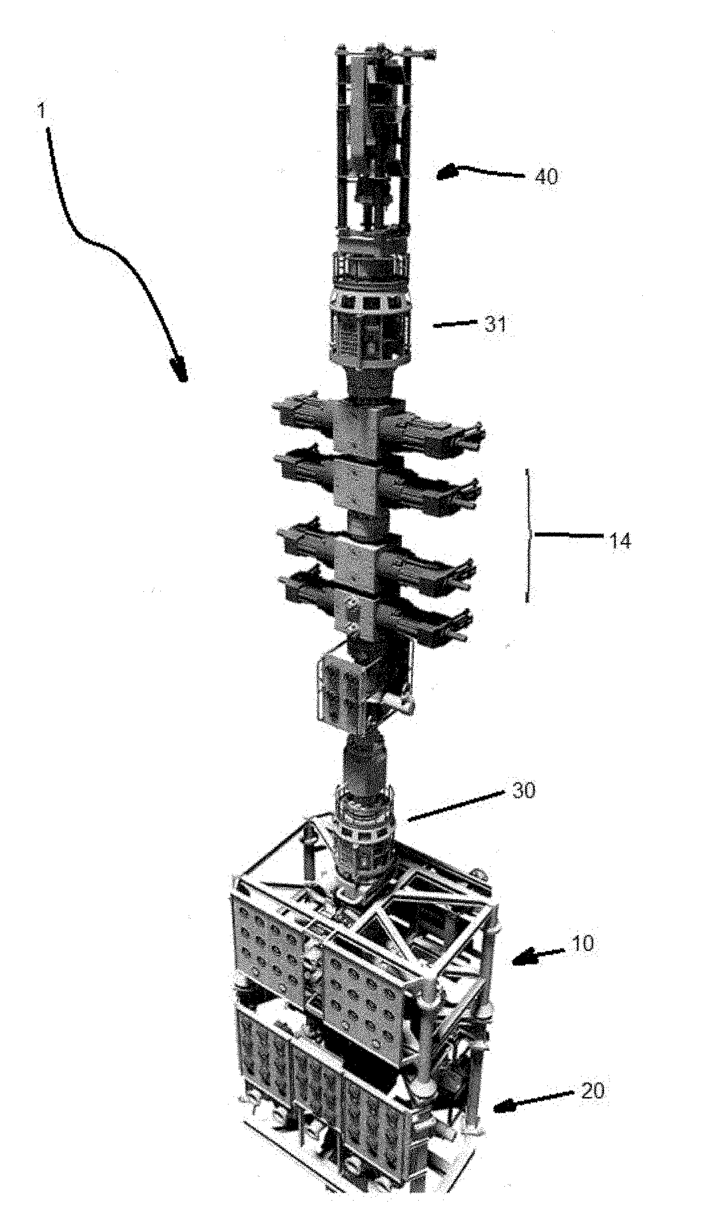
[0008] FIG. 1 is a view in partial perspective of a first exemplary system;
[0009] FIG. 2 is a second in partial perspective of a second exemplary system; and
[0010] FIG. 3 is a view in partial perspective of an exemplary system showing a fluid source.
BRIEF DESCRIPTION OF EXEMPLARY EMBODIMENTS
[0011] Referring now to FIG. 1, open water coiled tubing sealer 1, useful to control hydrostatic pressure and wellbore/pipeline pressures, comprises upper well control assembly 10, comprising a first geometric orientation; lower well control assembly 20 in fluid communication with upper well control assembly 10, where lower well control assembly 20 comprises a second geometric orientation substantially inverted to the first orientation; and quick disconnect connector 30 in fluid communication with upper well control assembly 10.
[0012] In typical embodiments, open water coiled tubing sealer 1 further comprises one or more electrically powered subsea assist jacks 40 which are operatively connected to quick disconnect connector 30 and a controller operatively in communication with the electrically powered subsea assist jack. Previously this equipment was to be hydraulically controlled (which is the industry norm). Typically, electrically powered subsea assist jacks 40 are controlled using three phase electric power and electric motors with a feedback loop of electronic communication over a power connector which may comprise or otherwise interface with umbilical 110 or the like. Thus, instead of hydraulic motors driving the jack cylinders, these would be replaced with electric motors utilizing a power convertor operatively in communication with the power connector to handle the speed and direction through a main umbilical, such as umbilical 110, to subsea fluid source 100 which may be part of a subsea control skid.
[0013] The same thing could be done with one or more slip bowls, i.e. electric motors could replace hydraulic motors to activate and de-activate the slips. One or more electronic sensors, which can comprise proximity switches or similar equipment, can be utilized to provide feedback for control such as for closing and opening the slip bowls along with one or more position sensors to provide feedback on the position of the cylinders/roller bearing screw jacks, e.g. electrically powered subsea assist jacks 40, which are operatively connected to the electric motors.
[0014] Power and communication may be achieved through umbilical 120 to intervention system 200.
[0015] In certain embodiments open water coiled tubing sealer 1 further comprises one or more coiled tubing packers 50 disposed intermediate electrically powered subsea assist jacks 40 and quick disconnect connector 30.
[0016] Typically, upper well control assembly 10 comprises a plurality of control assemblies 12. Similarly, lower well control assembly 20 may also comprise a plurality of control assemblies 22 which may be the same as or similar to control assemblies 12. Where upper well control assembly 10 comprises the plurality of control assist assemblies 12, these may be arranged into pairs, which may be arranged redundantly and/or cooperatively or the like. Similarly, where lower well control assembly 20 comprises the plurality of control assist assemblies 22, these may also be arranged into pairs, which may be arranged redundantly and/or cooperatively or the like.
[0017] Upper well control assembly 10 may further comprise one or more inverted strippers 14. Upper well control assembly 10 may also further comprise one or more packer elements 16. Such packer elements 16 may be other otherwise comprise a subsea replaceable packer.
[0018] As illustrated in FIGS. 1 and 2, quick disconnect connector 30 may be located intermediate strippers 14 and upper well control assembly 10 and a second quick disconnect connector, quick disconnect connector 31 (FIG. 2) may be optionally present and located intermediate electrically powered subsea assist jacks 40 and strippers 14.
[0019] Similarly, lower well control assembly 20 may comprise one or more strippers 24. As with upper well control assembly 10, lower well control assembly 20 may also further comprise one or more packer elements 26 which may be other otherwise comprise a subsea replaceable packer.
[0020] In the operation of exemplary embodiments, hydrostatic pressure and wellbore/pipeline pressures may be controlled in a system that comprises subsea fluid source 100 which utilizes riserless open water coiled tubing system 1. In general, the method comprises operatively connecting open water coiled tubing sealer 1, as described above, to subsea fluid source 100 and an electrical power source and using upper well control assembly 10 and lower well control assembly 20 to pressurize a predetermined set of annular cavities existing between upper well control assembly 10 and lower well control assembly packer assembly 20. Hydrostatic pressure is then enabled to assist sealing upper well control assembly 10. Fluid pressure from subsea fluid source 100 may be used to assist sealing lower well control assembly 10. A predetermined amount of hydrostatic pressure may then be maintained with very low well/pipeline pressure and handling the subsequent differential pressure.
[0021] Hydrostatic pressure of up to a first pressure of around 4500 psi may be used. Further, source fluid pressures from zero to around 10000 psi may be used.
[0022] One or more pairs of bi-directional sealing elements may be set up in pairs as described above.
[0023] Where upper well control assembly 10 comprises a plurality of packer assemblies 16 with hydrostatic control assist and lower well assembly 20 comprises a plurality of packer units 25 which are adapted for assisting well control, the method further comprising using hydro-cushions to pressurize the annular cavities between the dual sets of packers.
[0024] Where the system further comprises subsea fluid source 100 such as a monoethylene glycol (MEG) fluid source or the like, the method may further comprise controlling the pressure using pairs of sealing elements with full backup for each system to enable the hydrostatic pressure to assist sealing the upper pair of packers and the wellbore pressure to assist sealing the lower pair of packers. In embodiments, full backup comprises using a duplicate set of sealing elements, each set of sealing elements further comprising one or more packers 16,26.
[0025] In embodiments, packers 16,26 may be replaced subsea, thereby allowing continuous operations without pulling open water coiled tubing sealer 1 back to surface to replace the packers.
[0026] It is noted that although various arrangements can be used, the basic arrangement is a first stripper/packer arranged in a first position relative to fluid flow and a second stripper/packer, essentially the same or similar to the first stripper/packer, fluidly coupled to the first stripper/packer but inverted with respect the first stripper/packer alignment. This can entail a plurality of each such stripper/packer units, e.g. two first stripper/packer assemblies with hydrostatic control assist and one or more second stripper/packer units for well control assist with hydro-cushions to pressurize the annular cavities between the dual sets of packers. By doing this, hydrostatic pressure is enabled to assist sealing the upper stripper/packers and the wellbore pressure to assist sealing the lower stripper/packers. It has been found that adding additional stages as described herein, splitting them into pairs, and then inverting one pair from the other so using ambient and well pressure to energize and seal.
[0027] As opposed to current systems for only surface application and seal coiled tubing from wellbore or pipeline pressure with only ambient pressure at surface, using the methods described above, dynamic/static sealing of coiled tubing subsea, such as for pipeline and well access, may be accomplished with hydrostatic conditions of up to around 10,000 ft water depth while maintaining wellbore or pipeline pressures up to around 10,000 psi.
[0028] The foregoing disclosure and description of the inventions are illustrative and explanatory. Various changes in the size, shape, and materials, as well as in the details of the illustrative construction and/or an illustrative method may be made without departing from the spirit of the invention.
* * * * *
D00000
D00001
D00002
D00003
XML
uspto.report is an independent third-party trademark research tool that is not affiliated, endorsed, or sponsored by the United States Patent and Trademark Office (USPTO) or any other governmental organization. The information provided by uspto.report is based on publicly available data at the time of writing and is intended for informational purposes only.
While we strive to provide accurate and up-to-date information, we do not guarantee the accuracy, completeness, reliability, or suitability of the information displayed on this site. The use of this site is at your own risk. Any reliance you place on such information is therefore strictly at your own risk.
All official trademark data, including owner information, should be verified by visiting the official USPTO website at www.uspto.gov. This site is not intended to replace professional legal advice and should not be used as a substitute for consulting with a legal professional who is knowledgeable about trademark law.