Nickel-iron-aluminum-chromium Based Alloys, And Products Made Therefrom
Tang; Zhi ; et al.
U.S. patent application number 15/727369 was filed with the patent office on 2019-01-24 for nickel-iron-aluminum-chromium based alloys, and products made therefrom. The applicant listed for this patent is ARCONIC INC.. Invention is credited to Yijia Gu, Lynette M. Karabin, Xuan Nguyen-Dinh, Daniel J. Sauza, Zhi Tang, Wei Wang, Cagatay Yanar.
| Application Number | 20190024225 15/727369 |
| Document ID | / |
| Family ID | 62195658 |
| Filed Date | 2019-01-24 |


View All Diagrams
| United States Patent Application | 20190024225 |
| Kind Code | A1 |
| Tang; Zhi ; et al. | January 24, 2019 |
NICKEL-IRON-ALUMINUM-CHROMIUM BASED ALLOYS, AND PRODUCTS MADE THEREFROM
Abstract
The present disclosure relates to new nickel-iron-aluminum-chromium based alloys. Generally, the new alloys contain 20-40 at. % Ni, 15-40 at. % Fe, 5-20 at % Al, and 5-26 at. % Cr, the balance being optional incidental elements and unavoidable impurities. Generally, methods for producing the new alloys include one or more of heating a mixture above its liquidus temperature, then cooling the mixture below its solidus temperature, optionally hot and/or cold working the solid material into a final product form, then heating and quenching the solid material, and precipitation hardening the solid material.
| Inventors: | Tang; Zhi; (Pittsburgh, PA) ; Karabin; Lynette M.; (Ruffs Dale, PA) ; Gu; Yijia; (Pittsburgh, PA) ; Yanar; Cagatay; (Pittsburgh, PA) ; Wang; Wei; (State College, PA) ; Nguyen-Dinh; Xuan; (Monroeville, PA) ; Sauza; Daniel J.; (Pittsburgh, PA) | ||||||||||
| Applicant: |
|
||||||||||
|---|---|---|---|---|---|---|---|---|---|---|---|
| Family ID: | 62195658 | ||||||||||
| Appl. No.: | 15/727369 | ||||||||||
| Filed: | October 6, 2017 |
Related U.S. Patent Documents
| Application Number | Filing Date | Patent Number | ||
|---|---|---|---|---|
| PCT/US2017/054559 | Sep 29, 2017 | |||
| 15727369 | ||||
| 62402409 | Sep 30, 2016 | |||
| 62523101 | Jun 21, 2017 | |||
| Current U.S. Class: | 1/1 |
| Current CPC Class: | C22F 1/10 20130101; C21D 8/00 20130101; C22C 30/00 20130101; C22C 1/0433 20130101; C21D 6/02 20130101; C21D 2211/004 20130101; C22C 19/058 20130101; B22F 1/0055 20130101; C22C 38/00 20130101; C22F 1/002 20130101; C21D 2211/001 20130101; C21D 6/004 20130101; C22C 33/0285 20130101; B33Y 80/00 20141201 |
| International Class: | C22F 1/10 20060101 C22F001/10; C22C 19/05 20060101 C22C019/05; C22F 1/00 20060101 C22F001/00; C22C 30/00 20060101 C22C030/00 |
Claims
1. A method comprising: (a) heating a mixture above its liquidus temperature, wherein the mixture comprises: (i) 20-40 at. % Ni; (ii) 15-40 at. % Fe; (iii) 5-20 at % Al; and (iv) 5-26 at. % Cr; (b) cooling the mixture below its solidus temperature, thereby forming a solid material having a mixed fcc+bcc crystalline structure, wherein the mixture includes a sufficient amount of the Ni, the Fe, the Al and the Cr to realize the mixed fcc+bcc crystalline structure; (c) optionally hot and/or cold working the solid material into a final product form; (d) heating the solid material, thereby dissolving at least some second phase particles within the solid material; (e) quenching the solid material; and (f) precipitation hardening the solid material, thereby forming precipitates within the mixed fcc+bcc crystalline structure of the solid material.
2. The method of claim 1, wherein the mixture comprises 60-77 at. % Ni+Fe.
3. The method of claim 2, wherein the mixture comprises 23-40 at. % Al+Cr.
4. The method of claim 3, wherein the mixture includes 27.5-40 at. % Ni.
5. The method of claim 4, wherein the mixture includes 25-40 at. % Fe.
6. The method of claim 5, wherein the mixture includes at least 12 at. % Cr.
7. The method of claim 6, wherein the mixture includes not greater than 16 at. % Al.
8. The method of claim 1, wherein the balance of the solid material is optional incidental elements and unavoidable impurities, wherein the optional incidental elements comprise: up to 15 at. %, in total, of one or more of cobalt (Co), copper (Cu), molybdenum (Mo), manganese (Mn), and tungsten (W); up to 10 at. %, in total, of one or more of niobium (Nb), tantalum (Ta), and titanium (Ti); up to 10 at. % carbon (C); up to 5 at. % of silicon (Si); up to 5 at. %, in total, of one or more of vanadium (V) and hafnium (Hf); up to 2 at. %, in total, of one or more of boron (B) and zirconium (Zr); up to 1 at. %, in total, of magnesium (Mg), calcium (Ca), cerium (Ce) and lanthanum (La); up to 1 at. % of nitrogen (N); and up to 10 vol. % of at least one ceramic material.
9. The method of claim 8, wherein the mixture includes at least 0.5 at. % Ti.
10. The method of claim 9, wherein a combined amount of Al plus Ti in the mixture is not greater than 20 at. %.
11. The method of claim 1, wherein the solid material comprises an alloy matrix and wherein the alloy matrix comprises at least 3.0 vol. % of fcc crystalline structures.
12. The method of claim 11, wherein the cooling the mixture below its solidus temperature step comprises first forming fcc crystalline structures from the mixture and then forming bcc crystalline structures.
13. The method of claim 12, wherein the solid material comprises dendritic fcc crystalline structures.
14. The method of claim 1, wherein the heating step (a) comprises selectively heating a portion of a powder comprising the mixture via a laser, thereby forming a molten pool having at least Ni, Fe, Al, and Cr therein; and wherein the cooling step (b) comprises cooling the molten pool at a cooling rate of at least 1000.degree. C. per second.
15. The method of claim 1, wherein step (c) is completed and the method includes hot and/or cold working the solid material into the final product form; wherein the heating step (d) comprises heating the final product form, thereby dissolving at least some second phase particles within the final product form; wherein the quenching step (e) comprises quenching the final product form; and wherein the precipitating hardening step (f) comprises precipitation hardening the final product form, thereby forming precipitates within the mixed fcc+bcc crystalline structure of the final product form.
16. The method of claim 15, wherein the forming precipitates comprises forming at least 0.5 vol. % of the precipitates within the mixed fcc+bcc crystalline structure of the final product form.
17. The method of claim 16, wherein the precipitates comprise at least one of L1.sub.2, L2.sub.1, B2, Laves, delta, and D0.sub.22.
18. The method of claim 16, wherein the forming precipitates comprise forming at least one of L1.sub.2, L2.sub.1, B2, delta, and D0.sub.22, and wherein the final product form is essentially free of Laves precipitates.
19. The method of claim 1, wherein the mixture comprises 20-40 at. % Ni, 20-40 at. % Fe, 5-16 at % Al, 8-26 at. % Cr, and 0.5-10 at. % Ti.
20. The method of claim 1, wherein the mixture comprises 20-40 at. % Ni, 20-35 at. % Fe, 6-14 at % Al, and 18-22 at. % Cr, and 1.0-7.0 at. % Ti.
Description
CROSS-REFERENCE TO RELATED APPLICATIONS
[0001] This patent application is a continuation of International Patent Application No. PCT/US2017/054559, filed Sep. 29, 2017, entitled "NICKEL-IRON-ALUMINUM-CHROMIUM BASED ALLOYS, AND PRODUCTS MADE THEREFROM", which claims the benefit of priority of U.S. Provisional Patent Application No. 62/402,409, filed Sep. 30, 2016, and of U.S. Provisional Patent Application No. 62/523,101 filed Jun. 21, 2017, both entitled "MIXED CRYSTALLINE NICKEL-IRON BASED ALLOYS, AND PRODUCTS MADE THEREFROM", each of which is incorporated herein by reference in its entirety.
BACKGROUND
[0002] INCONEL.RTM. 625 is a nickel-based alloy having chromium, niobium (plus tantalum), and molybdenum as alloying elements. INCONEL.RTM. 718 is another nickel-based alloy having iron, chromium, niobium (plus tantalum), titanium, aluminum, and molybdenum as alloying elements.
SUMMARY OF THE DISCLOSURE
[0003] Broadly, the present patent application relates to new nickel-iron-aluminum-chromium based alloys ("the new materials"). Particularly, the new materials may comprise an alloy matrix having both face-centered cubic (fcc) and body-centered cubic (bcc) crystalline structures ("mixed fcc+bcc crystalline structure"), or a matrix consisting essentially of fcc crystalline structures ("fcc-only crystalline structure") immediately below the solidus temperature of the material. As known to those skilled in the art, and as shown in FIG. 1, a body-centered cubic unit cell has atoms at each of the eight corners of a cube plus one atom in the center of the cube. Each of the corner atoms is the corner of another cube so the corner atoms are shared among eight unit cells. A face-centered cubic (fcc) unit cell has atoms at each of the eight corners of a cube plus one atom on each face of the cube. Each of the corner atoms is the corner of another cube so the corner atoms are shared among eight unit cells, while the face atoms are shared with two unit cells.
[0004] Due to the unique compositions described herein, the new materials may realize a mixed crystalline structure having a mixed fcc+bcc crystalline structure or an fcc-only crystalline structure immediately below the solidus temperature of the material. The new materials may also have a narrow equilibrium freezing range (e.g., for restricting microsegregation during solidification), making them suitable for production through conventional ingot processing, as well as powder metallurgy, shape casting, additive manufacturing, and combinations thereof (hybrid processing). The new materials may find use in many applications, including use in elevated temperature environments (e.g., 400.degree. C.-800.degree. C.).
[0005] In some instances, the new materials may also/alternatively include a B2 crystalline structure. As used herein "B2" means a crystalline structure having a bcc unit cell style, but with the center atom being different than the corner atoms. For instance, as shown in FIG. 2, a B2 unit cell may include atoms of a first element (X) at each of its eight corners, while the B2 unit cell may include an atom of a second element (Y) at its center. Each of the eight corners include 1/8 of the first element (X), corresponding to a full atom of the first element (X). Thus, the X and Y elements have (generally) a 1:1 ratio. All references to "bcc" herein mean both traditional bcc crystalline structures and B2 crystalline structures, unless the context clearly indicates otherwise.
[0006] The new materials generally include nickel (Ni) and iron (Fe) as the main alloying elements, providing the base fcc crystalline structure. Aluminum (Al) and chromium (Cr) are secondary alloying elements. Aluminum may facilitate realization of a mixed fcc+bcc crystalline structure, or an fcc-only crystalline structure. Chromium may facilitate corrosion resistance of the material. Optional incidental elements may be used with the alloy, as described in further detail below.
I. Nickel, Iron, Aluminum and Chromium
[0007] In one approach, a new material includes 20-40 at. % Ni, 15-40 at. % Fe, 5-20 at. % Al, and 5-26 at. % Cr. In one embodiment, a new material includes a sufficient amount of the Ni, Fe, Al and Cr to realize a mixed fcc+bcc crystalline structure. In another embodiment, a new material includes a sufficient amount of the Ni, Fe, Al, and Cr to realize a matrix consisting essentially of fcc crystalline structures (an "fcc only" microstructure). In one embodiment, a new material includes 20-40 at. % Ni, 15-40 at. % Fe, 8-20 at. % Al, and 5-26 at. % Cr, wherein the alloy includes a sufficient amount of the Ni, Fe, Al and Cr to realize a mixed fcc+bcc crystalline structure, or an fcc only microstructure. In one embodiment, a new material includes 20-40 at. % Ni, 20-40 at. % Fe, 10-20 at. % Al, and 5-26 at. % Cr, wherein the alloy includes a sufficient amount of the Ni, Fe, Al and Cr to realize a mixed fcc+bcc crystalline structure, or an fcc only microstructure. The material may consist of the Ni, Fe, Al, and Cr, allowing for optional incidental elements and unavoidable impurities. In one embodiment, a new material includes from 60 to 77 at. % Ni+Fe (e.g., for castability purposes). In one embodiment, a new material includes from 23 to 40 at. % Al+Cr (e.g., for castability purposes).
[0008] In one embodiment, a new material includes 25-40 at. % Ni. In one embodiment, a new material includes 27.5-40 at. % Ni. In one embodiment, a new material includes 30-40 at. % Ni. In one embodiment, a new material includes 32.5-40 at. % Ni. In one embodiment, a new material includes 32.5-37.5 at. % Ni. In another embodiment, a new material includes 25-35 at. % Ni. In yet another embodiment, a new material includes 25-32.5 at. % Ni. In another embodiment, a new material includes 27.5-32.5 at. % Ni. In one embodiment, a new material includes at least 22.5 at. % Ni. In another embodiment, a new material includes at least 25.0 at. % Ni. In yet another embodiment, a new material includes at least 27.5 at. % Ni. In yet another embodiment, a new material includes at least 30.0 at. % Ni. In one embodiment, a new material includes not greater than 37.5 at. % Ni. In another embodiment, a new material includes not greater than 35.0 at. % Ni. In yet another embodiment, a new material includes not greater 32.5 at. % Ni.
[0009] In one embodiment, a new material includes 20-40 at. % Fe. In one embodiment, a new material includes 25-40 at. % Fe. In one embodiment, a new material includes 27.5-40 at. % Fe. In one embodiment, a new material includes 30-40 at. % Fe. In one embodiment, a new material includes 32.5-40 at. % Fe. In one embodiment, a new material includes 32.5-37.5 at. % Fe. In another embodiment, a new material includes 20-35 at. % Fe. In yet another embodiment, a new material includes 22.5-35 at. % Fe. In another embodiment, a new material includes 25-35 at. % Fe. In yet another embodiment, a new material includes 27.5-35 at. % Fe. In one embodiment, a new material includes at least 22.5 at. % Fe. In another embodiment, a new material includes at least 25.0 at. % Fe. In yet another embodiment, a new material includes at least 27.5 at. % Fe. In another embodiment, a new material includes at least 30.0 at. % Fe. In one embodiment, a new material includes not greater than 37.5 at. % Fe. In another embodiment, a new material includes not greater than 35.0 at. % Fe. In yet another embodiment, a new material includes not greater than 32.5 at. % Fe
[0010] In one embodiment, a new material includes 5-20 at. % Al. Using an appropriate amount of aluminum may facilitate working (e.g., hot working) of the product to an appropriate final product form and/or may facilitate an fcc-first solidification pathway (described below). In one embodiment, a new material includes 5-18 at. % Al. In another embodiment, a new material includes 5-16 at. % Al. In yet another embodiment, a new material includes 5-15 at. % Al. In another embodiment, a new material includes 6-15 at. % Al. In one embodiment, a new material includes 10-20 at. % Al. In yet another embodiment, a new material includes 6-14 at. % Al. In one embodiment, a new material includes 11-19 at. % Al. In one embodiment, a new material includes 11-18 at. % Al. In one embodiment, a new material includes 11-17 at. % Al. In one embodiment, a new material includes 12-16 at. % Al. In one embodiment, a new material includes 12-15 at. % Al. In one embodiment, a new material includes at least 6 at. % Al. In another embodiment, a new material includes at least 7 at. % Al. In yet another embodiment, a new material includes at least 8 at. % Al. In another embodiment, a new material includes at least 9 at. % Al. In yet another embodiment, a new material includes at least 10 at. % Al. In one embodiment, a new material includes not greater than 18 at. % Al. In another embodiment, a new material includes not greater than 16 at. % Al. In yet another embodiment, a new material includes not greater than 15 at. % Al. In another embodiment, a new material includes not greater than 14 at. % Al.
[0011] In one embodiment, a new material includes 8-26 at. % Cr. In one embodiment, a new material includes 12-26 at. % Cr. In one embodiment, a new material includes 17-26 at. % Cr. In another embodiment, a new material includes 18-26 at. % Cr. In one embodiment, a new material includes 14-26 at. % Cr. In one embodiment, a new material includes 16-24 at. % Cr. In one embodiment, a new material includes 18-22 at. % Cr. In one embodiment, a new material includes at least 8 at. % Cr. In another embodiment, a new material includes at least 12 at. % Cr. In yet another embodiment, a new material includes at least 16 at. % Cr. In another embodiment, a new material includes at least 17 at. % Cr. In yet another embodiment, a new material includes at least 18 at. % Cr. In one embodiment, a new material includes not greater than 24 at. % Cr. In another embodiment, a new material includes not greater than 22 at. % Cr.
[0012] In one embodiment, the amount of aluminum and chromium is within the scope of both:
[0013] (1) Cr.gtoreq.-3.5*Al+44; and
[0014] (2) Cr.ltoreq.-4*Al+90
where the Cr and Al are expressed in at. %.
II. Optional Incidental Elements
[0015] As mentioned above, optional incidental elements may be used with the new materials described herein, provided the above-identified requirements relating to nickel, iron, aluminum, and chromium are satisfied. For instance, up to 15 at. %, in total, of one or more of cobalt (Co), copper (Cu), molybdenum (Mo), manganese (Mn), and tungsten (W) may be used, which elements may, for instance, contribute to solid solution strengthening of the alloy. Up to 10 at. %, in total, of one or more of niobium (Nb), tantalum (Ta), and titanium (Ti) may be used, which elements may, for instance, facilitate precipitation formation and/or improve stability of precipitates. Up to 10 at. % of carbon (C) may be used, and may facilitate solid interstitial solution strengthening and/or carbide strengthening. Up to 5 at. % of silicon may be used as silicon may, for instance, improve wear resistance and/or lower density. Up to 5 at. %, in total, of one or more of vanadium (V) and hafnium (Hf) may be used, which elements may, for instance, facilitate boride and/or carbide formation and/or grain boundary strengthening (e.g., in the case of hafnium). Up to 2% at. %, in total, of one or more of boron (B), and zirconium (Zr) may be used, which elements may facilitate formation of boron and/or carbide, and may facilitate grain boundary strengthening. Up to 1 at. %, in total, of magnesium (Mg), calcium (Ca), cerium (Ce) and lanthanum (La) may be used, which elements may facilitate casting of the alloys. Up to 1 at. % of nitrogen (N) may be used as nitrogen may, for instance, facilitate stabilization of the fcc structure and/or may improve corrosion resistance.
[0016] As noted above, up to 15 at. %, in total, of one or more of cobalt (Co), copper (Cu), molybdenum (Mo), manganese, and tungsten (W) may be used, which elements may, for instance, contribute to solid solution strengthening of the alloy. In one embodiment, an alloy includes up to 10 at. % Co, wherein a sufficient amount of cobalt is present to facilitate solid solution strengthening and/or second phase strengthening, as compared to the same alloy without cobalt. In one embodiment, an alloy includes at least 0.5 at. % Co. In one embodiment, the alloy includes not greater than 5.0 at. % Co. In another embodiment, the alloy includes not greater than 1.0 at. % Co. In another embodiment, the alloy is essentially free of cobalt, containing cobalt only as an impurity.
[0017] In one embodiment, an alloy includes up to 10 at. % Cu, wherein a sufficient amount of copper is present to facilitate solid solution strengthening and/or second phase strengthening, as compared to the same alloy without copper. In one embodiment, an alloy includes at least 0.5 at. % Cu. In another embodiment, the alloy includes not greater than 5.0 at. % Cu. In yet another embodiment, the alloy includes not greater than 1.0 at. % Cu. In another embodiment, the alloy is essentially free of copper, containing copper only as an impurity.
[0018] In one embodiment, an alloy includes up to 10 at. % Mo, wherein a sufficient amount of molybdenum is present to facilitate solid solution strengthening and/or second phase strengthening, as compared to the same alloy without molybdenum. In one embodiment, at least some molybdenum is included within the fcc phase of the alloy. In one embodiment, an alloy includes at least 0.5 at. % Mo. In one embodiment, the alloy includes not greater than 5.0 at. % Mo. In another embodiment, the alloy includes not greater than 1.0 at. % Mo. In another embodiment, the alloy is essentially free of molybdenum, containing molybdenum only as an impurity.
[0019] In one embodiment, an alloy includes up to 15.0 at. % of Mn. Manganese may be used, for instance, to reduce the density of the final product to be formed. Manganese may, for instance, facilitate precipitate formation and/or improve stability of precipitates. Furthermore, manganese may in some cases be substituted for some amount of the iron and/or nickel content (e.g., up to 15.0 at. %). In one embodiment, manganese is included in a new material (e.g., at least 0.5 at. % Mn is used). In one embodiment, an alloy includes not greater than 10.0 at. % Mn. In another embodiment, an alloy includes not greater than 5.0 at. % Mn. In yet another embodiment, an alloy includes not greater than 1.0 at. % Mn. In one embodiment, at least some manganese is substituted for iron. In another embodiment, the alloy is essentially free of manganese, containing manganese only as an impurity.
[0020] In one embodiment, an alloy includes up to 5.0 at. % W, wherein a sufficient amount of tungsten is present to facilitate solid solution strengthening and/or second phase strengthening, as compared to the same alloy without tungsten. In one embodiment, an alloy includes at least 0.5 at. % W. In one embodiment, at least some tungsten is included within the fcc phase of the alloy. In one embodiment, an alloy includes not greater than 3.0 at. % W. In another embodiment, an alloy includes not greater than 1.0 at. % W. In another embodiment, the alloy is essentially free of tungsten, containing tungsten only as an impurity.
[0021] As noted above, up to 10 at. %, in total, of one or more of niobium (Nb), tantalum (Ta), and titanium (Ti) may be used, which elements may, for instance, facilitate precipitation formation and/or improve stability of precipitates. In one embodiment, the alloy includes up to 5.0 at. % Nb, wherein a sufficient amount of niobium is present to facilitate precipitation of niobium-containing precipitates or second phase particles (e.g., A.sub.3Nb precipitates, A.sub.6Nb[Al,Ti] precipitates, where A is one of Ni, Fe, and Co, and equivalent substitutable elements), wherein a sufficient volume of niobium-containing precipitates are present to provide precipitation hardening/strengthening of bcc, when used. In one embodiment, an alloy includes at least 0.5 at. % Nb. In another approach, the amount of niobium added may facilitate precipitation strengthening, but is restricted such that the amount of Laves precipitates within the final product is not greater than 0.5 vol. %. In one embodiment, the alloy includes not greater than 4.0 at. % Nb. In another embodiment, the alloy includes not greater than 3.0 at. % Nb. In another embodiment, the alloy is essentially free of niobium, containing niobium only as an impurity.
[0022] In one embodiment, the alloy includes not greater than 3 at. % Ta, wherein a sufficient amount of tantalum is present to facilitate precipitate stability (e.g., high solvus temperatures)/strengthening of bcc. In one embodiment, an alloy includes at least 0.5 at. % Ta. In another embodiment, the alloy includes not greater than 2.0 at. % Ta. In another embodiment, an alloy includes not greater than 1.0 at. % Ta. In another embodiment, the alloy is essentially free of tantalum, containing tantalum only as an impurity.
[0023] In one embodiment, the alloy includes up to 10.0 at. % Ti. Using titanium may reduce density, and may contribute to strengthening of the alloy. However, too much titanium may cause embrittlement (e.g., cracking). In one embodiment, the alloy includes at least some titanium (e.g., at least 0.5 at. % Ti), wherein a sufficient amount of titanium is present to facilitate precipitation of X.sub.3(Ti, Y) precipitates, where X is one of Ni, Fe, and Co, and equivalent substitutable elements, where Y is any of Al, Nb, and Ta, and equivalent suitable elements, and wherein a sufficient volume of X.sub.3(Ti, Y) precipitates are present in the alloy to provide precipitation hardening. In one embodiment, due to at least the titanium content, the alloy includes at least some precipitate phases, such as X.sub.3(Ti, Y), to facilitate high solvus temperature(s). In one approach, the amount of X.sub.3(Ti, Y) precipitates in the alloy is at least 5 vol. %. In another embodiment, the amount of X.sub.3(Ti, Y) precipitates in the alloy is at least 10 vol. %. In yet another embodiment, the amount of X.sub.3(Ti, Y) precipitates in the alloy is at least 15 vol. %. In one embodiment, the alloy includes at least 0.5 at. % Ti. In another embodiment, the alloy includes at least 1.0 at. % Ti. In yet another embodiment, the alloy includes at least 2.0 at. % Ti. In another embodiment, the alloy includes at least 3.0 at. % Ti. In one embodiment, the alloy includes not greater than 9.0 at. % Ti. In another embodiment, the alloy includes not greater than 8.0 at. % Ti. In yet another embodiment, the alloy includes not greater than 7.0 at. % Ti. In another embodiment, the alloy includes not greater than 6.0 at. % Ti. In another embodiment, the alloy includes not greater than 5.0 at. % Ti. In one embodiment, the alloy includes 1.0-7.0 at. % Ti. In one embodiment, the alloy is essentially free of titanium, containing titanium only as an impurity.
[0024] As described below, an "fcc-first" solidification pathway may facilitate the production of products having improved properties, such as, reduced cracking during additive manufacturing and/or casting, and improved tensile properties, among others. For instance, in one approach, the amount of aluminum within the alloy is sufficient to realize an fcc-first solidification pathway where fcc forms first during solidification of a melt. In another embodiment, titanium is also used in the alloy and in combination with aluminum in an amount sufficient to realize an fcc-first solidification pathway. In this regard, appropriate amounts of titanium plus aluminum may facilitate the production of alloy products having improved properties, such as, reduced cracking during additive manufacturing and/or casting, and/or improved tensile properties, among others. For instance, an appropriate amount of titanium (e.g., from 0.5 to 10 at. %, depending on the aluminum content) may facilitate the realization of an fcc-first solidification pathway. In one approach, the total amount of Al+Ti (in at. %) is sufficient to realize a fcc-first solidification pathway, and is sufficient to avoid embrittlement (e.g., cracking). In one embodiment, the total amount of Al+Ti (in at. %) is not greater than 20 at. % (i.e., at. % Al+at. % Ti.ltoreq.20 at. %). In another embodiment, the total amount of Al+Ti (in at. %) is not greater than 18 at. %. In yet another embodiment, the total amount of Al+Ti (in at. %) is not greater than 16 at. %. In one embodiment, the total amount of Al+Ti (in at. %) is at least 6 at. % (i.e., at. % Al+at. % Ti.gtoreq.6 at. %). In another embodiment, the total amount of Al+Ti (in at. %) is at least 7 at. %. In yet another embodiment, the total amount of Al+Ti (in at. %) is at least 8 at. %. In another embodiment, the total amount of Al+Ti (in at. %) is at least 9 at. %. In another embodiment, the total amount of Al+Ti (in at. %) is at least 10 at. %. In one embodiment, the total amount of Al+Ti (in at. %) is from 6 to 18 at. %. In another embodiment, the total amount of Al+Ti (in at. %) is from 7 to 17 at. %. In yet another embodiment, the total amount of Al+Ti (in at. %) is from 7 to 16 at. %.
[0025] As noted above, up to 10 at. % carbon may be used in the alloy. In one embodiment, the alloy includes a sufficient amount of carbon to facilitate interstitial solid solution strengthening (hardening). In another embodiment, the alloy includes a sufficient amount of carbon to facilitate formation of carbides (e.g., MC, M.sub.23C.sub.6, M.sub.7C.sub.3 compounds, where M is a metal, such as any of Fe, Al, and Cr and potentially Mo and Ti, if present in the alloy), where a sufficient volume of carbides is present to provide carbide strengthening (and with or without interstitial solid solution strengthening). In one embodiment, a sufficient amount of carbon is used to achieve both interstitial solid solution strengthening and carbide precipitation. However, too much carbon may cause embrittlement (e.g., cracking; low ductility) of the alloy. Thus, in one embodiment the amount of carbon is restricted to avoid embrittlement. In one embodiment, the alloy includes at least 0.05 at. % C. In another embodiment, the alloy includes at least 0.2 at. % of C. In yet another embodiment, the alloy includes at least 0.5 at. % of C. In yet another embodiment, the alloy includes at least 1.0 at. % of C. In another embodiment, the alloy includes at least 2.0 at. % of C. In another embodiment, the alloy includes at least 3.0 at. % of C. In one embodiment, the alloy includes not greater than 8.0 at. % C. In another embodiment, the alloy includes not greater than 7.0 at. % C. In yet another embodiment, the alloy includes not greater than 6.0 at. % C. In another embodiment, the alloy includes not greater than 5.0 at. % C. In one embodiment, an alloy includes from 1-10 at. % C. In another embodiment, an alloy includes from 2-9 at. % C. In yet another embodiment, an alloy includes 3-9 at. % C. In another embodiment, an alloy includes 3-8 at. % C. In one embodiment, a sufficient amount of carbon is used to restrict/prevent cracking in a bcc-first solidification pathway product. In other embodiments, the alloy is essentially free of carbon, containing carbon only as an impurity.
[0026] As noted above, up to 5.0 at. % of silicon may be used as silicon may, for instance, improve wear resistance and/or lower density. In one embodiment, the alloy includes up to 5.0 at. % Si, wherein a sufficient amount of silicon is present to facilitate precipitation of B2 phase, for higher hardness and better wear resistance (e.g., may facilitate formation of B2 by other elements), and/or facilitate solid solution strengthening and/or to realize lower density. In one embodiment, the alloy includes at least 0.05 at. % of silicon. In one embodiment, the alloy includes not greater than 3.0 at. % of silicon. In another embodiment, the alloy includes not greater than 1.0 at. % of silicon. In another embodiment, the alloy is essentially free of silicon, containing silicon only as an impurity.
[0027] As noted above, up to 5.0 at. %, in total, of one or more of vanadium (V) and hafnium (Hf) may be used, which elements may, for instance facilitate boride and/or carbide formation and/or grain boundary strengthening (e.g., in the case of hafnium). In one embodiment, the alloy includes not greater than 3.0 at. % in total of V and Hf. In another embodiment, the alloy includes not greater than 1.0 at. % in total of V and Hf. In one embodiment, the alloy includes at least 0.10 at. % Hf and/or V. In another embodiment, the alloy includes at least 0.15 at. % Hf and/or V.
[0028] In one embodiment, the alloy includes up to 2.0 at. % V. Vanadium may interact with carbon to form vanadium carbides, which may improve high temperature strength and creep resistance. In one embodiment, the alloy includes up to 1.0 at. % V. In one embodiment, the alloy includes up to 0.5 at. % V. In another embodiment, the alloy is essentially free of vanadium, containing vanadium only as an impurity.
[0029] In one embodiment, the alloy includes up to 2.0 at. % Hf Hafnium may interact with carbon to form hafnium carbides, which may improve high temperature strength and creep resistance. In one embodiment, the alloy includes up to 1.0 at. % Hf. In one embodiment, the alloy includes up to 0.5 at. % Hf. In another embodiment, the alloy is essentially free of hafnium, containing hafnium only as an impurity.
[0030] As noted above, up to 2% at. %, in total, of one or more of boron (B) and zirconium (Zr) may be used, which elements may facilitate formation of borides and/or may facilitate grain boundary strengthening. In one embodiment, the alloy includes up to 1 at. %, in total, of one or more of the B and Zr. In another embodiment, the alloy includes up to 0.75 at. %, in total, of one or more of the B and Zr. In one embodiment, the alloy includes at least 0.05 at. % of B and/or Zr.
[0031] In one embodiment, the alloy includes up to 2.0 at. % Zr. In another embodiment, the alloy includes up to 1.0 at. % Zr. In yet another embodiment, the alloy includes up to 0.75 at. % Zr. In other embodiments, the alloy is essentially free of zirconium, containing zirconium only as an impurity.
[0032] In one embodiment, the alloy includes up to 2.0 at. % B, wherein a sufficient amount of boron is present to facilitate formation of borides (e.g., M.sub.3B.sub.2, where M is a metal, such as any of Ni, Fe, or Cr, and potentially Mo and Ti, if present in the alloy), where a sufficient volume of borides is present to provide boride strengthening. In one embodiment, the alloy includes at least 0.05 at. % of B. In one embodiment, the alloy includes up to 1.0 at. % B. In another embodiment, the alloy includes up to 0.75 at. % B. In other embodiments, the alloy is essentially free of boron, containing boron only as an impurity.
[0033] As noted above, up to 1.0 at. %, in total, of magnesium (Mg), calcium (Ca), cerium (Ce) and lanthanum (La) may be used, which elements may facilitate casting of the alloys. Up to 1.0 at. % of nitrogen (N) may be used as nitrogen may, for instance, facilitate stabilization of the fcc structure and/or may improve corrosion resistance. When purposefully used, an alloy includes at least 0.05 at. % of the Mg, Ca, Ce, La, or N. In one embodiment, the alloy is essentially free of magnesium, containing magnesium only as an impurity. In one embodiment, the alloy is essentially free of calcium, containing calcium only as an impurity. In one embodiment, the alloy is essentially free of cerium, containing cerium only as an impurity. In one embodiment, the alloy is essentially free of lanthanum, containing lanthanum only as an impurity. In one embodiment, the alloy is essentially free of nitrogen, containing nitrogen only as an impurity.
[0034] As noted above, up to 10 vol. % of ceramic material (defined below) may be used as ceramic material may, for instance, facilitate production of new materials having improved strength, reduced segregation, reduced thermal and solidification shrinkage, and increased ductility, among others. Furthermore, the appropriate amount of ceramic material may restrict and/or prevent cracking (e.g., during additive manufacturing). As used herein, "ceramic" means a material comprising at least one of the following compounds: TiB, TiB.sub.2, TiC, SiC, Al.sub.2O.sub.3, BC, BN, Si.sub.3N.sub.4, Al.sub.4C.sub.3, and AlN.
[0035] In one embodiment, a new material comprises at least some ceramic material. The ceramic material may facilitate, for instance, production of crack-free products. In one embodiment, a new material comprises a sufficient amount of the ceramic material to facilitate production of crack-free products. In one embodiment, the crack-free product is a crack-free additively manufactured product. The ceramic material may facilitate, for instance, production of a product having generally equiaxed grains in the microstructure. However, too much ceramic material may decrease the strength of the product. Thus, in one embodiment, a new material comprises a sufficient amount of the ceramic material to facilitate production of a crack-free product (e.g., via equiaxed grains), but the amount of ceramic material in the product is limited so that the product retains its strength (e.g., tensile yield strength (TYS) and/or ultimate tensile strength (UTS)). For instance, the amount of ceramic material may be limited such that the strength of the ceramic-containing product is within 5 ksi (e.g., 1-2 ksi) of its strength without the ceramic. In one embodiment, the ceramic material is TiB.sub.2. In one embodiment, a new material comprises at least 0.1 vol. % of ceramic material. In one embodiment, a new material comprises 0.1-10 vol. % of ceramic material. In another embodiment, a new material comprises 0.1-5 vol. % of ceramic material. In another embodiment, a new material comprises 0.1-1.0 vol. % of ceramic material (e.g., 0.05-0.5 wt. % of ceramic material).
[0036] As used herein, "equiaxed grains" means grains having an average aspect ratio of not greater than 1.5 to 1 as measured in the XY, YZ, and XZ planes as determined by the "Heyn Lineal Intercept Procedure" method described in ASTM standard E112-13, entitled, "Standard Test Methods for Determining Average Grain Size". Ceramic-containing materials that comprise equiaxed grains may realize, for instance, improved ductility and/or strength, among others, relative to the new material without the ceramic. In this regard, equiaxed grains that realize an average grain size of not greater than 20 microns may help facilitate the realization of improved ductility and/or strength, among others. In one embodiment, a new material comprises equiaxed grains, wherein the average grain size is of from 0.01 to 20 microns.
III. Processing of New Materials
[0037] In one approach, and referring now to FIG. 3, a method of producing a new material includes the steps of (100) heating a mixture comprising the new materials, and within the scope of the above-described compositions, above a liquidus temperature of the mixture, thereby forming a liquid, (200) cooling the mixture from above the liquidus temperature to below the solidus temperature, wherein, due to the cooling, the mixture forms a solid product having a mixed fcc+bcc crystalline structure, or an fcc-only crystalline structure (potentially with other phases due to microsegregation), and wherein the mixture comprises a sufficient amount of the Ni, the Fe, the Al, and the Cr, with any optional incidental elements (noted above), to realize the mixed fcc+bcc crystalline structure, or fcc-only crystalline structure. In some embodiments, a method includes (300) cooling the solid product to below a solvus temperature of a precipitate phase of the mixture (e.g., any one of L1.sub.2, L2.sub.1, B2, delta, D0.sub.22, and Laves precipitates of the material), thereby forming one or more precipitate phases within the product, wherein the mixture comprises a sufficient amount of the Ni, the Fe, the Al, and the Cr, with any optional incidental elements (noted above) to realize precipitate phase(s) within the crystalline structure.
[0038] In one embodiment, controlled cooling of the material is employed to facilitate realization of an appropriate end product. For instance, a method may include the step of (400) cooling the mixture to ambient temperature, and a method may include controlling rates of cooling during at least cooling steps (300) and (400) such that, upon conclusion of step (400), i.e., upon reaching ambient temperature, a crack-free ingot is realized. Controlled cooling may be accomplished by, for instance, using an appropriate water cooled casting mold.
[0039] As used herein, "ingot" means a cast product of any shape. The term "ingot" includes billet. As used herein, "crack-free ingot" means an ingot that is sufficiently free of cracks such that it can be used as fabricating ingot. "Fabricating ingot" means an ingot suitable for subsequent working into a final product. The subsequent working may include, for instance, hot working and/or cold working via any of rolling, forging, extrusion, as well as stress-relief by compression and/or stretching.
[0040] In one embodiment, a crack-free product, such as a crack-free ingot, may be processed, as appropriate, to obtain a final wrought product from the material. For instance, and referring now to FIGS. 3-4, steps (100)-(400) of FIG. 3, described above, may be considered a casting step (10), shown in FIG. 4, resulting in the above-described crack-free ingot. In other embodiments, the crack-free product may be a crack-free preform produced by, for instance, shape casting, additive manufacturing or powder metallurgy. In any event, the crack-free product may be further processed to obtain a wrought final product having a mixed fcc+bcc crystalline structure, or an fcc-only crystalline structure, optionally with one or more of the precipitates phases therein. This further processing may include any combination of dissolving (20) and working (30) steps, described below, as appropriate to achieve the final product form. Once the final product form is realized, the material may be precipitation hardened (40) to develop strengthening precipitates. The final product form may be a rolled product, an extruded product or a forged product, for instance.
[0041] With continued reference to FIG. 4, as a result of the casting step (10), the ingot may include some second phase particles. The method may therefore include one or more dissolving steps (20), where the ingot, an intermediate product form and/or the final product form are heated above the solvus temperature of any applicable precipitate(s) but below the solidus temperature of the material, thereby dissolving some of or all of the second phase particles. The dissolving step (20) may include soaking the material for a time sufficient to dissolve the applicable second phase particles. After the soak, the material may be cooled to ambient temperature for subsequent working. Alternatively, after the soak, the material may be immediately hot worked via the working step (30).
[0042] The working step (30) generally involves hot working and/or cold working the ingot and/or an intermediate product form. The hot working and/or cold working may include rolling, extrusion or forging of the material, for instance. The working (30) may occur before and/or after any dissolving step (20). For instance, after the conclusion of a dissolving step (20), the material may be allowed to cool to ambient temperature, and then reheated to an appropriate temperature for hot working. Alternatively, the material may be cold worked at around ambient temperatures. In some embodiments, the material may be hot worked, cooled to ambient, and then cold worked. In yet other embodiments, the hot working may commence after a soak of a dissolving step (20) so that reheating of the product is not required for hot working.
[0043] The working step (30) may result in precipitation of second phase particles. In this regard, any number of post-working dissolving steps (20) can be utilized, as appropriate, to dissolve some of or all of the second phase particles that may have formed due to the working step (30).
[0044] After any appropriate dissolving (20) and working (30) steps, the final product form may be precipitation hardened (40). The precipitation hardening (40) may include heating the final product form to above the applicable precipitate(s) solvus temperature for a time sufficient to dissolve at least some second phase particles precipitated due to the working, and then rapidly cooling (e.g., quenching) the final product form to below the applicable precipitate(s) solvus. The precipitation hardening (40) will further include holding the product at the target temperature for a time sufficient to form strengthening precipitates, and then cooling the product to ambient temperature, thereby realizing a final aged product having strengthening precipitates therein. In one embodiment, the final aged product contains .gtoreq.0.5 vol. % of the strengthening precipitates. The strengthening precipitates are preferably located within the alloy matrix, thereby conferring strength to the product through interactions with dislocations. The precipitates may facilitate an improved combination of properties such as an improved combination of strength, ductility, and/or creep resistance, among others. Suitable precipitates may include L1.sub.2, L2.sub.1, B2, delta, D0.sub.22, and Laves precipitates, among others. In one embodiment, a new material includes at least 1.0 vol. % precipitates. In one embodiment, a new material includes at least 1.0 vol. % precipitates comprising at least one of L1.sub.2, L2.sub.1, B2, delta, D0.sub.22, and Laves precipitates. In one embodiment, a new material includes at least 1.0 vol. % of L1.sub.2 precipitates. In one embodiment, the amount of Laves precipitates in the final product is not greater than 0.5 vol. %. In another embodiment, the new material is essentially free of Laves precipitates (i.e., Laves precipitates are not detected in the new material when measured by X-ray Diffraction ("XRD")).
[0045] As used herein, "Laves precipitates" means precipitates having an elemental composition of AB2, wherein A is a first element, B is a second element different than the first element, and wherein at least one of A and B is a metal. Non-limiting examples of Laves precipitates include the C14, C36, C15, and C15.sub.b phases.
[0046] As used herein, "L2.sub.1 precipitates" means precipitates having an elemental composition of A.sub.2BC, wherein A is a first element, B is a second element different than the first element, C is a third element different than the first element and the second element, and wherein at least one of A, B, and C is a metal. Non-limiting examples of L2.sub.1 precipitates include Ni.sub.2TiAl and Co.sub.2MnSi.
[0047] As used herein, "D0.sub.22 precipitates" means precipitates having a structure belonging to at least the I4/mmm space group. One non-limiting example of a D0.sub.22 precipitate may be the .gamma.'' (gamma-double-prime) phase. D0.sub.22 precipitates may have an elemental composition of A.sub.3B, wherein A is a first element, B is a second element different than the first element. Non-limiting examples of D0.sub.22 precipitates may include Al.sub.3Ti, Ni.sub.3V, and Ni.sub.3Nb, such as .gamma.''-Al.sub.3Ti, .gamma.''-Ni.sub.3V, and .gamma.''-Ni.sub.3Nb.
[0048] As used herein, "delta precipitates" means precipitates having a structure belonging to at least the Pmmn space group. Delta precipitates may have an elemental composition of A.sub.3B, wherein A is a first element, B is at least one second element different than the first element. A non-limiting example of a delta precipitate is Ni.sub.3Nb.
[0049] As used herein, "L1.sub.2 precipitates" means precipitates having a structure belonging to at least the Pm3m space group. L1.sub.2 precipitates may have an elemental composition of A.sub.3B, wherein A is a first element and B is at least one second element different than the first element. A non-limiting example of an L1.sub.2 precipitate is the .gamma.' (gamma prime) phase (e.g., .gamma.'-Ni.sub.3(Ti,Nb)).
[0050] As used herein, "B2 precipitates" means B2 phase precipitates that form as a result of precipitation hardening (40) as opposed to any B2 phase that may form as a result of casting/solidification (10).
[0051] Due to the structure and composition of the new materials, the new materials may realize an improved combination of properties, such as an improved combination of at least two of density, ductility, strength, fracture toughness, oxidation resistance, fatigue resistance, creep resistance, and elevated temperature resistance, among others. Thus, the new materials may find use in various applications, including use in elevated temperature environments (e.g., 400.degree. C.-800.degree. C.). Some specific applications include engine components (e.g., disks, turbine blades, compressor components, vanes, airfoils, nozzles, shafts, shrouds, rotors, stators, and the like), automotive or aerospace structural components, land-based turbines, nuclear applications (e.g., reactor materials), pressure vessels, oil and gas components (e.g., wellhead components, down-hole tools, safety valves) and components used in the chemical industry (e.g., heaters, evaporator tubes, condensers), among others.
[0052] The new materials described above can also be used to produce shape cast products or preforms. Shape cast products are those products that achieve their final or near final product form after the casting process. The new materials may be shape cast into any desired shape. In one embodiment, the new materials are shape cast into an elevated temperature component (e.g., shape cast into an engine component). After casting, the shape cast product may be subject to any appropriate dissolving (20) or precipitation hardening (40) steps, as described above. In one embodiment, a shape cast product consists essentially of the Ni, the Fe, the Al, and the Cr, within the scope of the compositions described above, above, with any of the optional incidental elements described above. In one embodiment, the shape cast product includes .gtoreq.0.5 vol. % of strengthening precipitates.
IV. Tailoring of Amounts of fcc and bcc Crystalline Structures
[0053] As noted above, the new materials may realize a mixed fcc+bcc crystalline structure, or an fcc-only crystalline structure immediately below a solidus temperature of the material. In this regard, the compositions of the new materials may be selected to have an appropriate solidification pathway to facilitate realization of the either the mixed fcc+bcc crystalline structure, or the fcc-only crystalline structure. Furthermore, an appropriate solidification pathway may facilitate the realization of improved properties, such as, reduced cracking during additive manufacturing and/or casting, and improved tensile properties, among others. For instance, in one embodiment, a new material forms by a solidification pathway where fcc crystalline structures form first from the liquid and prior to the formation of bcc crystalline structures (sometimes referred to hereinafter as an "fcc-first" solidification pathway). In another embodiment, a new material forms by a solidification pathway where bcc crystalline structures form first from the liquid prior to the formation of fcc crystalline structures (sometimes referred to hereinafter as a "bcc-first" solidification pathway). In yet another embodiment, a new material forms by a solidification pathway where fcc crystalline structures and bcc crystalline structures form from the liquid generally concomitantly (e.g., "near eutectic" or "eutectic-like" solidification). In one embodiment, an appropriate composition is selected such that fcc crystalline structures form first from a liquid melt along the solidification pathway. In another embodiment, an appropriate composition is selected such that bcc crystalline structures form first from a liquid melt along the solidification pathway. In yet another embodiment, an appropriate composition is selected such that fcc crystalline structures and bcc crystalline structures form from the liquid generally concomitantly.
[0054] As used herein, "solidification pathway" means the sequence in which solidification reactions occur when cooling an alloy from above its liquidus, to below its solidus. An appropriate solidification pathway may facilitate reduced cracking of the material, such as cracking that might occur during solidification of the material when cooled from above its liquidus to below its solidus (e.g., due to solidification shrinkage), or when cooled from immediately below its solidus to room temperature (e.g., due to the coefficient of thermal expansion, i.e., "thermal shrinkage"). In some embodiments, the appropriate solidification pathway facilitates the elimination of cracking, and the product formed via the solidification pathway is a crack-free product.
[0055] As used herein, "crack-free product" means a product that is sufficiently free of cracks such that it can be used for its intended, end-use purpose. The determination of whether a product is "crack-free" may be made by any suitable method, such as, by visual inspection, dye penetrant inspection, micrograph inspection, and/or by computed topography scan ("CT scan") inspection (e.g., by measuring density differences within the product). In one embodiment, a product is determined to be crack-free by visual inspection. In another embodiment, a product is determined to be crack-free by dye penetrant inspection. In yet another embodiment, a product is determined to be crack-free by micrograph inspection. In another embodiment, a product is determined to be crack-free by CT scan inspection.
[0056] As noted above, the solidification pathway employed to produce the new materials may be tailored to facilitate producing of end products having pre-selected amounts of fcc and bcc crystalline structures. In this regard, the solidification rate, and therefore the solidification pathway, may facilitate the production of such tailored crystalline structures. For instance, and as shown below, with appropriate composition(s) and a high solidification rate, an fcc-first solidification pathway may be realized. As another example, with appropriate composition(s) and a low solidification rate, a bcc-first solidification pathway may be realized. In one embodiment, an appropriate composition and/or solidification rate is selected to facilitate an fcc-first solidification pathway wherein the solidified material realizes an alloy matrix comprising at least 3.0 vol. % of fcc crystalline structures, with the remainder of the alloy matrix being bcc crystalline structures (i.e., vol. % fcc+vol. % bcc=100% of the alloy matrix). In another embodiment, an appropriate composition and/or solidification rate is selected to facilitate a bcc-first solidification pathway wherein the solidified material realizes an alloy matrix comprising at least 3.0 vol. % of bcc crystalline structures, with the remainder of the alloy matrix being fcc crystalline structures. In another embodiment, an appropriate composition and/or solidification rate is selected to facilitate a eutectic-like solidification pathway wherein the solidified material realizes an alloy matrix comprising at least 3.0 vol. % of fcc crystalline structures, with the remainder of the alloy matrix being bcc crystalline structures. Thus, tailored end products having preselected amounts of fcc crystalline structures and bcc crystalline structures may be produced.
[0057] In one embodiment, an alloy matrix comprises at least 3.0 vol. % of fcc crystalline structures with the remainder of the alloy matrix being bcc crystalline structures (i.e., vol. % fcc+vol. % bcc=100% of the alloy matrix). In another embodiment, an alloy matrix comprises at least 5.0 vol. % of fcc crystalline structures. In yet another embodiment, an alloy matrix comprises at least 10 vol. % of fcc crystalline structures. In another embodiment, an alloy matrix comprises at least 15 vol. % of fcc crystalline structures. In yet another embodiment, an alloy matrix comprises at least 20 vol. % of fcc crystalline structures. In another embodiment, an alloy matrix comprises at least 50 vol. % of fcc crystalline structures. In yet another embodiment, an alloy matrix comprises at least 60 vol. % of fcc crystalline structures. In another embodiment, an alloy matrix comprises at least 75 vol. % of fcc crystalline structures. In yet another embodiment, an alloy matrix comprises at least 90 vol. % of fcc crystalline structures. In another embodiment, an alloy matrix comprises at least 95 vol. % of fcc crystalline structures. In yet another embodiment, an alloy matrix comprises at least 99 vol. % of fcc crystalline structures. In one embodiment, an alloy matrix consists essentially of fcc crystalline structures.
[0058] In some approaches, at least some bcc crystalline structures may be included in an alloy matrix of the solidified material. In this regard, an alloy matrix may include not greater than 99 vol. % of fcc crystalline structures, the remainder of the alloy matrix being bcc (i.e., vol. % fcc+vol. % bcc=100% of the alloy matrix). In one embodiment, an alloy matrix comprises not greater than 95 vol. % fcc crystalline structures. In another embodiment, an alloy matrix comprises not greater than 90 vol. % fcc crystalline structures. In yet another embodiment, an alloy matrix comprises not greater than 80 vol. % fcc crystalline structures. In another embodiment, an alloy matrix comprises not greater than 60 vol. % fcc crystalline structures. In yet another embodiment, an alloy matrix comprises not greater than 40 vol. % fcc crystalline structures.
[0059] Post-solidification processing of the new materials may also facilitate the formation of tailored crystalline structures. For instance, thermomechanical treatments ("TMT") may be used, where the material may be hot and/or cold worked, heated (e.g., to a temperature below the solidus; to a temperature below the solidus and above the solvus) and quenched, and/or precipitation hardened to transform at least some of the bcc crystalline structures into fcc crystalline structures, or vice-versa. Thus, due to TMT the final amount of fcc crystalline structures and/or bcc crystalline structures within the final product may be tailored (e.g., pre-selected). In some embodiments, the final product may, therefore, realize at least one of improved strength, ductility, improved creep, among others, relative to the as-solidified material. In this regard, an as-solidified material may comprise an initial volume fraction of fcc crystalline structures, and correspondingly an initial volume fraction of bcc crystalline structures. Due to the post-solidification TMT, described above, the final material may realize a final volume fraction of fcc crystalline structures and correspondingly, a final volume fraction of bcc crystalline structures, wherein the final volume fraction of fcc crystalline structures is different than the initial volume fraction of fcc crystalline structures, and correspondingly, wherein the final volume fraction of bcc crystalline structures is different than the initial volume fraction of bcc crystalline structures. In one embodiment, the final volume fraction of fcc crystalline structures exceeds the initial volume fraction of fcc crystalline structures.
[0060] An appropriate solidification pathway may facilitate the formation of microstructural features that may facilitate at least one of the improved properties mentioned above (e.g., due to reduced segregation and/or thermal shrinkage). For instance, an fcc-first solidification pathway may facilitate the formation of a dendritic structure. A dendritic structure may help facilitate the production of crack-free products. In one embodiment, a solidified material comprises dendritic fcc crystalline structures. In another embodiment, a solidified material comprises dendritic bcc crystalline structures. In another embodiment, a solidified material comprises dendritic fcc+bcc crystalline structures. In one embodiment, an additively manufactured product made from the composition described herein comprises a dendritic structure (e.g., due to high solidification rate(s)).
[0061] The solidified material may realize one of a mixed fcc+bcc crystalline structure, or an fcc-only crystalline structure. Additionally, the final product may realize the same volumetric percentage of fcc and/or bcc crystalline structures as the solidified material, or may realize a different volumetric percentage of fcc and/or bcc crystalline structures as compared to the as solidified material (e.g., due to TMT). Thus, in one embodiment, an alloy matrix of a final product comprises at least 3.0 vol. % of fcc crystalline structures. In another embodiment, an alloy matrix of a final product comprises at least 5.0 vol. % of fcc crystalline structures. In yet another embodiment, an alloy matrix of a final product comprises at least 10 vol. % of fcc crystalline structures. In another embodiment, an alloy matrix of a final product comprises at least 15 vol. % of fcc crystalline structures. In yet another embodiment, an alloy matrix of a final product comprises at least 20 vol. % of fcc crystalline structures. In another embodiment, an alloy matrix of a final product comprises at least 50 vol. % of fcc crystalline structures. In yet another embodiment, an alloy matrix of a final product comprises at least 60 vol. % of fcc crystalline structures. In another embodiment, an alloy matrix of a final product comprises at least 75 vol. % of fcc crystalline structures. In yet another embodiment, an alloy matrix of a final product comprises at least 90 vol. % of fcc crystalline structures. In another embodiment, an alloy matrix of a final product comprises at least 95 vol. % of fcc crystalline structures. In yet another embodiment, an alloy matrix of a final product comprises at least 99 vol. % of fcc crystalline structures. In one embodiment, an alloy matrix of a final product consists essentially of fcc crystalline structures.
[0062] In some approaches, at least some bcc may be included in alloy matrix of a final product. In this regard, an alloy matrix of a final product may include not greater than 99 vol. % of fcc crystalline structures, the remainder of the alloy matrix of a final product being bcc (i.e., vol. % fcc+vol. % bcc=100% of the alloy matrix of a final product). In one embodiment, an alloy matrix of a final product comprises not greater than 95 vol. % fcc crystalline structures. In another embodiment, an alloy matrix of a final product comprises not greater than 90 vol. % fcc crystalline structures. In yet another embodiment, an alloy matrix of a final product comprises not greater than 80 vol. % fcc crystalline structures. In another embodiment, an alloy matrix of a final product comprises not greater than 60 vol. % fcc crystalline structures. In yet another embodiment, an alloy matrix of a final product comprises not greater than 40 vol. % fcc crystalline structures.
[0063] While this patent application has generally been described as relating to mixed fcc+bcc matrix, or fcc-only matrix alloy materials, optionally having one or more of the above enumerated precipitate phase(s) therein, it is to be appreciated that other hardening phases may be applicable to the new materials, and all such hardening phases (coherent or incoherent) may find utility in the new materials described herein.
V. Additive Manufacturing of New Materials
[0064] It is also possible to manufacture the new materials described above by additive manufacturing. As used herein, "additive manufacturing" means "a process of joining materials to make objects from 3D model data, usually layer upon layer, as opposed to subtractive manufacturing methodologies", as defined in ASTM F2792-12a entitled "Standard Terminology for Additively Manufacturing Technologies". The new materials may be manufactured via any appropriate additive manufacturing technique described in this ASTM standard, such as binder jetting, directed energy deposition, material extrusion, material jetting, powder bed fusion, or sheet lamination, among others. As one example, a powder comprising (or consisting essentially of) Ni, Fe, Al, and Cr, with any optional incidental elements (noted above), and within the scope of the compositions described above, may be used to produce an additively manufactured body comprising a mixed fcc+bcc crystalline structure, or an fcc-only crystalline structure, optionally with precipitate phase(s) therein. The powders may be selectively heated above the liquidus temperature of the material, thereby forming a molten pool having the Ni, the Fe, the Al, and the Cr, with any optional incidental elements (noted above), followed by rapid solidification of the molten pool.
[0065] One embodiment of a method of making an additively manufactured body may include (a) dispersing a powder comprising the Ni, Fe, Al, Cr, and with any optional incidental elements (noted above), (b) selectively heating a portion of the powder (e.g., via a laser) to a temperature above the liquidus temperature of the particular body to be formed, (c) forming a molten pool having the Ni, the Fe, the Al, and the Cr, with any optional incidental elements (noted above), and (d) cooling the molten pool at a cooling rate of at least 1000.degree. C. per second. In one embodiment, the cooling rate is at least 10,000.degree. C. per second. In another embodiment, the cooling rate is at least 100,000.degree. C. per second. In another embodiment, the cooling rate is at least 1,000,000.degree. C. per second. Steps (a)-(d) may be repeated as necessary until the body is completed, i.e., until the final additively manufactured body is formed/completed. The final additively manufactured body comprising the fcc+bcc crystalline structure, or fcc-only crystalline structure, optionally with precipitate phase(s) therein, may be of a complex geometry, or may be of a simple geometry (e.g., in the form of a sheet or plate).
[0066] The powders used to additively manufacture a new material may be produced by atomizing a material (e.g., an ingot or melt) of the new material into powders of the appropriate dimensions relative to the additive manufacturing process to be used.
[0067] The additively manufactured body may be subject to any appropriate dissolving (20), working (30) and/or precipitation hardening steps (40), as described above. If employed, the dissolving (20) and/or the working (30) steps may be conducted on an intermediate form of the additively manufactured body and/or may be conducted on a final form of the additively manufactured body. If employed, the precipitation hardening step (40) is generally conducted relative to the final form of the additively manufactured body. In one embodiment, an additively manufactured body consists essentially of the Ni, the Fe, the Al, the Cr, with any optional incidental elements (noted above), optionally with .gtoreq.0.5 vol. % of precipitate phase(s), such as any of the material compositions described above.
[0068] In another embodiment, the new material is a preform for subsequent working. A preform may be an ingot, a shape casting, an additively manufactured product, or a powder metallurgy product. In one embodiment, a preform is of a shape that is close to the final desired shape of the final product, but the preform is designed to allow for subsequent working to achieve the final product shape. Thus, the preform may worked (30) such as by forging, rolling, or extruding to produce an intermediate product or a final product, which intermediate or final product may be subject to any further appropriate dissolving (20), working (30) and/or precipitation hardening steps (40), as described above, to achieve the final product.
[0069] In one approach, electron beam (EB) techniques are utilized to produce the additively manufactured body. Electron beam wire feed techniques may facilitate production of larger parts than readily produced via powder bed additive manufacturing techniques. In one embodiment, a method comprises feeding a small diameter wire (e.g., <2.54 mm in diameter) to the wire feeder portion of an electron beam gun. The electron beam (EB) heats the wire above the liquidus point of the body to be formed, followed by rapid solidification of the molten pool to form the deposited material. The wire could be fabricated by a conventional ingot process or by a powder consolidation process.
VI. Physical Properties
[0070] The new materials may realize an improved combination of properties, such as an improved combination of at least two of castability, machinability, density, ductility, strength fracture toughness, oxidation resistance, fatigue resistance, creep resistance, and elevated temperature resistance, among others. Thus, the new materials may find use in various applications, including use in elevated temperature environments (e.g., 400.degree. C.-800.degree. C.). In this regard, a final product (e.g., an ingot, a shape cast product, a wrought product, an additively manufactured product) may realize the improved combination of properties. In one embodiment, the final product is crack-free. In one embodiment, the final product is machinable. In one embodiment, the final product is both crack-free and machinable.
[0071] In one embodiment, a final product produced from the new materials may realize a room temperature tensile yield strength of at least 90 ksi when measured in accordance with ASTM E8. In another embodiment, a final product realizes a room temperature tensile yield strength of at least 105 ksi. In yet another embodiment, a final product realizes a room temperature tensile yield strength of at least 120 ksi. In another embodiment, a final product realizes a room temperature tensile yield strength of at least 135 ksi. In yet another embodiment, a final product realizes a room temperature tensile yield strength of at least 150 ksi. In another embodiment, a final product realizes a room temperature tensile yield strength of at least 160 ksi. In yet another embodiment, a final product realizes a room temperature tensile yield strength of at least 170 ksi, or higher.
[0072] The new materials may realize a high ultimate tensile strength. In one embodiment, a final product realizes a room temperature ultimate tensile strength of at least 150 ksi when measured in accordance with ASTM E8. In another embodiment, a final product realizes a room temperature ultimate tensile strength of at least 165 ksi. In yet another embodiment, a final product realizes a room temperature ultimate tensile strength of at least 180 ksi. In another embodiment, a final product realizes a room temperature ultimate tensile strength of at least 195 ksi. In yet another embodiment, a final product realizes a room temperature ultimate tensile strength of at least 205 ksi, or higher.
[0073] The new materials generally realize a density of not greater than 8.0 g/cm.sup.3 (e.g., when measured using the Archimedes method). In one embodiment, a final product realizes a density of not greater than 7.8 g/cm.sup.3. In another embodiment, a final product realizes a density of not greater than 7.7 g/cm.sup.3. In yet another embodiment, a final product realizes a density of not greater than 7.6 g/cm.sup.3. In another embodiment, a final product realizes a density of not greater than 7.5 g/cm.sup.3. In yet another embodiment, a final product realizes a density of not greater than 7.4 g/cm.sup.3. In another embodiment, a final product realizes a density of not greater than 7.3 g/cm.sup.3. In yet another embodiment, a final product realizes a density of not greater than 7.2 g/cm.sup.3 or lower.
[0074] Due to their density and high strength, the new materials may also realize a room temperature specific yield strength (i.e., a strength to weight ratio) of at least 340 ksi*in.sup.3/lbs. In one embodiment, a final product realizes a room temperature specific yield strength of at least 390 ksi*in.sup.3/lbs. In another embodiment, a final product realizes a room temperature specific yield strength of at least 440 ksi*in.sup.3/lbs. In yet another embodiment, a final product realizes a room temperature specific yield strength of at least 500 ksi*in.sup.3/lbs. In another embodiment, a final product realizes a room temperature specific yield strength of at least 550 ksi*in.sup.3/lbs. In another embodiment, a final product realizes a room temperature specific yield strength of at least 590 ksi*in.sup.3/lbs. In yet another embodiment, a final product realizes a room temperature specific yield strength of at 630 ksi*in.sup.3/lbs.
[0075] The new materials may also be ductile. In one embodiment, a final product realizes a room temperature elongation of at least 2.0% when measured in accordance with ASTM E8. In one embodiment, a final product realizes an elongation of at least 3.0%. In another embodiment, a final product realizes an elongation of at least 4.0%. In yet another embodiment, a final product realizes an elongation of at least 6.0%. In another embodiment, a final product realizes an elongation of at least 8.0%. In yet another embodiment, a final product realizes an elongation of at least 10.0%. In another embodiment, a final product realizes an elongation of at least 12.0%. In yet another embodiment, a final product realizes an elongation of at least 15.0%. In another embodiment, a final product realizes an elongation of at least 18.0%, or higher.
[0076] The new materials may realize good tensile properties at elevated temperature. For instance, a final product produced from the new materials may realize a tensile yield strength of at least 65 ksi at 650.degree. C. when measured in accordance with ASTM E21-09. In one embodiment, a final product realizes a tensile yield strength of at least 80 ksi at 650.degree. C. In another embodiment, a final product realizes a tensile yield strength of at least 95 ksi at 650.degree. C. In yet another embodiment, a final product realizes a tensile yield strength of at least 110 ksi at 650.degree. C. In another embodiment, a final product realizes a tensile yield strength of at least 125 ksi at 650.degree. C. In yet another embodiment, a final product realizes a tensile yield strength of at least 130 ksi at 650.degree. C. In another embodiment, a final product realizes a tensile yield strength of at least 135 ksi at 650.degree. C. In yet another embodiment, a final product realizes a tensile yield strength of at least 140 ksi or higher at 650.degree. C.
[0077] In one embodiment, a final product realizes an ultimate tensile strength of at least 95 ksi at 650.degree. C. when measured in accordance with ASTM E21-09. In another embodiment, a final product realizes an ultimate tensile strength of at least 110 ksi at 650.degree. C. In yet another embodiment, a final product realizes an ultimate tensile strength of at least 125 ksi at 650.degree. C. In another embodiment, a final product realizes an ultimate tensile strength of at least 140 ksi at 650.degree. C. In another embodiment, a final product realizes an ultimate tensile strength of at least 150 ksi at 650.degree. C. In yet another embodiment, a final product realizes an ultimate tensile strength of at least 160 ksi at 650.degree. C. In another embodiment, a final product realizes an ultimate tensile strength of at least 165 ksi at 650.degree. C. In yet another embodiment, a final product realizes an ultimate tensile strength of at least 170 ksi or higher at 650.degree. C.
[0078] Due to their density and high strength, the new materials may also realize a high specific yield strength of at least 250 ksi*in.sup.3/lbs at 650.degree. C. In one embodiment, a final product realizes a specific yield strength of at least 300 ksi*in.sup.3/lbs at 650.degree. C. In another embodiment, a final product realizes a specific yield strength of at least 350 ksi*in.sup.3/lbs at 650.degree. C. In yet another embodiment, a final product realizes a specific yield strength of at least 400 ksi*in.sup.3/lbs at 650.degree. C. In another embodiment, a final product realizes a specific yield strength of at least 450 ksi*in.sup.3/lbs at 650.degree. C. In yet another embodiment, a final product realizes a specific yield strength of at least 480 ksi*in.sup.3/lbs at 650.degree. C. In another embodiment, a final product realizes a specific yield strength of at least 500 ksi*in.sup.3/lbs at 650.degree. C. In yet another embodiment, a final product realizes a specific yield strength of at least 510 ksi*in-.sup.3/lbs at 650.degree. C. In another embodiment, a final product realizes a specific yield strength of at least 515 ksi*in.sup.3/lbs or higher, at 650.degree. C.
[0079] The new materials may realize an elongation of at least 15.0% at 650.degree. C. when measured in accordance with ASTM E21-09. In one embodiment, a final product realizes an elongation of at least 20.0% at 650.degree. C. In another embodiment, a final product realizes an elongation of at least 23.0% at 650.degree. C. In yet another embodiment, a final product realizes an elongation of at least 25.0% at 650.degree. C. In another embodiment, a final product realizes an elongation of at least 28.0% at 650.degree. C. In yet another embodiment, a final product realizes an elongation of at least 31.0% at 650.degree. C. In another embodiment, a final product realizes an elongation of at least 33.0% at 650.degree. C. In yet another embodiment, a final product realizes an elongation of at least 36.0% or higher, at 650.degree. C.
BRIEF DESCRIPTION OF THE DRAWINGS
[0080] FIG. 1 is a schematic illustration of bcc, fcc, and hcp unit cells.
[0081] FIG. 2 is a schematic illustration of a B2 unit cell, wherein X and Y are different elements within the unit cell.
[0082] FIG. 3 is a flow chart of one embodiment of a method to produce a new material.
[0083] FIG. 4 is a flow chart of one embodiment of a method to obtain a wrought product.
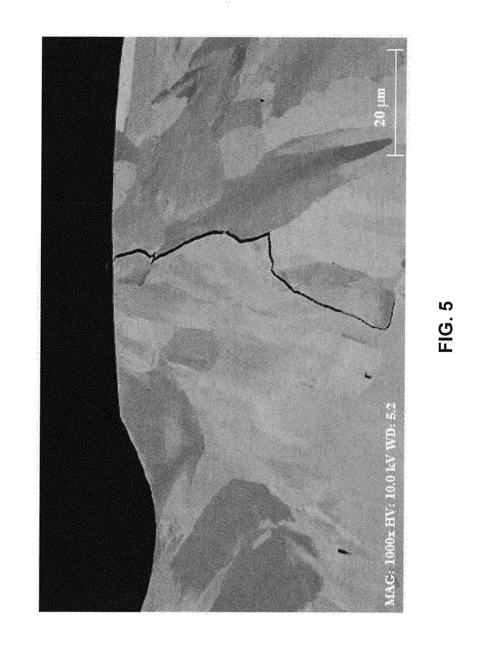
[0084] FIG. 5 is an SEM micrograph of Alloy 2 from Example 1 showing a crack.
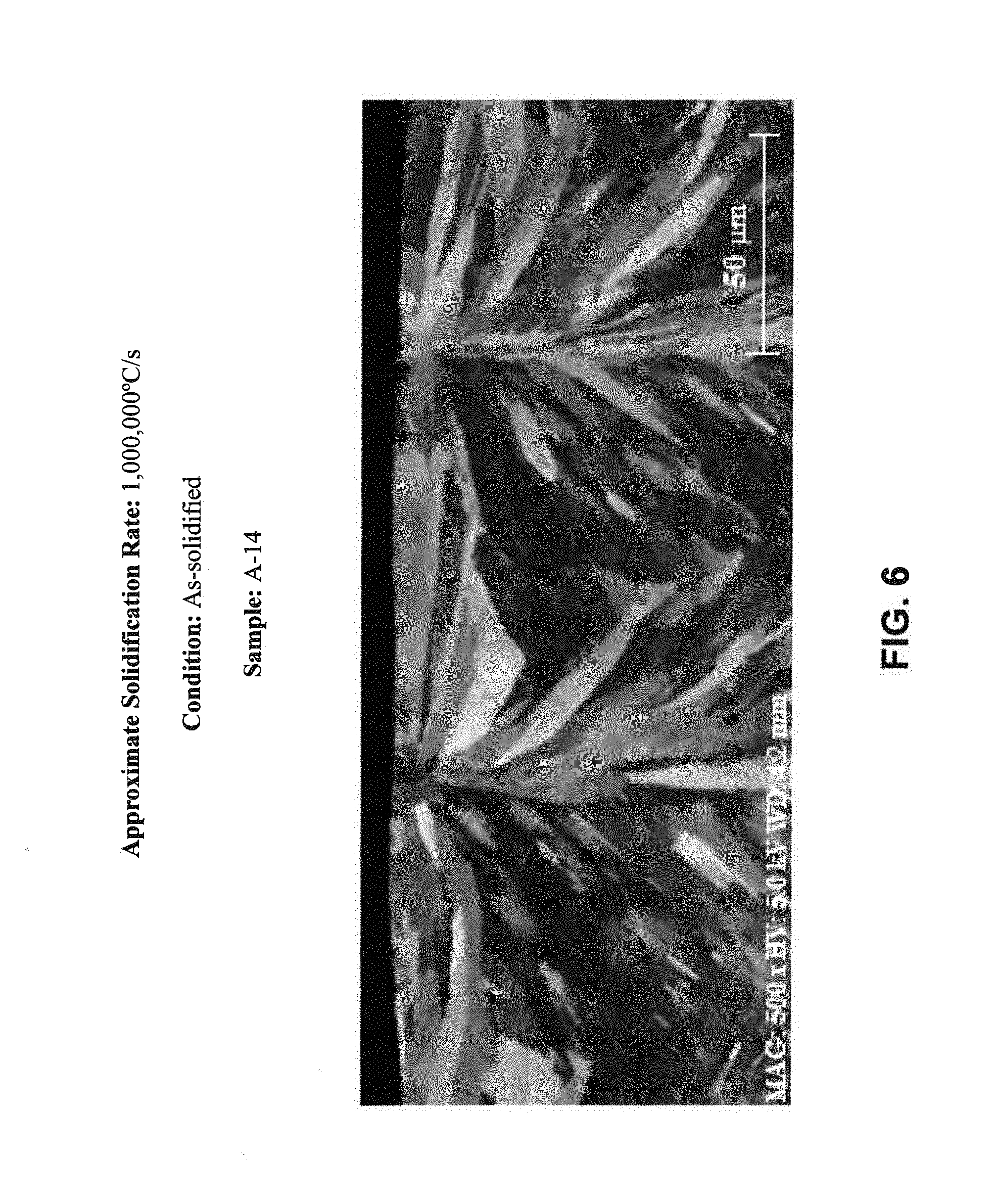
[0085] FIG. 6 is an SEM micrograph at 500.times. magnification of Sample A-14 from Example 2; the microstructure shows a predominantly bcc crystalline structure.
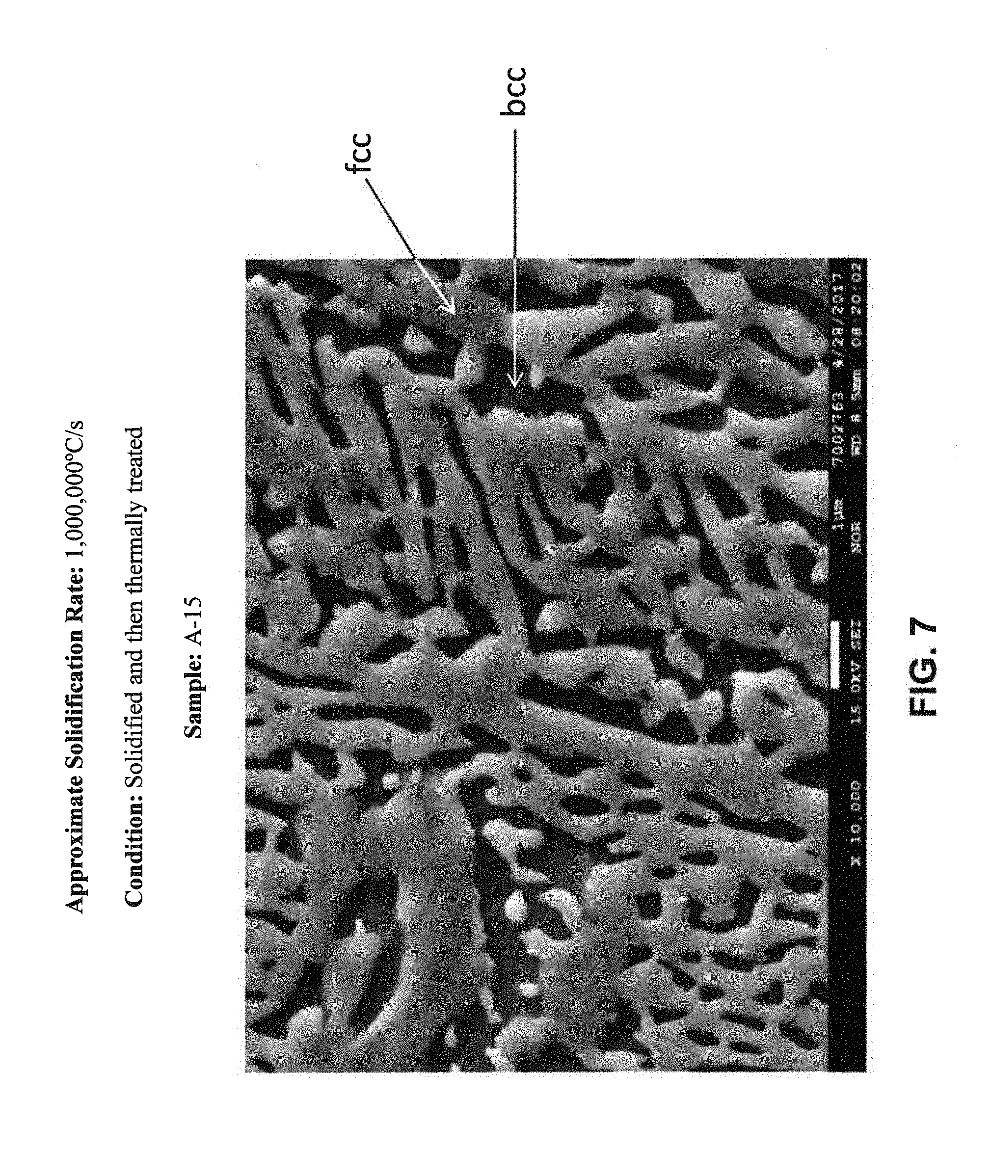
[0086] FIG. 7 is an SEM micrograph at 10,000.times. magnification of Sample A-15 from Example 2; the microstructure shows a mixed fcc+bcc crystalline structure.
[0087] FIG. 8 is an SEM micrograph at 10,000.times. magnification of Sample A-16 from Example 2; the microstructure shows fcc crystalline structures within the bcc crystalline structures.
[0088] FIG. 9a is an SEM micrograph at 500.times. magnification of Sample A-17 from Example 2; the microstructure shows a predominantly bcc crystalline structure.
[0089] FIG. 9b is a portion of FIG. 9a at 8,000.times. magnification; fcc crystalline structures are located along the boundaries of the bcc crystalline structures.
[0090] FIG. 10 is an SEM micrograph at 5,000.times. magnification of Sample A-18 from Example 2; the microstructure shows fcc crystalline structures located along the boundaries of the bcc crystalline structures, and fcc crystalline structures within the bcc crystalline structures, and generally equiaxed crystalline structures (grains).
[0091] FIG. 11 is an SEM micrograph at 5,000.times. magnification of Sample A-19 from Example 2; the microstructure shows fcc crystalline structures located along the boundaries of the bcc crystalline structures, and fcc crystalline structures within the bcc crystalline structures, and generally equiaxed crystalline structures (grains).
[0092] FIG. 12a is an SEM micrograph at 500.times. magnification of Sample A-20 from Example 2; the microstructure shows a mixed fcc+bcc crystalline structure.
[0093] FIG. 12b is a portion of FIG. 12a at 10,000.times. magnification.
[0094] FIG. 13a is an SEM micrograph at 500.times. magnification of Sample A-21 from Example 2; the microstructure shows a mixed fcc+bcc crystalline structure.
[0095] FIG. 13b is a portion of FIG. 13a at 10,000.times. magnification.
[0096] FIG. 14 illustrates the matrix vol. % of fcc crystalline structures versus the solidification rate for as-solidified Alloy A from Example 2.
[0097] FIG. 15 illustrates the matrix vol. % of fcc crystalline structures versus the solidification rate for as-solidified Alloy 6 from Example 1.
DETAILED DESCRIPTION
Examples
Example 1
[0098] Seventeen experimental alloys were produced having the nominal compositions given in Table 1A, below. Furthermore, densities of the alloys measured by Archimedes method are given in Table 1A, below.
TABLE-US-00001 TABLE 1A Nominal Compositions of Example 1 Alloys (in at. %) Alloy Density No. Ni Fe Cr Al Ti Nb B C Hf Zr (g/cm.sup.3) 1 Bal. 32 20 14 1 -- -- -- -- -- 7.3 2 Bal. 32 20 13 1 1 -- -- -- -- 7.4 3 Bal. 30 20 7.5 7.5 -- -- -- -- -- 7.5 4 Bal. 32 20 9 1 3 -- -- -- -- 7.6 5 Bal. 28 18 12 3 1 -- -- -- -- 7.6* 6 Bal. 28 18 12 3 1 0.05 0.2 -- -- 7.6* 7 Bal. 30 20 7.5 7.5 -- 0.05 0.21 -- -- 7.4 8 Bal. 30 20 7.5 7.5 -- 0.05 0.21 0.15 0.06 7.4* 9 Bal. 30 20 14 1 -- -- -- -- -- 7.3 10 Bal. 30 20 11 4 -- -- -- -- -- 7.4 11 Bal. 30 20 6 6 -- -- -- -- -- 7.6 12 Bal. 30 20 9 9 -- -- -- -- -- 7.6 13 Bal. 32 20 13 1 1 0.05 0.21 0.15 0.06 7.3 14 Bal. 32.7 20 14 -- -- -- -- -- -- 7.4* 15 Bal. 32.7 19.9 14 -- -- -- 0.9 -- -- 7.3* 16 Bal. 31.8 19.3 13.6 -- -- -- 4.2 -- -- 7.2* 17 Bal. 29.8 18.1 12.7 -- -- -- 11.8 -- -- 6.8* *Estimated based on alloy of similar composition. **Bal. = the balance of the alloy was nickel.
[0099] Some of the experimental alloys were cast as rectangular ingots (0.5 inch.times.0.5 inch.times.3 inches) for tensile property evaluation. The ingots were cut into cylindrical specimens of 1.5 inches in length and 0.2 inch in diameter using electrical discharge machining. The cylindrical specimens were then lathed into standard testing blanks, each having a larger cylindrical shoulder at each end and a smaller cylindrical gage section in between the shoulders. Some of the testing blanks were heat treated prior to tensile testing as described in Tables 1B and 1C, below.
Room Temperature Tensile Properties
[0100] The room temperature tensile properties (tensile yield strength (TYS), ultimate tensile strength (UTS), elongation, and specific yield strength) of some experimental alloys were evaluated in the as-cast condition, while others were evaluated after thermal processing. The evaluation was performed in the longitudinal direction and in accordance with ASTM E8 (rev. #8M-16A). Results from the evaluation are given in Table 1B, below.
TABLE-US-00002 TABLE 1B Room Temperature Tensile Testing Results Specific Yield Alloy Thermal TYS UTS Elongation Strength No. Treatment (if any) (ksi) (ksi) (%) (ksi*in.sup.3/lbs) 1 Type 1 152 207 13 576 9 Type 2 108 179 13.3 405 10 Type 2 143 188 4.4 533 3 Type 2 173 194 2.2 640 11 Type 2 164 178 2.2 607 1 N/A - As-cast 113 186 20 428 3 N/A - As-cast 128 151 2.2 472 9 N/A - As-cast 92 171 18.9 342 10 N/A - As-cast 97 170 16.7 362 11 N/A - As-cast 120 167 13.3 441
Elevated Temperature Tensile Properties
[0101] The elevated temperature (650.degree. C.) tensile properties of some experimental alloys were evaluated after thermal treatment. The evaluation was performed in the longitudinal direction, and in accordance with ASTM E21-09. Results from the evaluation are given in Table 1C, below.
TABLE-US-00003 TABLE 1C Elevated Temperature (650.degree. C.) Tensile Testing Results Specific Yield Alloy Thermal TYS UTS Elongation Strength No. Treatment (ksi) (ksi) (%) (ksi*in.sup.3/lbs) 2 Type 1 106 138 36 396 3 Type 2 140 169 20 517 4 Type 1 122 161 25 444 5 Type 2 130 164 25 473 9 Type 2 69 99 31 260 10 Type 2 105 137 30 393
Solidification Rate Evaluations
[0102] The experimental alloys were solidified by two methods that realize solidification rates on the order of 1,000,000.degree. C./s and 10,000-100,000.degree. C./s. Following solidification, the tendency for the material to crack at the employed solidification rate was evaluated in the as-solidified condition. The tendency for the material to crack was evaluated by (1) visual inspection (e.g., with the human eye) and/or (2) micrograph inspection. In this regard, the experimental alloys were evaluated on a qualitative pass/fail rating, where a pass rating indicates the as-solidified material was free of cracks and a fail rating indicates the material contained at least one crack. The as-solidified materials were first analyzed by visual inspection. If it was apparent from visual inspection that the solidified material contained cracks, the alloy was given a rating of "fail". If the material appeared to have no cracks by visual inspection, appropriate micrographs were taken and analyzed to make the determination. Results from the solidification evaluations are given in Table 1D, below. An example micrograph of Alloy 2, having been solidified at approximately at 1,000,000.degree. C./s is given in FIG. 5. As illustrated in FIG. 5, a crack near the surface of the material can be seen at 1,000.times. magnification. An example micrograph of Alloy 1 having been solidified at approximately 10,000.degree. C./s is given in FIG. 10. As illustrated in FIG. 10, the material is free of cracks.
TABLE-US-00004 TABLE 1D Solidification Experiment Cracking Evaluation Results Alloy Solidification No. 1,000,000.degree. C./s 10,000-100,000.degree. C./s Pathway 1 Fail Pass near-eutectic* 2 Fail Fail near eutectic* 3 Pass Pass fcc-first 4 Pass Pass fcc-first 5 Pass Pass fcc-first 6 Pass Pass fcc-first 7 Pass Pass fcc-first 8 Pass Pass fcc-first 9 Pass Pass fcc-first 10 Pass Pass fcc-first 11 Pass Pass fcc-first 12 Pass Pass fcc-first 13 Fail Fail near eutectic* 14 N/A N/A N/A 15 Pass Pass fcc-first 16 Pass Pass bcc-first 17 Fail Fail bcc-first *Near-eutectic solidification pathway reflects a solidification pathway where fcc and bcc generally form concomitantly (i.e., neither an fcc-first or bcc-first solidification pathway).
Example 2
Tensile Properties Evaluation
[0103] Three additional experimental alloys were cast as ingots (0.5 inch.times.0.5 inch.times.3 inch). The nominal compositions of the three additional experimental alloys are given in Table 2A, below. Alloy A has the same nominal composition as Alloy 1 of Example 1, above. Alloy B is a prior art alloy from Dong, Y., Gao, X., Lu, Y., Wang, I., & Li, T. (2016). "A multi-component AlCrFe2Ni2 alloy with excellent mechanical properties". Materials Letters, 169, 62-64., and Alloy C is a prior art alloy from Dong, Y., Lu, Y., Kong, J., Zhang, J., & Li, T. (2013). "Microstructure and mechanical properties of multi-component AlCrFeNiMox high-entropy alloys". Journal of Alloys and Compounds, 573, 96-101.
TABLE-US-00005 TABLE 2A Nominal Compositions of Experimental Alloys A, B, and C Alloy No. Ni Fe Cr Al Ti A 33 32 20 14 1 (Inv.) B 33.3 33.3 16.7 16.7 Trace (Prior Art) C 25 25 25 25 Trace (Prior Art)
[0104] Following casting, some ingots of Alloy A and B were cut in the longitudinal direction into rectangular samples (0.25 inch.times.0.5 inch.times.3 inches) in preparation for rolling. The samples were heated to 900.degree. C. and hot rolled, in six passes, to a net relative reduction of approximately 55%. The wrought samples were examined for edge cracking. Alloy A appeared to be free of cracks, while Alloy B exhibited severe edge cracking. Alloy A was therefore in a condition for further testing, described below.
Wrought Samples
[0105] Four specimens (A-1 through A-4) from the Alloy A ingots were thermally treated, after which, room temperature tensile properties were measured in the longitudinal direction and in accordance with ASTM E8 (rev. #8M-16A). The results from the evaluation are given in Table 2B, below.
TABLE-US-00006 TABLE 2B Wrought Room Temperature Tensile Properties of Alloy A Sample Thermal TYS UTS Elong. No. Treatment (ksi) (ksi) (%) A-1 Practice #1 124 169 17 A-2 Practice #2 161 196 10 A-3 Practice #3 142 182 8 A-4 Practice #4 108 158 21
Non-Wrought Samples
[0106] Four specimens (A-5 through A-8) from the Alloy A ingots and four specimens (C-1 through C-4) from the Alloy C ingots were thermally treated, after which room temperature tensile properties of heat treated samples were measured in accordance with ASTM E8 (rev. #8M-16A). Samples of Alloy C were thermally treated in an argon atmosphere to prevent oxidation. As illustrated in Table 2C, the samples of Alloy C failed before yielding. Thus, only the ultimate tensile strength was measured for the Alloy C samples, and no further samples were evaluated due to the poor ductility.
TABLE-US-00007 TABLE 2C As-Cast Room Temperature Tensile Properties of Alloy A and C Sample Thermal TYS UTS Elong. No. Treatment (ksi) (ksi) (%) A-5 Condition #1 69 153 28 A-6 Condition #2 96 154 12 A-7 Condition #3 116 179 11 A-8 Condition #4 156 212 14 C-1 Condition #5 -- 116 0.0 C-2 Condition #5 -- 100 0.0 C-3 Condition #5 -- 85 0.0 C-4 Condition #5 -- 103 0.0
[0107] Four additional specimens (A-8 through A-13) from the Alloy A ingots were prepared for tensile testing in the as-cast condition (i.e., without thermal treatment). Sample A-9 was evaluated at room temperature in the longitudinal direction and in accordance with ASTM E8 (rev. #8M-16A). Samples A-10 through A-13 were evaluated in the longitudinal direction at 500.degree. C., 600.degree. C., 650.degree. C., and 700.degree. C., and in accordance with ASTM E21-09. Results from the evaluations are given in Table 2D, below.
TABLE-US-00008 TABLE 2D Tensile Testing Results for As-Cast Alloy A at Various Temperatures Sample Temperature TYS UTS Elong. No. (.degree. C.) (ksi) (ksi) (%) A-9 25 113 176 13 A-10 500 97 144 39 A-11 600 90 116 47 A-12 650 77 105 26 A-13 700 58 81 28
Solidification Rate Evaluations
[0108] As noted above, Alloy A was selected for a separate set of solidification rate evaluations. Samples of Alloy A were solidified at rates varying from about 10.degree. C./s to about 1,000,000.degree. C./s. Following solidification, and in some cases post-solidification thermal treatment, the samples were microstructurally characterized. Furthermore, hardness, room temperature tensile properties, and elevated temperature tensile properties (e.g., 450.degree. C. and 650.degree. C.) of the samples were evaluated. The samples conditions (e.g., as-solidified; thermally treated) are given in Table 2E, below.
Microstructural Characterization
[0109] Alloy A was subjected to solidification rates varying from about 10.degree. C./s to about 1,000,000.degree. C./s. Following solidification, and in some cases following post-solidification thermal treatment, appropriate micrographs were taken of the solidified materials. The solidification rate and conditions (e.g., thermal history or as-solidified) are given in Table 2E, below. Additionally, figure numbers of the micrographs are illustrated in FIGS. 6-13b, are given in Table 2E.
TABLE-US-00009 TABLE 2E Solidification Evaluation Sample Approximate Corresponding No. Solidification Rate Condition FIG(S). A-14 1,000,000.degree. C./s As-solidified FIG. 6 A-15 1,000,000.degree. C./s Solidified and then FIG. 7 thermally treated A-16 1,000,000.degree. C./s Solidified and then FIG. 8 thermally treated A-17 10,000.degree. C./s As-solidified FIGS. 9a to 1,000,000.degree. C./s and 9b A-18 10,000.degree. C./s As-solidified FIG. 10 A-19 1,000.degree. C./s As-solidified FIG. 11 A-20 100.degree. C./s Solidified and then FIGS. 12a thermally treated and 12b A-21 10.degree. C./s-100.degree. C./s As-solidified FIGS. 13a and 13b
[0110] The microstructures shown in FIGS. 6-13b were characterized using Electron Backscatter Diffraction ("EBSD") to determine the volumetric percentage of matrix fcc and matrix bcc crystalline structures (i.e., phases other than fcc/bcc were not measured or characterized). Elemental compositions within the fcc and bcc crystalline structures were determined using Energy Dispersive X-Ray Spectroscopy ("EDS"). Results from the evaluations are given in Table 2F, below. The micrographs given in FIGS. 6-13b (listed above in Table 2E) were used for the microstructural characterization.
TABLE-US-00010 TABLE 2F Microstructural Analysis of fcc and bcc Crystalline Structures Elemental Composition Sample Matrix Vol. within Phase (at. %) No. Phase % of phase Al Cr Fe Ni Ti A-14 fcc 0 -- -- -- -- -- bcc 100 13.1 20.3 35.1 30.3 1.2 A-15 fcc 73 6.5 23.4 37.3 31.9 0.9 bcc 27 19.8 11.3 21.0 46.0 1.9 A-16 fcc 1 9.7 20.1 34.9 34.4 0.9 bcc 99 10.1 20.7 34.2 33.9 1.1 A-17 fcc 0 -- -- -- -- -- bcc 100 12.2 19.3 35.4 32.2 0.9 A-18 fcc 9 11.7 18.3 31.2 37.7 1.1 bcc 91 9.8 21.4 34.3 33.4 1.1 A-19 fcc 46 9.9 20.4 34.2 34.4 1.1 bcc 54 9.9 20.4 34.2 34.4 1.1 A-20 fcc Not 7.7 21.37 35.6 34.5 0.9 Measured bcc Not 11.4 21.3 32.1 34.1 1.1 Measured A-21 fcc 56 9.7 22.1 37.5 30.0 0.7 bcc 44 15.3 24.1 32.1 27.7 0.8
[0111] As illustrated in Table 2F, solidification rates on the order of 10,000 to 1,000,000.degree. C./s realized low amounts (e.g., less than 5 vol. %) of the fcc phase in the as-solidified condition. A solidification rate on the order of 10,000.degree. C./s realized a slight increase in the amount of fcc phase in the as-solidified condition at 8.55 vol. %. However, at a solidification rate of approximately 1,000.degree. C., a large increase in the amount of fcc phase was realized in the as-solidified condition. These results are further illustrated in FIG. 14. Alloy A solidifies by a near-eutectic solidification pathway.
[0112] Alloy 6 from Example 1 was also evaluated, the results of which are given in Table 2G and FIG. 15. As illustrated, Alloy 6 realizes a microstructure having fcc as the predominant matrix phase over the solidification range of from 10-1,000,000.degree. C./s. Thus, Alloy 6 realizes an fcc-first solidification pathway.
TABLE-US-00011 TABLE 2G Vol. % of Matrix fcc and bcc versus Solidification Rate for Example 1 Alloy 6 Approximate Solidification Rate Matrix Vol. % fcc 1000000.degree. C./s 99 10,000-100,000.degree. C./s 87 10.degree. C./s 83
Hardness Evaluation
[0113] Specimens A-14 through A-21 were also subjected to hardness testing in accordance with ASTM E92. Results for the evaluations (given in Vickers Pyramid Numbers (HV)) are given in Table 2H, below. Values are an average of multiple specimens and corresponding uncertainties reflect a normally distributed, 95% confidence interval (i.e., 2-sigma).
TABLE-US-00012 TABLE 2H Hardness Evaluation Results Sample No. Hardness A-14 643 .+-. 42 A-15 286 .+-. 54 A-16 616 .+-. 80 A-17 630 .+-. 40 A-18 544 .+-. 30 A-19 389 .+-. 16 A-20 -- A-21 336 .+-. 21
Tensile Properties Evaluation
[0114] Room temperature and elevated temperature tensile properties of samples A-18 through A-21 were tested, the results of which are given in Table 21, below. The sample conditions for the tensile property evaluations correspond to the conditions described in Table 2E. Room temperature tensile properties were evaluated in accordance with ASTM E8 (rev. #8M-16A) and elevated temperature tensile properties were evaluated in accordance with ASTM E21-09.
TABLE-US-00013 TABLE 2I Room Temperature and Elevated Temperature Tensile Properties Room Temp. 450.degree. C. 650.degree. C. Sample TYS UTS Elong. TYS UTS Elong. TYS UTS Elong. No. (ksi) (ksi) (%) (ksi) (ksi) (%) (ksi) (ksi) (%) A-18 183 240 3 144 205 49 52 101 67 A-19 142 205 16 -- -- -- -- -- -- A-20 158 218 7 122 165 11 75 114 18 A-21 113 186 20 97 144 39 77 105 26
[0115] While various embodiments of the new technology described herein have been described in detail, it is apparent that modifications and adaptations of those embodiments will occur to those skilled in the art. However, it is to be expressly understood that such modifications and adaptations are within the spirit and scope of the presently disclosed technology.
* * * * *
D00001
D00002
D00003
D00004
D00005
D00006
D00007
D00008
D00009
D00010
D00011
D00012
D00013

D00014

D00015

XML
uspto.report is an independent third-party trademark research tool that is not affiliated, endorsed, or sponsored by the United States Patent and Trademark Office (USPTO) or any other governmental organization. The information provided by uspto.report is based on publicly available data at the time of writing and is intended for informational purposes only.
While we strive to provide accurate and up-to-date information, we do not guarantee the accuracy, completeness, reliability, or suitability of the information displayed on this site. The use of this site is at your own risk. Any reliance you place on such information is therefore strictly at your own risk.
All official trademark data, including owner information, should be verified by visiting the official USPTO website at www.uspto.gov. This site is not intended to replace professional legal advice and should not be used as a substitute for consulting with a legal professional who is knowledgeable about trademark law.