Paper Sheet Deposit Machine And A Paper Sheet Storage Equipment Thereof
YANG; Wen-Fu ; et al.
U.S. patent application number 15/826368 was filed with the patent office on 2019-01-24 for paper sheet deposit machine and a paper sheet storage equipment thereof. The applicant listed for this patent is Masterwork Automodules Tech Corp. Ltd.. Invention is credited to Wen-Hsien TSAI, Wen-Fu YANG.
| Application Number | 20190023433 15/826368 |
| Document ID | / |
| Family ID | 60673490 |
| Filed Date | 2019-01-24 |


View All Diagrams
| United States Patent Application | 20190023433 |
| Kind Code | A1 |
| YANG; Wen-Fu ; et al. | January 24, 2019 |
PAPER SHEET DEPOSIT MACHINE AND A PAPER SHEET STORAGE EQUIPMENT THEREOF
Abstract
A paper sheet storage equipment includes an inner housing defining an opening, a bag installation unit, a temporary storage unit including a limiting member and a supporting plate which defines a temporary storage region communicated with the opening, and a sealing unit for sealing the paper sheet storage bag. Multiple paper sheets are conveyed one at a time and through the opening into the inner housing to be stacked on the supporting plate. The limiting member is operable to engage the supporting plate such that the supporting plate supports the paper sheets, and is operable to disengage the supporting plate such that the supporting plate is swingable to allow the paper sheets to drop into the paper sheet storage bag.
| Inventors: | YANG; Wen-Fu; (Taipei City, TW) ; TSAI; Wen-Hsien; (Taipei City, TW) | ||||||||||
| Applicant: |
|
||||||||||
|---|---|---|---|---|---|---|---|---|---|---|---|
| Family ID: | 60673490 | ||||||||||
| Appl. No.: | 15/826368 | ||||||||||
| Filed: | November 29, 2017 |
| Current U.S. Class: | 1/1 |
| Current CPC Class: | G07D 11/14 20190101; B65B 35/50 20130101; G07D 11/23 20190101; G07D 11/13 20190101; B65B 5/101 20130101; B65B 25/14 20130101; B65B 57/14 20130101; B65H 31/10 20130101; B65B 7/02 20130101; B65H 31/00 20130101; G07D 11/22 20190101; B65B 5/108 20130101; B65B 51/146 20130101; G07D 11/12 20190101; B65B 35/24 20130101; G07D 11/20 20190101; G07D 11/16 20190101; B65H 31/3018 20130101; G07D 2211/00 20130101; B65H 29/46 20130101; B65H 2301/422548 20130101; B65B 5/067 20130101; B65B 5/08 20130101; B65B 35/243 20130101; B65H 2701/1912 20130101 |
| International Class: | B65B 25/14 20060101 B65B025/14; B65H 31/00 20060101 B65H031/00; B65B 5/06 20060101 B65B005/06; B65B 5/08 20060101 B65B005/08; B65B 7/02 20060101 B65B007/02; B65B 35/50 20060101 B65B035/50; B65B 35/24 20060101 B65B035/24 |
Foreign Application Data
| Date | Code | Application Number |
|---|---|---|
| Jul 19, 2017 | TW | 106124174 |
Claims
1. A paper sheet storage equipment adapted for storing a plurality of paper sheets in a paper sheet storage bag, said paper sheet storage equipment comprising: an inner housing defining an opening; a bag installation unit disposed inside said inner housing and adapted for the paper sheet storage bag to be installed thereon; a temporary storage unit disposed inside said inner housing, and including a supporting plate and a limiting member, said supporting plate defining a temporary storage region that is spatially communicated with said opening; and a sealing unit disposed nearby said bag installation unit and adapted to seal a bag opening of the paper sheet storage bag, wherein the paper sheets are conveyed one at a time and through said opening into said inner housing to be temporarily stacked on said supporting plate of said temporary storage unit, and said limiting member of said temporary storage unit is operable to engage said supporting plate such that said supporting plate is adapted to support the paper sheets; and wherein said limiting member is operable to disengage said supporting plate such that said supporting plate is swingable to allow the paper sheets stacked thereon to drop into the paper sheet storage bag.
2. The paper sheet storage equipment as claimed in claim 1, wherein: said temporary storage unit further includes a seat to which said limiting member is movably connected; two of said supporting plates that are horizontally spaced apart from each other, each of said supporting plates being pivotably connected to said seat; and two torsion springs that are connected to said seat, each of said torsion springs having two ends that respectively abut against said seat and a respective one of said supporting plates for biasing a corresponding one of said supporting plates to a horizontal position; when said limiting member engages said supporting plates, said supporting plates are horizontal and cooperate to support the paper sheets; when said limiting member disengages said supporting plates, each of said supporting plates is swingable downwardly, so that the paper sheets drop into the paper sheet storage bag; and after the paper sheets separate from said supporting plates, said torsion springs bias and return each of said supporting plates to the horizontal position.
3. The paper sheet storage equipment as claimed in claim 2, wherein: each of said supporting plates has a protrusion, said limiting member having two spaced apart horizontal slots each having an open end, said horizontal slots being opened in the same direction; and said limiting member is operable to move between an engaging position, where said horizontal slots of said limiting member respectively engage said protrusions of said supporting plates, and a disengaging position, where said horizontal slots of said limiting member are disengaged from said protrusions of said supporting plates.
4. The paper sheet storage equipment as claimed in claim 2, wherein: each of said supporting plates is formed with a pin hole, said limiting member having two spaced apart pins; and said limiting member is operable to move between an engaging position, where said pins of said limiting member are respectively inserted into said pin holes of said supporting plates to hold each of said supporting plates at the horizontal position, and a disengaging position, where said pins of said limiting member are respectively disengaged from said pin holes of said supporting plates.
5. The paper sheet storage equipment as claimed in claim 2, wherein: said limiting member has two spaced apart protrusions; and said limiting member is operable to move between an engaging position, where said protrusions of said limiting member are respectively underneath said supporting plates for blocking each of said supporting plates from downward pivotal movement from the horizontal position, and a disengaging position, where said limiting member is horizontally spaced apart from said supporting plates to allow said supporting plates to pivot downwardly.
6. The paper sheet storage equipment as claimed in claim 2, wherein said temporary storage unit further includes an extendable member connected between said inner housing and said seat, and being operable to vertically move said seat, said limiting member, said supporting plates and said torsion springs above or in the paper sheet storage bag.
7. The paper sheet storage equipment as claimed in claim 6, wherein said extendable member has a deployable scissor structure.
8. The paper sheet storage equipment as claimed in claim 6, wherein said temporary storage unit further includes a roller, and a film being rolled on said roller and having an end connected to said seat.
9. The paper sheet storage equipment as claimed in claim 8, further comprising a lower conveying unit connected to the temporary storage unit, said lower conveying unit including a wheel unit, said wheel unit including a plurality of friction wheel sets and a deformation wheel set, each of said friction wheel sets including a driving wheel and a driven wheel, said deformation wheel set including two spaced apart first wheels and a second wheel disposed between said first wheels and having a diameter larger than that of each of said first wheels, wherein, when each of the paper sheets is passing through said lower conveying unit, said second wheel deforms the each of the paper sheets.
10. The paper sheet storage equipment as claimed in claim 9, further comprising an extendable unit disposed above said supporting plate, and a sensor disposed on said extendable unit, said sensor being configured to sense the amount of the paper sheets stacked on said supporting plate, said extendable unit being operable to move to abut against the paper sheets stacked on said supporting plate.
11. A paper sheet deposit machine adapted for storing a plurality of paper sheets in a paper sheet storage bag, said paper sheet deposit machine comprising: a housing; a paper sheet handling module disposed inside said housing, said paper sheet handling module including an inlet, an outlet, an opening, a discrimination unit, and an upper conveying path that connects said inlet, said discrimination unit, said outlet and said opening; a bag installation unit disposed inside said housing and adapted for the paper sheet storage bag to be installed thereon; a temporary storage unit disposed inside said housing, and including a supporting plate and a limiting member, said supporting plate defining a temporary storage region that is spatially communicated with said opening; and a sealing unit disposed nearby said bag installation unit and adapted to seal a bag opening of the paper sheet storage bag, wherein said inlet is adapted for receiving the paper sheets, said upper conveying path conveys the paper sheets one at a time from said inlet to pass through said discrimination unit, where said discrimination unit discriminates the paper sheets, said upper conveying path conveys the paper sheets un-allowed by said discrimination unit to said outlet, said upper conveying path conveys the paper sheets allowed by said discrimination unit to be temporarily stacked on said supporting plate, and said limiting member of said temporary storage unit is operable to engage said supporting plate such that said supporting plate is adapted to support the paper sheets allowed by said discrimination unit; and wherein said limiting member is operable to disengage said supporting plate such that said supporting plate is swingable to allow the paper sheets stacked thereon to drop into the paper sheet storage bag.
12. The paper sheet deposit machine as claimed in claim 11, wherein: said temporary storage unit further includes a seat to which said limiting member is movably connected; two of said supporting plates that are horizontally spaced apart from each other, each of said supporting plates being pivotably connected to said seat; and two torsion springs that are connected to said seat, each of said torsion springs having two ends that respectively abut against said seat and a respective one of said supporting plates for biasing a corresponding one of said supporting plates to a horizontal position; when said limiting member engages said supporting plates, said supporting plates are horizontal and cooperate to support the paper sheets; when said limiting member disengages said supporting plates, each of said supporting plates is swingable downwardly, so that the paper sheets drop into the paper sheet storage bag; and after the paper sheets separate from said supporting plates, said torsion springs bias and return each of said supporting plates to the horizontal position.
13. The paper sheet deposit machine as claimed in claim 12, wherein: each of said supporting plates has a protrusion, said limiting member having two spaced apart horizontal slots each having an open end, said horizontal slots being opened in the same direction; and said limiting member is operable to move between an engaging position, where said horizontal slots of said limiting member respectively engage said protrusions of said supporting plates, and a disengaging position, where said horizontal slots of said limiting member are disengaged from said protrusions of said supporting plates.
14. The paper sheet deposit machine as claimed in claim 12, wherein: each of said supporting plates is formed with a pin hole, said limiting member having two spaced apart pins; and said limiting member is operable to move between an engaging position, where said pins of said limiting member are respectively inserted into said pin holes of said supporting plates to hold each of said supporting plates at the horizontal position, and a disengaging position, where said pins of said limiting member are respectively disengaged from said pin holes of said supporting plates.
15. The paper sheet deposit machine as claimed in claim 12, wherein: said limiting member has two spaced apart protrusions; and said limiting member is operable to move between an engaging position, where said protrusions of said limiting member are respectively underneath said supporting plates for blocking each of said supporting plates from downward pivotal movement from the horizontal position, and a disengaging position, where said limiting member is horizontally spaced apart from said supporting plates to allow said supporting plates to pivot downwardly.
16. The paper sheet deposit machine as claimed in claim 12, wherein said temporary storage unit further includes an extendable member connected between said housing and said seat, and being operable to vertically move said seat, said limiting member, said supporting plates and said torsion springs above or in the paper sheet storage bag.
17. The paper sheet deposit machine as claimed in claim 16, wherein said extendable member has a deployable scissor structure.
18. The paper sheet deposit machine as claimed in claim 16, wherein said temporary storage unit further includes a roller, and a film being rolled on said roller and having an end connected to said seat.
Description
CROSS-REFERENCE TO RELATED APPLICATION
[0001] This application claims priority of Taiwanese Patent Application No. 106124174, filed on Jul. 19, 2017.
FIELD
[0002] The disclosure relates to a paper sheet deposit machine that is adapted for storing a plurality of paper sheets in a paper sheet storage bag, and to a paper sheet storage equipment of the paper sheet deposit machine.
BACKGROUND
[0003] Banknotes are widely used in people's daily life. The handling and storage of banknotes in the banking business are especially important. Equipments have been developed for facilitating handling of banknotes by the tellers, and enhancing security of banknotes storage.
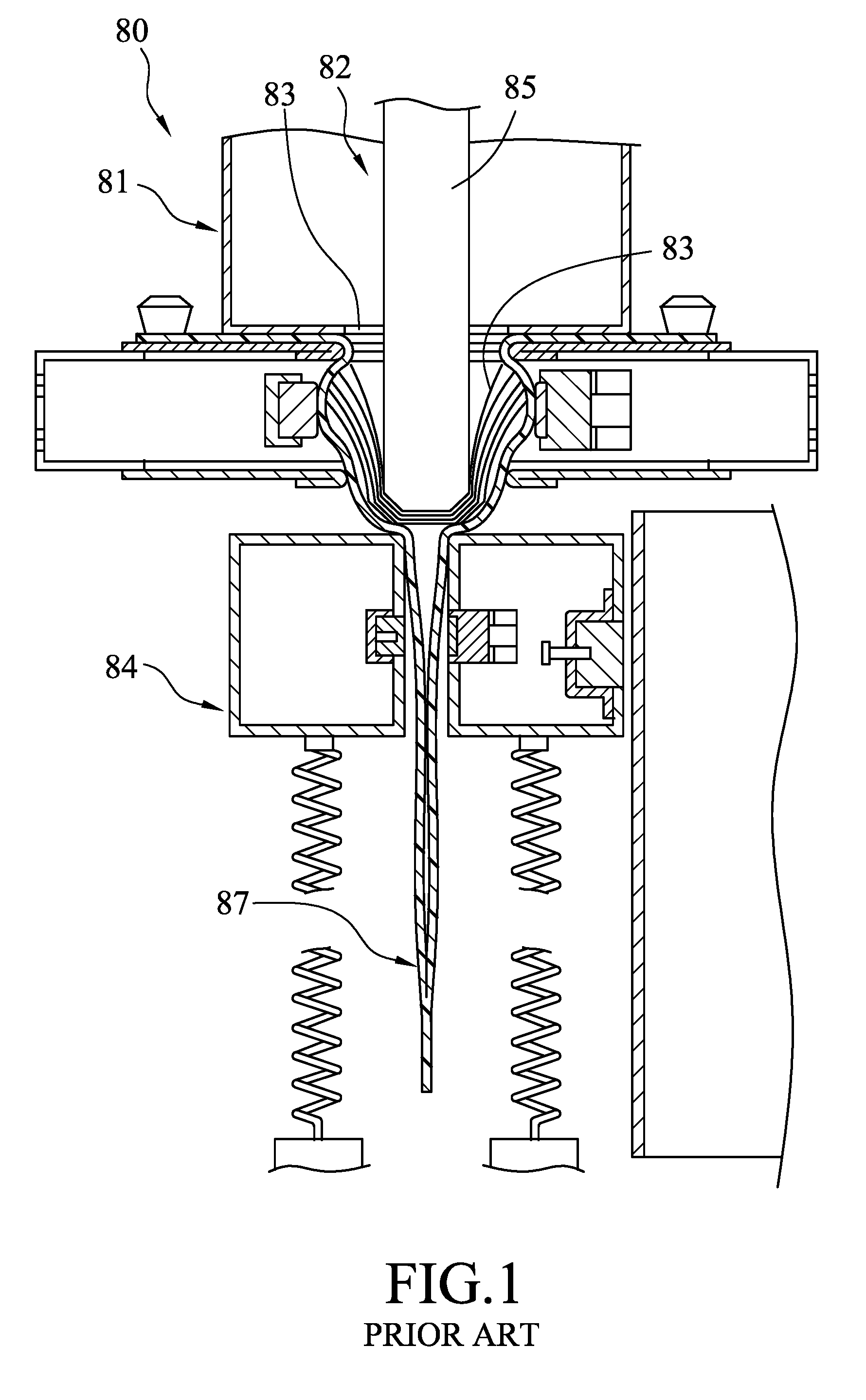
[0004] FIG. 1 shows a banknote storage equipment 80 disclosed by U.S. Patent Application Publication 2016/0031574A1 that includes a container 81 defining an inner space 82 and formed with an opening 83, and a support 84 disposed below the opening 83 of the container 81. The banknote storage equipment 80 is provided with a piston 85 movably disposed within the inner space 82 and aligned with the opening 83. A plurality of banknotes 86 are disposed in the inner space 82 of the container 81, followed by being pushed by the piston 85 to pass through the opening 83 and to be disposed on the support 84 and received in a bag 87.
[0005] It is desirable in the art to develop an equipment that further improves handling and storage of banknotes.
SUMMARY
[0006] According to an aspect of this disclosure, a paper sheet storage equipment is adapted for storing a plurality of paper sheets in a paper sheet storage bag. The paper sheet storage equipment includes an inner housing, a bag installation unit, a temporary storage unit and a sealing unit.
[0007] The inner housing defines an opening. The bag installation unit is disposed inside the inner housing, and is adapted for the paper sheet storage bag to be installed thereon. The temporary storage unit is disposed inside the inner housing, and includes a supporting plate and a limiting member. The supporting plate defines a temporary storage region that is spatially communicated with the opening. The sealing unit is disposed nearby the bag installation unit, and is adapted to seal a bag opening of the paper sheet storage bag. The paper sheets are conveyed one at a time and through the opening into the inner housing to be temporarily stacked on the supporting plate of the temporary storage unit. The limiting member of the temporary storage unit is operable to engage the supporting plate such that the supporting plate is adapted to support the paper sheets. The limiting member is operable to disengage the supporting plate such that the supporting plate is swingable to allow the paper sheets stacked thereon to drop into the paper sheet storage bag.
[0008] According to another aspect of this disclosure, a paper sheet deposit machine is adapted for storing a plurality of paper sheets in a paper sheet storage bag. The paper sheet deposit machine includes a housing, a paper sheet handling module, a bag installation unit, a temporary storage unit and a sealing unit.
[0009] The paper sheet handling module includes an inlet, an outlet, an opening, a discrimination unit, and an upper conveying path that connects the inlet, the discrimination unit, the outlet and the opening. The bag installation unit is disposed inside the housing and is adapted for the paper sheet storage bag to be installed thereon. The temporary storage unit is disposed inside the housing, and includes a supporting plate and a limiting member. The supporting plate defining a temporary storage region that is spatially communicated with the opening. The sealing unit is disposed nearby the bag installation unit and is adapted to seal a bag opening of the paper sheet storage bag. The inlet receives the paper sheets into the housing. The upper conveying path conveys the paper sheets one at a time from the inlet to pass through the discrimination unit, where the discrimination unit discriminates the paper sheets. The upper conveying path conveys the paper sheets un-allowed by the discrimination unit to the outlet. The upper conveying path conveys the paper sheets allowed by the discrimination unit to be temporarily stacked on the supporting plate. The limiting member of the temporary storage unit is operable to engage the supporting plate such that the supporting plate is adapted to support the paper sheets allowed by the discrimination unit. The limiting member is operable to disengage the supporting plate such that the supporting plate is swingable to allow the paper sheets stacked thereon to drop into the paper sheet storage bag.
BRIEF DESCRIPTION OF THE DRAWINGS
[0010] Other features and advantages of the present disclosure will become apparent in the following detailed description of the embodiment with reference to the accompanying drawings, of which:
[0011] FIG. 1 is a schematic view of a banknote storage equipment of US Patent Application Publication 2016/0031574 A1;
[0012] FIG. 2 is a fragmentary schematic sectional view of an embodiment of a paper sheet deposit machine according to the present disclosure, where a housing and a paper sheet handling module of the embodiment are schematically shown;
[0013] FIG. 3 is a perspective view of a paper sheet storage equipment of the embodiment;
[0014] FIG. 4 is a sectional view of the embodiment, where the paper sheet handling module of the embodiment is omitted;
[0015] FIG. 5 is a sectional view of a lower conveying unit of the paper sheet storage equipment of the embodiment;
[0016] FIG. 6 is a schematic view of the lower conveying unit;
[0017] FIG. 7 is a schematic view of the lower conveying unit, showing a paper sheet being deformed by a deformation wheel set of the lower conveying unit;
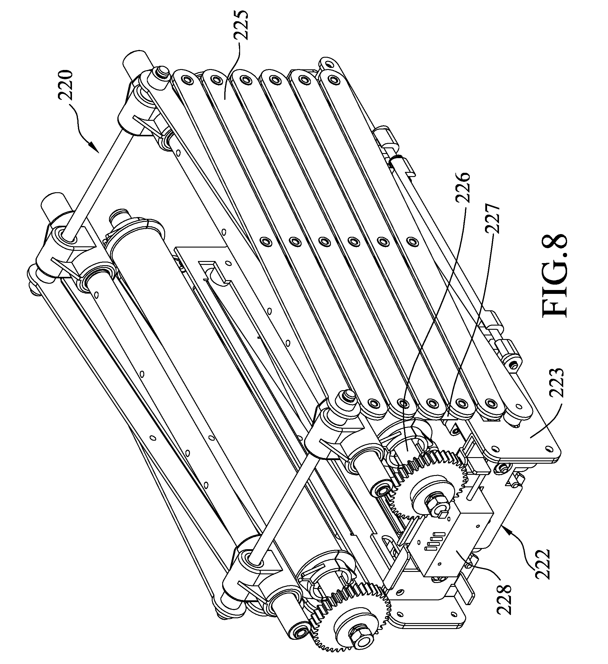
[0018] FIG. 8 is a perspective view of a temporary storage unit of the embodiment;
[0019] FIG. 9 is a perspective view showing two supporting plates of the temporary storage unit at a horizontal position;
[0020] FIG. 10 is a schematic side view showing a limiting member of this embodiment being movable between an engaging position and a disengaging position, and the supporting plates of the temporary storage unit being swingable downwardly when the limiting member is at the disengaging position;
[0021] FIG. 11 is a schematic perspective view showing a variation of the embodiment;
[0022] FIG. 12 is a schematic perspective view showing another variation of the embodiment;
[0023] FIG. 13 is a schematic sectional view of the temporary storage unit, showing a temporary storage region defined by the supporting plates; and
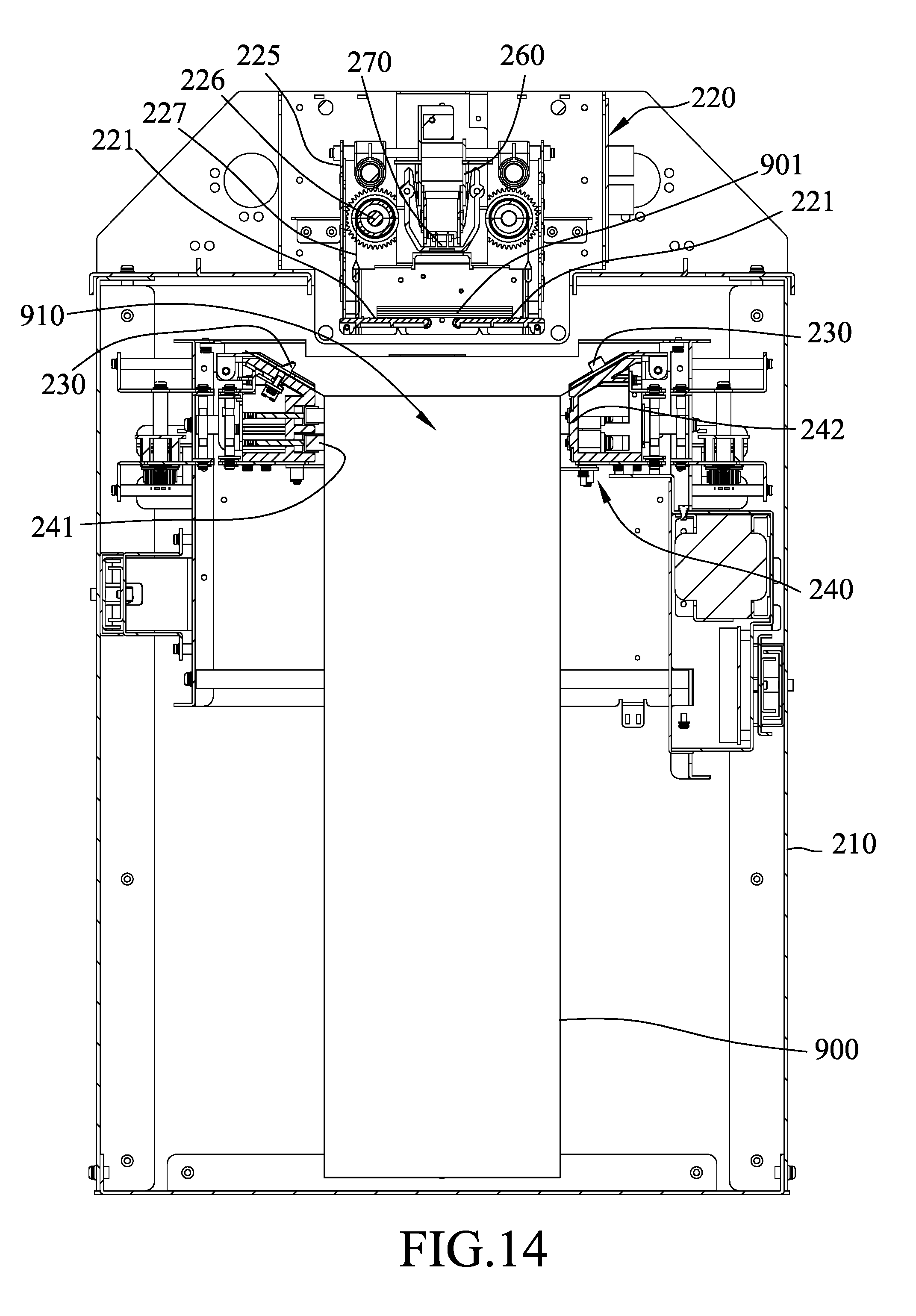
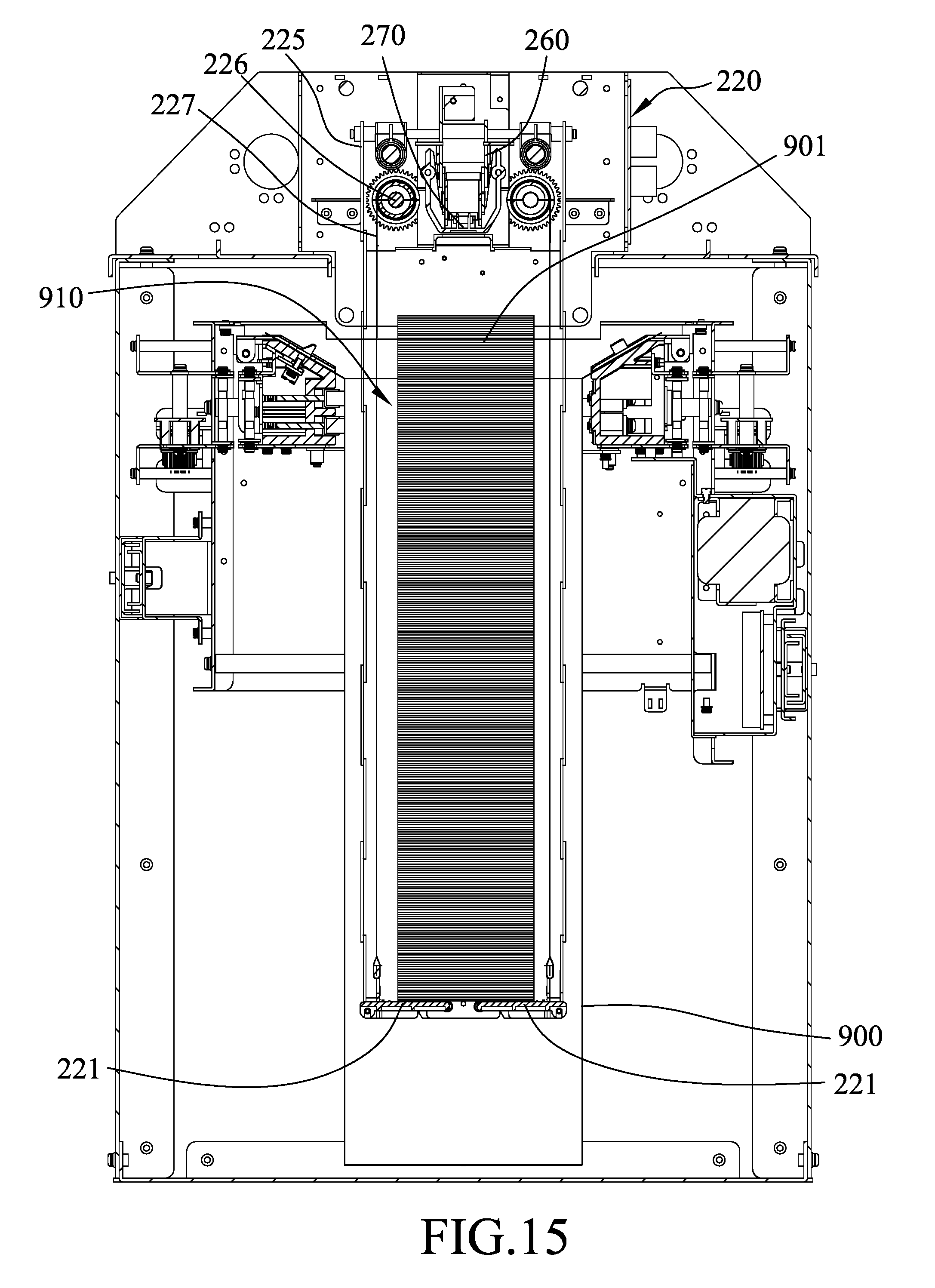
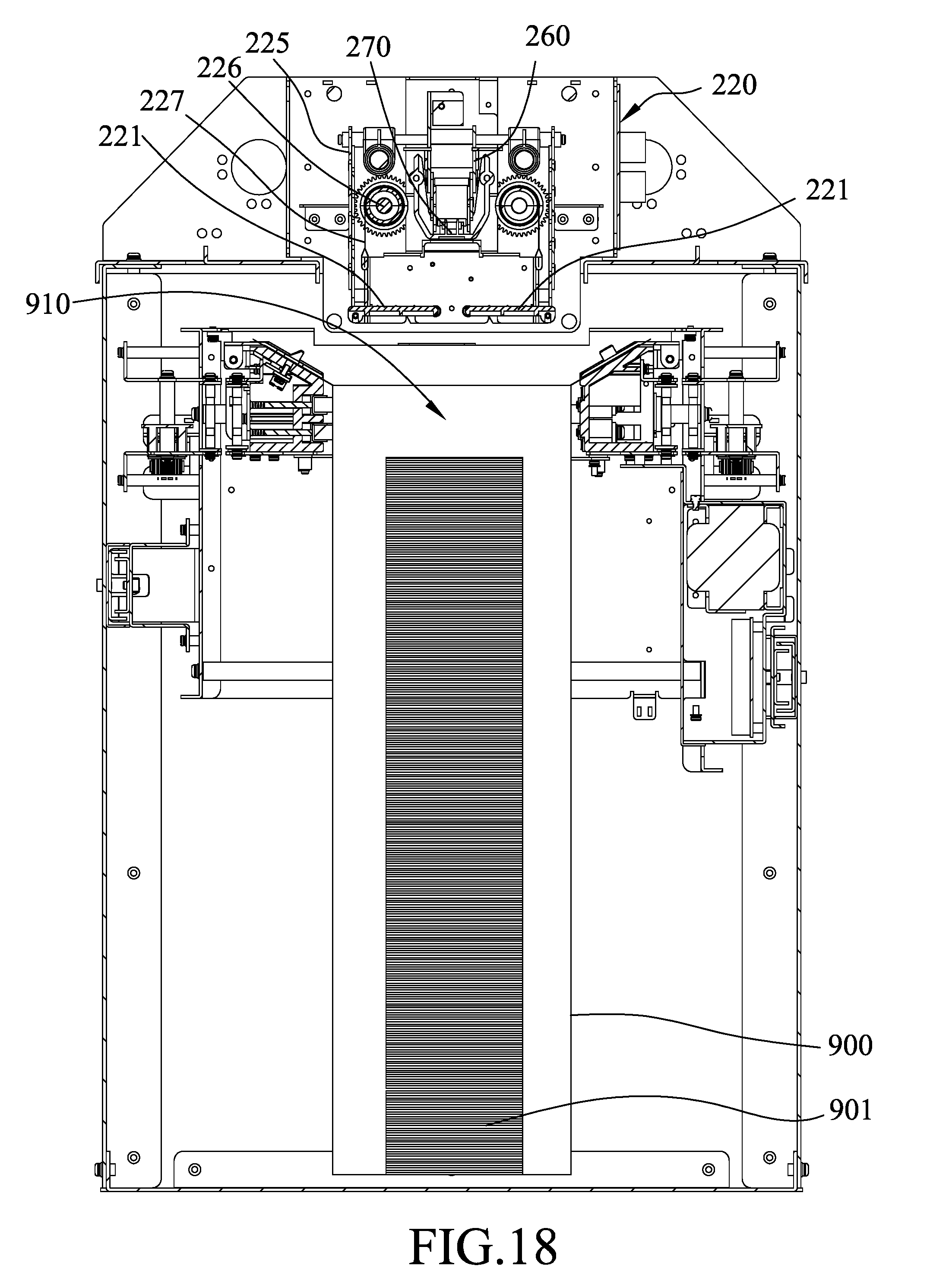
[0024] FIGS. 14 to 18 are sectional views showing operation of the embodiment.
DETAILED DESCRIPTION
[0025] Before the disclosure is described in greater detail, it should be noted that where considered appropriate, reference numerals or terminal portions of reference numerals have been repeated among the figures to indicate corresponding or analogous elements, which may optionally have similar characteristics.
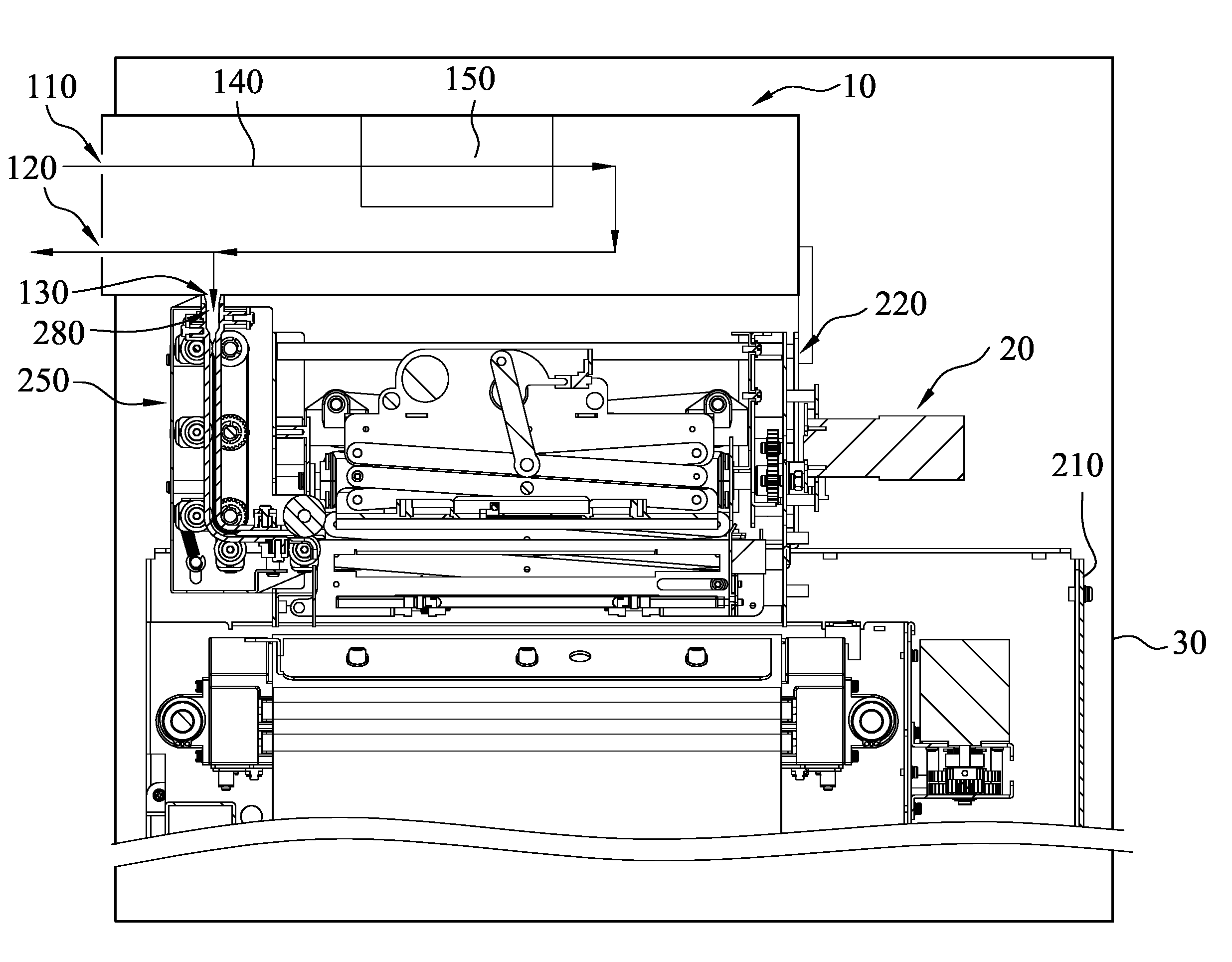
[0026] Referring to FIGS. 2 to 4, an embodiment of a paper sheet deposit machine 1 according to the present disclosure is adapted for storing a plurality of paper sheets 901 in a paper sheet storage bag 900. The paper sheet deposit machine 1 includes a paper sheet handling module 10, a paper sheet storage equipment 20 and a housing 30. The paper sheet handling module 10 and the paper sheet storage equipment 20 are at least partially received in the housing 30. The paper sheet handling module 10 includes an inlet 110, an outlet 120, an opening 130, a discrimination unit 150, and an upper conveying path 140 that connects the inlet 110, the discrimination unit 150, the outlet 120 and the opening 130. In this embodiment, the paper sheets 901 are bank notes. In certain embodiments, the paper sheets 901 may be checks or other sheets of paper, and should not be limited by the embodiment of this application.
[0027] The discrimination unit 150 is configured to discriminate at least one feature of each of the paper sheets 901, allows the paper sheets 901 that pass the discrimination to be conveyed to the opening 130, and allows the paper sheets 901 that fail to pass the discrimination to be conveyed to the outlet 120. The paper sheet storage equipment 20 has a lower opening 280 that is communicated with the opening 130 of the paper sheet handling module 10. That is, the paper sheets 901 are conveyed along the upper conveying path 140 from the inlet 110 to reach the discrimination unit 150. The paper sheets 901 passing the discrimination would be further conveyed along the upper conveying path 140 to reach the opening 130, and to enter the paper sheet storage equipment 20.
[0028] The paper sheet storage equipment 20 includes an inner housing 210 disposed in the housing 30, a temporary storage unit 220, a bag installation unit 230 and a sealing unit 240.
[0029] The bag installation unit 230 is disposed inside the inner housing 210, and is adapted for the paper sheet storage bag 900 to be installed thereon. In this embodiment, the bag installation unit 230 are configured as two protrusions (see FIG. 4) adapted for the paper sheet storage bag 900 to be installed (i.e., held) thereon. In certain embodiments, the bag installation unit 50 holds the paper sheet storage bag 900 by clamping, velcroing, buttoning, zippering, etc., and may be changed according to practical requirements.
[0030] Referring further to FIGS. 5 to 7, in this embodiment, the paper sheet storage equipment further includes a lower conveying unit 250 connected between the paper sheet handling module 20 and the temporary storage unit 220. The lower conveying unit 250 includes a wheel unit 251, which includes a plurality of friction wheel sets 252 and a deformation wheel set 253 disposed downstream of the friction wheel sets 252. Each of the friction wheel sets 252 includes a driving wheel 2521 and a driven wheel 2522. The deformation wheel set 253 includes two spaced apart first wheels 2531, and a second wheel 2532 disposed between the first wheels 2531 and having a diameter larger than that of each of the first wheels 2531.
[0031] Referring to FIGS. 8 to 10, the temporary storage unit 220 includes two supporting plates 221, a limiting member 222, a seat 223, two torsion springs 224. The supporting plates 221 cooperatively define a temporary storage region (TSR) (see FIG. 13) that is spatially communicated with the opening 130. In this embodiment, the lower conveying unit 250 is connected between the opening 130 and the temporary storage region (TSR), allowing the paper sheets 901 to be conveyed through the opening 130 and the lower conveying unit 40 to be disposed at the temporary storage region (TSR) and on the supporting plates 221. Each of the paper sheets 901 passing through the lower conveying unit 250 is conveyed between the driving wheel 2521 and the driven wheel 2522 of each of the friction wheel sets 252 through friction, and is then deformed by the deformation wheel set 253. Specifically, referring to FIG. 7, when one of the paper sheets 901 passes through the deformation wheel set 253, a center portion of the paper sheet 901 is deformed by the second wheel 2532 to form a substantial V shape, thereby increasing the overall toughness of the paper sheet 901, and ensuring each of the paper sheets 901 passing through the deformation wheel set 253 to be more precisely stacked on the supporting plates 221.
[0032] In this embodiment, the supporting plates 221 are horizontally spaced apart from each other, and each of the supporting plates 221 is pivotably connected to the seat 223. The torsion springs 224 are connected to the seat 223. Each of the torsion springs 224 has two ends that respectively abut against the seat 223 and a respective one of the supporting plates 221 for biasing a corresponding one of the supporting plates 221 to a horizontal position.
[0033] The limiting member 222 is movably connected to the seat 223, and is operable to engage the supporting plates 221 (see FIG. 9 and the upper part of FIG. 10), such that the supporting plate 221 is adapted to support the paper sheets 901, and is operable to disengage the supporting plates 221 (see the lower part of FIG. 10), such that the supporting plates 221 are pressed by the paper sheets 901 and are thus swingable to allow the paper sheets 901 to drop into the paper sheet storage bag 900. In this embodiment, the limiting member 222 is movable in a direction (D) as indicated by an arrow in FIGS. 9 and 10 to disengage the supporting plates 221. Specifically, when the limiting member 222 engages the supporting plates 221, the supporting plates 221 are horizontal and cooperate with each other to support the paper sheets 901. When the limiting member 222 disengages the supporting plates 221, each of the supporting plates 221 is swingable downwardly due to the gravitational force of the paper sheets 901, so that the paper sheets 901 drop into the paper sheet storage bag 900. After the paper sheets 901 separate from the supporting plates 221, the torsion springs 224 bias and return each of the supporting plates 221 to the horizontal position.
[0034] In this embodiment, each of the supporting plates 221 has a protrusion 2211. The limiting member 222 has two spaced apart horizontal slots 2221 each having an open end, and the horizontal slots 2221 are opened in the same direction. The limiting member 222 is operable to move between an engaging position (see FIG. 9 and the upper part of FIG. 10), where the horizontal slots 2221 of the limiting member 222 respectively engage the protrusions 2211 of the supporting plates 221, and a disengaging position (see the lower part of FIG. 10), where the horizontal slots 2221 of the limiting member 222 are disengaged from the protrusions 2211 of the supporting plates 221. The limiting member 222 may be actuated by a solenoid actuator 228, which may be replaced by other actuating mechanism based on actual requirements.
[0035] Referring to FIG. 11, in a variation of this embodiment, each of the supporting plates 221 is formed with a pin hole 2212. The limiting member 222 has two spaced apart pins 2222. The limiting member 222 is operable to move between the engaging position, where the pins 2222 of the limiting member 222 are respectively inserted into the pin holes 2212 of the supporting plates 221 to hold each of the supporting plates 221 at the horizontal position, and a disengaging position, where the pins 2222 of the limiting member 222 are respectively disengaged from the pin holes 2212 of the supporting plates 221. In this embodiment, the limiting member 222 is movable in a direction (D') as indicated by an arrow in FIG. 11 to disengage the supporting plates 221.
[0036] Referring to FIG. 12, in another variation of this embodiment, the limiting member 222 has two spaced apart protrusions 2223. The limiting member 222 is operable to move between the engaging position, where the protrusions 2223 of the limiting member 222 are respectively underneath the supporting plates 221 for blocking each of the supporting plates 221 from downward pivotal movement from the horizontal position, and the disengaging position, where the limiting member 222 is horizontally spaced apart from the supporting plates 221 to allow the supporting plates 221 to pivot downwardly. In this embodiment, the limiting member 222 is movable in a direction (D'') as indicated by an arrow in FIG. 12 to disengage the supporting plates 21.
[0037] Referring to FIGS. 4 and 8, the temporary storage unit 220 further includes an extendable member 225 that is connected between the inner housing 210 and the seat 223. In this embodiment, the extendable member 225 has a deployable scissor structure, and may be changed according to practical requirements. In this embodiment, the temporary storage unit 220 further includes a roller 226 that is connected to the inner housing 210, and a film 227 that is rolled on the roller 226 and that has an end connected to the seat 223. The roller 226 is operable by an actuator (not shown) to release the film 227 from the roller 226, the limiting member 222, the supporting plates 221 and the torsion springs 224 to move downwardly, or to roll the film 227 thereon so as to pull the seat 223, the limiting member 222, the supporting plates 221 and the torsion springs 224 to move upwardly. Since the extendable member 225 has one end connected to the seat 223, the extendable member 225 would be extended when the seat 223 is moved downwardly. In other words, the extendable member 225 is operable by the rolling or unrolling of the roller 226 to vertically move the seat 223, the limiting member 222, the supporting plates 221 and the torsion springs 224 above or in the paper sheet storage bag 900. The purpose of the abovementioned vertical movement is to adjust the altitude of the supporting plates 221 according to the amount of paper sheets 901 contained in the paper sheet storage bag 900. The film 227 separates the paper sheets 901 from the extendable member 225 to prevent the paper sheets 901 from being clamped by the extendable member 225. Besides being extendable, the extendable member 225 also has superior mechanical strength.
[0038] Referring to FIG. 4, the sealing unit 240 is disposed on the inner housing 210, and includes a tab 241 that is disposed adjacent to an upper end of the paper sheet storage bag 900, and a heating member 242 that is operable to heat the tab 241. When the tab 241 is heated by the heating member 242, it is operable to abut against and seal a bag opening 910 of the paper sheet storage bag 900 by heat sealing.
[0039] Referring to FIGS. 13 to 18, the paper sheet storage equipment 20 further includes an extendable unit 260 that is disposed above the supporting plates 21, and a sensor 270 that is disposed at a lower end of the extendable unit 260. The sensor 270 may be an infrared sensor configured to measure the amount of paper sheets 901 stacked on the supporting plates 21, thereby ensuring enough temporary storage region (TSR) for storing the paper sheets 901. FIG. 14 shows that the paper sheets 901 are starting to be stacked on the supporting plates 21. FIG. 15 shows that the extendable member 225 extends downwardly with more paper sheets 901 are stacked on the supporting plates 21. After a certain amount of paper sheets 901 are stacked on the supporting plates 21 (see FIG. 15), the limiting member 22 is moved to the disengaging position to allow some of the paper sheets 901 to drop into the paper sheet storage bag 900 (see FIG. 16). Specifically, since the weight of the paper sheets 901 stacked on the supporting plates 21 is greater than the weight that the torsion springs 224 can withstand, the supporting plates 21 is downwardly swingable due to the weight of the paper sheets 901 stacked thereon, thereby allowing some of the paper sheets 901 to drop into the paper sheet storage bag 900, and the supporting plates 21 will be biased by the torsion springs 224 to return to the horizontal position when the weight of the paper sheets 901 remaining on the supporting plates 21 is less than the weight that the torsion springs 224 can withstand. To ensure that there are certain amount of paper sheets 901 left on the supporting plates 21, the sensor 270 senses that if there is any paper sheet 901 left on the supporting plates 21, and the extendable unit 260 will be driven to a predetermined altitude. Meanwhile, the extendable member 225 is driven to move the supporting plates 21 upwardly, allowing the paper sheets 901 left on the supporting plates 21 to abut against the extendable unit 260. Since the extendable unit 260 is fixed at the predetermined altitude, and the supporting plates 21 are continuously moved upward by the extendable member 225, the paper sheets 901 left on the supporting plates 21 will abut against the extendable unit 260, allowing the supporting plates 21 to rotate downwardly to form an opening for the paper sheets 901 to pass through the opening and drop into the paper sheet storage bag 900.
[0040] The limiting member 222 and the supporting plates 221 of this disclosure provide a simplified and efficient mechanism to control the paper sheets 901 to be stacked on the supporting plates 221 or to be released into the paper sheet storage bag 900.
[0041] In the description above, for the purposes of explanation, numerous specific details have been set forth in order to provide a thorough understanding of the embodiments. It will be apparent, however, to one skilled in the art, that one or more other embodiments may be practiced without some of these specific details. It should also be appreciated that reference throughout this specification to "one embodiment," "an embodiment," an embodiment with an indication of an ordinal number and so forth means that a particular feature, structure, or characteristic may be included in the practice of the disclosure. It should be further appreciated that in the description, various features are sometimes grouped together in a single embodiment, figure, or description thereof for the purpose of streamlining the disclosure and aiding in the understanding of various inventive aspects.
[0042] While the disclosure has been described in connection with what are considered the exemplary embodiments, it is understood that this disclosure is not limited to the disclosed embodiment and modifications but is intended to cover various arrangements included within the spirit and scope of the broadest interpretation so as to encompass all such modifications and equivalent arrangements.
* * * * *
D00000
D00001
D00002
D00003
D00004
D00005
D00006
D00007
D00008
D00009
D00010
D00011
D00012

D00013

D00014
D00015
D00016

D00017

D00018
XML
uspto.report is an independent third-party trademark research tool that is not affiliated, endorsed, or sponsored by the United States Patent and Trademark Office (USPTO) or any other governmental organization. The information provided by uspto.report is based on publicly available data at the time of writing and is intended for informational purposes only.
While we strive to provide accurate and up-to-date information, we do not guarantee the accuracy, completeness, reliability, or suitability of the information displayed on this site. The use of this site is at your own risk. Any reliance you place on such information is therefore strictly at your own risk.
All official trademark data, including owner information, should be verified by visiting the official USPTO website at www.uspto.gov. This site is not intended to replace professional legal advice and should not be used as a substitute for consulting with a legal professional who is knowledgeable about trademark law.