Full Display Rearview Device
Minikey, JR.; Danny L. ; et al.
U.S. patent application number 16/143083 was filed with the patent office on 2019-01-24 for full display rearview device. This patent application is currently assigned to Gentex Corporation. The applicant listed for this patent is Gentex Corporation. Invention is credited to Richard T. Fish, JR., Jason D. Hallack, Bradley R. Hamlin, Michael F Lisowski, Danny L. Minikey, JR..
| Application Number | 20190023185 16/143083 |
| Document ID | / |
| Family ID | 57320602 |
| Filed Date | 2019-01-24 |


View All Diagrams
| United States Patent Application | 20190023185 |
| Kind Code | A1 |
| Minikey, JR.; Danny L. ; et al. | January 24, 2019 |
FULL DISPLAY REARVIEW DEVICE
Abstract
A display mirror assembly having a mount operably coupled to a vehicle interior. The mount includes one of a ball and a socket extending forwardly therefrom. An engagement plate is pivotally coupled with the mount via the other of a ball and a socket extending rearwardly from the engagement plate. The engagement plate includes a first support member and a second support member pivotally coupled to the first support member. A carrier plate is operably coupled with the engagement plate. The carrier plate supports a rear housing on a rear portion thereof. A glass element is operably coupled with the carrier plate. A display module is configured to be turned to an on state and an off state. An actuator device is disposed on a bottom surface of the housing and is operably coupled with the glass element. The actuator device is adjustable to tilt the glass element.
| Inventors: | Minikey, JR.; Danny L.; (Fenwick, MI) ; Fish, JR.; Richard T.; (Hudsonville, MI) ; Hamlin; Bradley R.; (Allendale, MI) ; Lisowski; Michael F; (Holland, MI) ; Hallack; Jason D.; (Allendale, MI) | ||||||||||
| Applicant: |
|
||||||||||
|---|---|---|---|---|---|---|---|---|---|---|---|
| Assignee: | Gentex Corporation Zeeland MI |
||||||||||
| Family ID: | 57320602 | ||||||||||
| Appl. No.: | 16/143083 | ||||||||||
| Filed: | September 26, 2018 |
Related U.S. Patent Documents
| Application Number | Filing Date | Patent Number | ||
|---|---|---|---|---|
| 15157056 | May 17, 2016 | 10112540 | ||
| 16143083 | ||||
| 62163226 | May 18, 2015 | |||
| Current U.S. Class: | 1/1 |
| Current CPC Class: | B60R 2001/1253 20130101; B60R 1/12 20130101; B60R 1/04 20130101; B60R 2001/1223 20130101; B60R 1/0612 20130101; B60R 1/072 20130101; B60R 1/087 20130101 |
| International Class: | B60R 1/12 20060101 B60R001/12; B60R 1/08 20060101 B60R001/08; B60R 1/06 20060101 B60R001/06; B60R 1/04 20060101 B60R001/04; B60R 1/072 20060101 B60R001/072 |
Claims
1. A display mirror assembly comprising: a mount configured to be operably coupled to an interior of a vehicle; a carrier plate; a mounting member disposed between the mount and the carrier plate and operably connecting the carrier plate and the mount; a front shield attached to the carrier plate, the front shield having a generally ring shape forming an opening; a display module disposed between the carrier plate and the front shield, the display module including a display viewable through the opening of the front shield; a glass element connected to the front shield, and the display module is viewable through the glass element; and a rear housing including a cavity in which the front shield, the carrier plate, and the display module are at least partially disposed; wherein, the carrier plate and the front shield are configured to shield the display module from radio frequency electromagnetic radiation; and wherein, the carrier plate generally bears the weight of the display mirror assembly on the mount.
2. The display mirror assembly of claim 1, the mount including one of a ball and a socket; and the mounting member having the other of the ball and a socket.
3. The display mirror assembly of claim 1, the mount configured to be coupled to a windshield of the vehicle.
4. The display mirror assembly of claim 1, the carrier plate and the front shield comprising stamped steel.
5. The display mirror assembly of claim 1, the display module further including an optic stack, an optic tray, a main printed circuit board, and a heat sink.
6. The display mirror assembly of claim 5, wherein, the display, the optic stack, the main printed circuit board, and the heat sink are so ordered from the front shield toward the carrier plate.
7. The display mirror assembly of claim 5, the display module further including a secondary printed circuit board electrically connected with the main printed circuit board, the secondary printed circuit board having a width that extends along a top edge of the display.
8. The display mirror assembly of claim 1, the glass element including a border that incorporates an edge treatment to conceal the front shield from view.
9. The display mirror assembly of claim 1, the display module further including a main printed circuit board that is in electrical communication with the glass element.
10. The display mirror assembly of claim 1, the glass element being adhered to the front shield.
11. The display mirror assembly of claim 1 further comprising: an adjustable actuator device that selectively tilts the glass element in a first direction or a second direction, such that in the first direction the glass element is in an off-axis position and in the second direction the glass element is in an on-axis position.
12. The display mirror assembly of claim 11, adjusting the actuator device additionally changes an on/off state of the display, such that when the actuator device is adjusted to tilt the glass element to the off-axis position, the actuator device turns the display off.
13. The display mirror assembly of claim 11, adjusting the actuator device moves the carrier plate, and the rear housing moves with the carrier plate.
14. The display mirror assembly of claim 1, the glass element including outer perimeter; and the front shield including an outer surface that is generally coextensive with the outer perimeter of the glass element.
15. The display mirror assembly of claim 1 further comprising: a glare sensor disposed to a rear side of an optic tray of the display module.
16. The display mirror assembly of claim 15, the glare sensor receiving light through a light pipe that extends outside of the rear housing.
17. A display mirror assembly comprising: a front shield including a front side; a glass element adhered to the front side of the front shield; a display, an optic stack, and an optic tray attached to the front shield; a main printed circuit board attached to the optic tray and electro-optically connected to the glass element; a secondary printed circuit board attached to a heat sink forming a subassembly that is attached to the optic tray; a carrier plate attached to the front shield so as to encapsulate the display, the optic stack, the optic tray, the main printed circuit board, and the secondary printed circuit board between the carrier plate and the front shield; and a rear housing attached to a rear portion of the carrier plate.
18. The display mirror assembly of claim 17, the secondary printed circuit board attached to the heat sink with a thermally conductive adhesive.
19. The display mirror assembly of claim 18, the carrier plate operably connected to a mount that is configured to be attached to a windshield of a vehicle; and the carrier plate generally bears the weight of the display mirror assembly on the mount.
20. A display mirror assembly comprising: a mount operably coupled to a vehicle interior; a carrier plate operably coupled with the mount, the carrier plate having a rear portion and the carrier plate at least partially bearing the weight of a rear housing on the rear portion; a glass element operably coupled with the carrier plate; an optic stack disposed behind the glass element; a display being configured to be turned to an on state and an off state; and an actuator device operably coupled with the glass element, wherein the actuator device is adjustable to tilt the glass element in one direction, thereby moving the glass element to an off-axis position which approximately simultaneously changes the on/off state of the display, and wherein the actuator device is also adjustable to tilt the glass element in another direction, thereby moving the glass element to an on-axis position which approximately simultaneously changes the on/off state of the display.
Description
CROSS-REFERENCE TO RELATED APPLICATIONS
[0001] This application is a continuation of and claims priority to U.S. patent application Ser. No. 15/157,056, filed on May 17, 2016, entitled "FULL DISPLAY REARVIEW DEVICE," and the benefit under 35 U.S.C. .sctn. 119(e) of U.S. Provisional Application No. 62/163,226, filed on May 18, 2015, entitled "REARVIEW DEVICE," the disclosures of which are hereby incorporated herein by reference in their entirety.
BACKGROUND OF THE DISCLOSURE
[0002] The present disclosure generally relates to a rearview device system, and more particularly, to a full display rearview device having a partially reflective, partially transmissive element and a display behind the reflective element.
SUMMARY OF THE DISCLOSURE
[0003] One aspect of the disclosure includes a display mirror assembly having a mount operably coupled to a vehicle interior. The mount includes one of a ball and a socket extending forwardly therefrom. An engagement plate is pivotally coupled with the mount via the other of a ball and a socket extending rearwardly from the engagement plate. The engagement plate includes a first support member and a second support member pivotally coupled to the first support member. A carrier plate is operably coupled with the engagement plate. The carrier plate supports a rear housing on a rear portion thereof. A glass element is operably coupled with the carrier plate. A display module is configured to be turned to an on state and an off state. An actuator device is disposed on a bottom surface of the housing and is operably coupled with the glass element. The actuator device is adjustable to tilt the glass element in one direction, thereby moving the glass element to an off-axis position which approximately simultaneously changes the on/off state of the display module, and wherein the actuator device is also adjustable to tilt the glass element in another direction, thereby moving the glass element to an on-axis position which approximately simultaneously changes the on/off state of the display module.
[0004] Another aspect of the disclosure includes a display mirror assembly having a mount operably coupled to a vehicle interior. The mount includes one of a ball and a socket extending forwardly therefrom. A carrier plate is operably coupled with an engagement plate. The carrier plate supports a rear housing on a rear portion thereof. A glass element is operably coupled with the carrier plate. An optic stack is disposed behind the glass element. A glare sensor is operably coupled with the glass element and is in optical communication with a light pipe that is exposed to an exterior of the display mirror assembly. A display module is configured to be turned to an on state and an off state. An actuator device is disposed on a bottom surface of the housing and is operably coupled with the glass element. The actuator device is adjustable to tilt the glass element in one direction, thereby moving the glass element to an off-axis position which approximately simultaneously changes the on/off state of the display module, and wherein the actuator device is also adjustable to tilt the glass element in another direction, thereby moving the glass element to an on-axis position which approximately simultaneously changes the on/off state of the display module.
[0005] Still another aspect of the disclosure includes a display mirror assembly having a mount operably coupled to a vehicle interior. The mount includes one of a ball and a socket extending forwardly therefrom. A carrier plate is operably coupled with an engagement plate. The carrier plate supports a rear housing on a rear portion thereof. A glass element is operably coupled with the carrier plate. A glare sensor is operably coupled with the carrier plate and is in optical communication with a light pipe that is exposed to an exterior of the display mirror assembly. A display module is configured to be turned to an on state and an off state. An actuator device is disposed on a bottom surface of the housing and is operably coupled with the glass element. The actuator device is adjustable to tilt the glass element in one direction, thereby moving the glass element to an off-axis position which approximately simultaneously changes the on/off state of the display module, and wherein the actuator device is also adjustable to tilt the glass element in another direction, thereby moving the glass element to an on-axis position which approximately simultaneously changes the on/off state of the display module.
[0006] Yet another aspect of the disclosure includes a display mirror assembly that is configured to provide an image via a liquid crystal display (LCD) of a scene rearward of a vehicle. During certain instances, as determined by a driver, the LCD can be deactivated by toggling an actuator device between forward and rearward positions. Even after the deactivation of the LCD, a rearward view of a vehicle can be seen by reflective member disposed inside the display mirror assembly. The display mirror assembly, as set forth herein, provides a multi-functional device that can be adjusted based on user preferences, which is easy to manufacture, and which is very robust.
[0007] These and other features, advantages, and objects of the present disclosure will be further understood and appreciated by those skilled in the art by reference to the following specification, claims, and appended drawings.
BRIEF DESCRIPTION OF THE DRAWINGS
[0008] FIG. 1 is a top perspective view of one embodiment of a display mirror assembly of the present disclosure;
[0009] FIG. 2 is a front elevational view of the display mirror assembly of FIG. 1;
[0010] FIG. 3 is a rear elevational view of the display mirror assembly of FIG. 1;
[0011] FIG. 4 is a top plan view of the display mirror assembly of FIG. 1;
[0012] FIG. 5 is a bottom plan view of the display mirror assembly of FIG. 1;
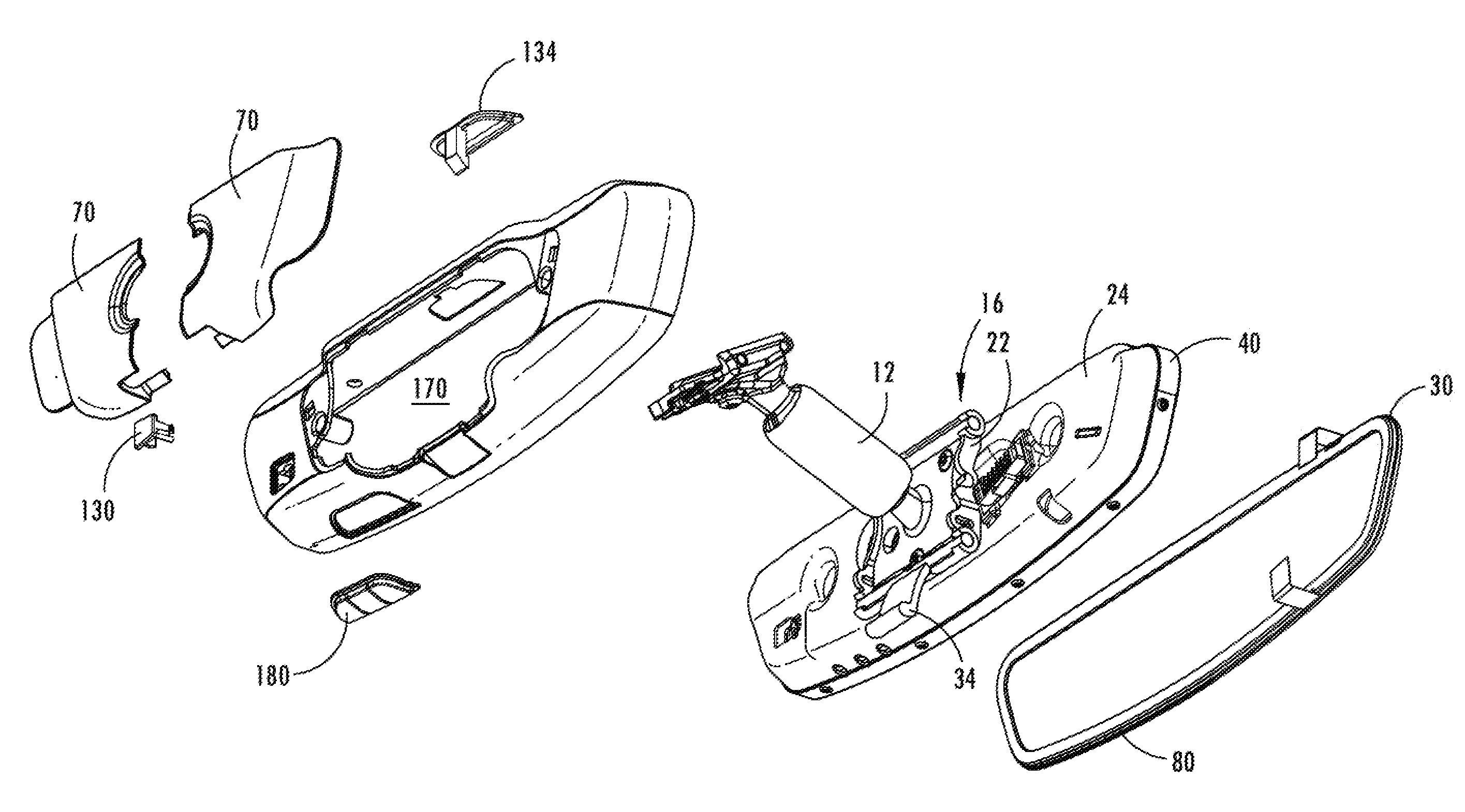
[0013] FIG. 6 is a front perspective partially exploded view of the display mirror assembly of FIG. 1;
[0014] FIG. 6A is a rear perspective partially exploded view of the display mirror assembly of FIG. 1;
[0015] FIG. 7 is a front perspective exploded view of internal components of the display mirror assembly of FIG. 1;
[0016] FIG. 7A is a rear perspective exploded view of internal components of the display mirror assembly of FIG. 1;
[0017] FIG. 8 is a front perspective partial exploded view of internal components the display mirror assembly of FIG. 1;
[0018] FIG. 8A is a rear perspective partial exploded view of internal components the display mirror assembly of FIG. 1;
[0019] FIG. 8B is an enlarged partial cross-sectional view of the display mirror assembly of FIG. 1;
[0020] FIG. 8C is an enlarged partial cross-sectional view of the display mirror assembly of FIG. 1 taken at the glare sensor;
[0021] FIG. 9 is a bottom perspective view of the display mirror assembly of the present disclosure with an actuator device in a rearward position;
[0022] FIG. 10 is a side plan view of the display mirror assembly with the actuator device in a rearward position;
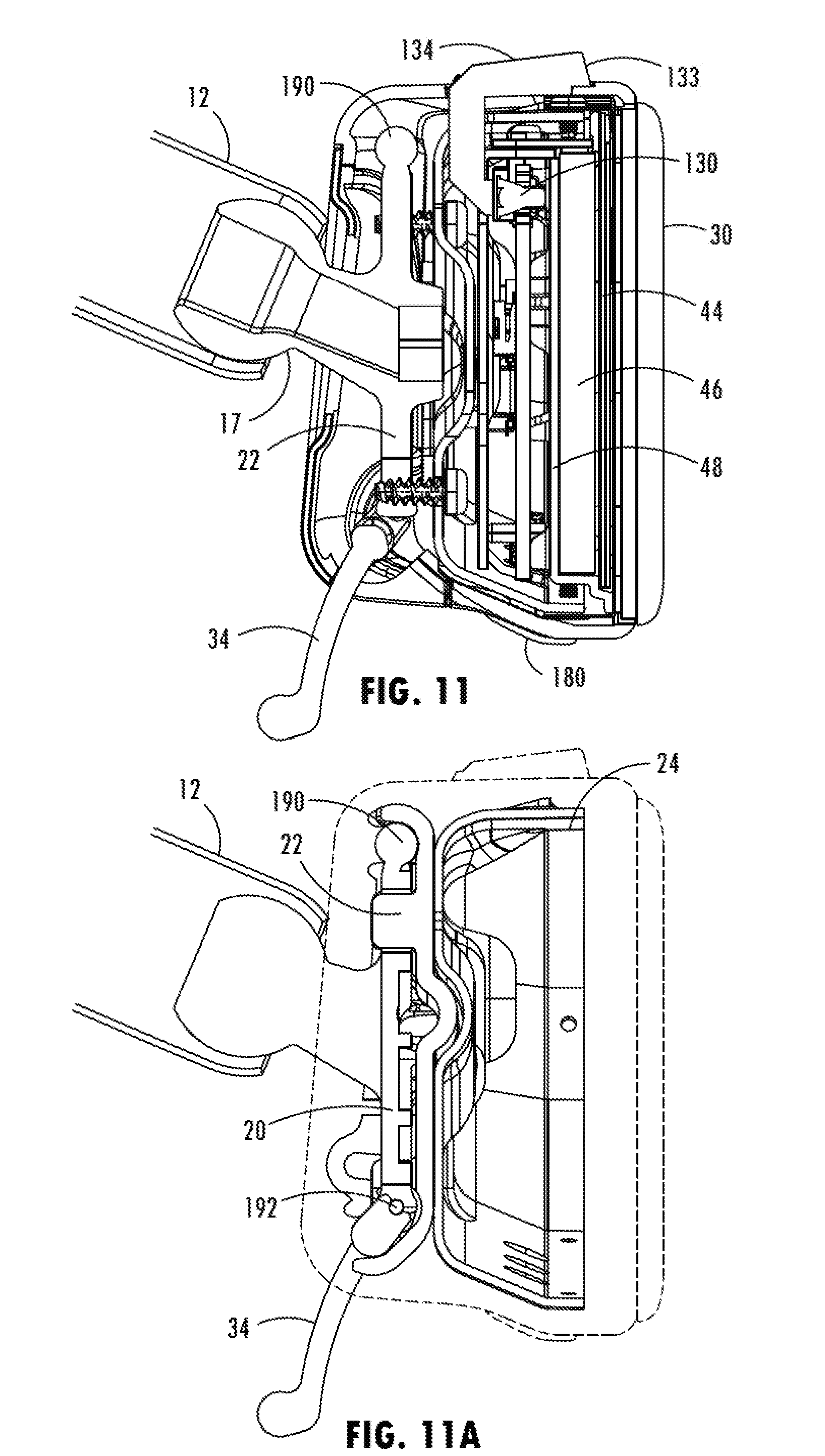
[0023] FIG. 11 is a side cross-sectional elevational view of the display mirror assembly with the actuator device in a rearward position;
[0024] FIG. 11A is a side cross-sectional elevational view of the display mirror assembly with the actuator device in the rearward position with the housing and internal components removed;
[0025] FIG. 12 is a bottom perspective view of the display mirror assembly of the present disclosure with an actuator device in a forward position;
[0026] FIG. 13 is a side plan view of the display mirror assembly with the actuator device in a forward position;
[0027] FIG. 14 is a side cross-sectional elevational view of the display mirror assembly with the actuator device in a forward position;
[0028] FIG. 14A is a side cross-sectional elevational view of the display mirror assembly with the actuator device in the forward position with the housing and internal components removed;
[0029] FIG. 15 is a front elevational view of a display mirror assembly of the present disclosure illustrating the distance from the active area to the edge; and
[0030] FIG. 16 is a front elevational view of a display mirror assembly of the present disclosure illustrating the distance from the active area to the edge of the glass element.
DETAILED DESCRIPTION
[0031] The present illustrated embodiments reside primarily in combinations of method steps and apparatus components related to a display mirror. Accordingly, the apparatus components and method steps have been represented, where appropriate, by conventional symbols in the drawings, showing only those specific details that are pertinent to understanding the embodiments of the present disclosure so as not to obscure the disclosure with details that will be readily apparent to those of ordinary skill in the art having the benefit of the description herein. Further, like numerals in the description and drawings represent like elements.
[0032] For purposes of description herein, the terms "upper," "lower," "right," "left," "rear," "front," "vertical," "horizontal," and derivatives thereof shall relate to the disclosure as oriented in FIG. 1. Unless stated otherwise, the term "front" shall refer to the surface of the element closer to an intended viewer of the display mirror, and the term "rear" shall refer to the surface of the element further from the intended viewer of the display mirror. However, it is to be understood that the disclosure may assume various alternative orientations, except where expressly specified to the contrary. It is also to be understood that the specific devices and processes illustrated in the attached drawings, and described in the following specification are simply exemplary embodiments of the inventive concepts defined in the appended claims. Hence, specific dimensions and other physical characteristics relating to the embodiments disclosed herein are not to be considered as limiting, unless the claims expressly state otherwise.
[0033] The terms "including," "comprises," "comprising," or any other variation thereof, are intended to cover a non-exclusive inclusion, such that a process, method, article, or apparatus that comprises a list of elements does not include only those elements but may include other elements not expressly listed or inherent to such process, method, article, or apparatus. An element proceeded by "comprises a . . . " does not, without more constraints, preclude the existence of additional identical elements in the process, method, article, or apparatus that comprises the element.
[0034] Referring now to FIGS. 1-16, reference numeral 10 generally designates a display mirror assembly having a mount 12 operably coupled to a vehicle interior. The mount 12 includes one of a ball and a socket 14 extending forwardly therefrom. An engagement plate 16 is pivotally coupled with the mount 12 via a mounting member 17 having the other of a ball and a socket 14 extending rearwardly from the engagement plate 16. The engagement plate 16 includes a first support member 20 and a second support member 22 pivotally coupled to the first support member 20. A carrier plate 24 is operably coupled with the engagement plate 16. The carrier plate 24 supports a rear housing 26 on a rear portion 28 thereof. A glass element 30 is operably coupled with the carrier plate 24. A display module 32 is configured to be turned to an on state and an off state. An actuator device 34 is disposed on a bottom surface of the rear housing 26 and is operably coupled with the glass element 30. The actuator device 34 is adjustable to tilt the glass element 30 in one direction, thereby moving the glass element 30 to an off-axis position which approximately simultaneously changes the on/off state of the display module 32, and wherein the actuator device 34 is also adjustable to tilt the glass element 30 in another direction, thereby moving the glass element 30 to an on-axis position which approximately simultaneously changes the on/off state of the display module 32.
[0035] As referenced above, the reference numeral 10 generally designates a rearview device in the form of a display mirror assembly for a vehicle. The display mirror assembly 10 includes the partially reflective, partially transmissive element 30 (also referred to as a "glass element" herein). The display module 32 is viewable through the partially reflective, partially transmissive element 30. The display mirror assembly 10 further includes a front shield 40 and a carrier plate 24, which shield and support the partially reflective, partially transmissive element 30 and the display module 32. The display module 32 generally includes several components, including a display 44, an optic stack 46, an optic tray 48, a main printed circuit board (PCB) 50, and a heat sink 52. The rear housing 26 at least partially receives the front shield 40, the display module 32, and the carrier plate 24. The rear housing 26 covers a rear portion of the carrier plate 24, but does not structurally support the display mirror assembly 10. The carrier plate 24, however, supports the entire rearview device 10 via a mounting member 17 extending rearwardly therefrom. The mounting member 17 is adapted for connection with the mount 12 coupled to a windshield of a vehicle.
[0036] Referring generally to FIG. 1, the display mirror assembly 10 has a viewing area 60, which includes a front surface 62 of the glass element 30. The viewing area 60 may be a rectangular shape, a trapezoidal shape, or any custom contoured shape desired for aesthetic reasons.
[0037] Referring to FIGS. 6 and 6A, the display mirror assembly 10 for a vehicle is shown, with the internal components partially exploded. The display mirror assembly 10 includes the glass element 30, the front shield 40, and the carrier plate 24 encapsulating the display module 32, the rear housing 26, rear coverplates 70, and the mounting member 17. As shown in FIGS. 7 and 7A, the front shield 40, the carrier plate 24, and components of the display module 32 include various retaining features to operably connect the several components of the display module 32 with the front shield 40, the carrier plate 24, and each other, and to provide support to the display module 32. Specifically, the front shield 40 includes retaining features to operably couple the front shield 40 to the display module 32, and the carrier plate 24 has retaining features to operably couple the carrier plate 24 to the display module 32. The retaining features generally include snap fit connections, tab and slot connections, screw connections, and other known retaining features. Some or all of the retaining features may also be strengthened by the addition of adhesive compounds. Certain non-limiting illustrative examples of retaining features are described in detail herein.
[0038] The display mirror assembly 10 will hereafter be described in greater detail, beginning with the elements closest to the intended viewer, and extending rearwardly away from the viewer.
[0039] As shown in FIGS. 1-4, 6, and 6A, the glass element 30 is generally planar, with an outer perimeter 80 and a border 82 around the outer perimeter 80. The border 82 may incorporate an edge treatment, such as a chrome ring, or other similar finish, to conceal the front shield 40 and other elements located behind the glass element 30 in the display mirror assembly 10, including, without limitation, a seal on an electro-optic unit, an applique, foam adhesive, or pad printing. The border 82 may extend from the outer perimeter 80 of the glass element 30 to an outer edge of the display 44. Alternatively, the border 82 may be narrower and not reach from the outer perimeter 80 to the outer edge of the display 44 along at least some portions of the border 82. The outer perimeter 80 of the glass element 30 may also have a ground edge, a bezeled edge, or be frameless.
[0040] The glass element 30 may be an electro-optic element or an element such as a prism. One non-limiting example of an electro-optic element is an electrochromic medium, which includes at least one solvent, at least one anodic material, and at least one cathodic material. Typically, both of the anodic and cathodic materials are electroactive and at least one of them is electrochromic. It will be understood that regardless of its ordinary meaning, the term "electroactive" will be defined herein as a material that undergoes a modification in its oxidation state upon exposure to a particular electrical potential difference. Additionally, it will be understood that the term "electrochromic" will be defined herein, regardless of its ordinary meaning, as a material that exhibits a change in its extinction coefficient at one or more wavelengths upon exposure to a particular electrical potential difference. Electrochromic components, as described herein, include materials whose color or opacity are affected by electric current, such that when an electrical current is applied to the material, the color or opacity change from a first phase to a second phase. The electrochromic component may be a single-layer, single-phase component, multi-layer component, or multi-phase component, as described in U.S. Pat. No. 5,928,572 entitled "Electrochromic Layer And Devices Comprising Same," U.S. Pat. No. 5,998,617 entitled "Electrochromic Compounds," U.S. Pat. No. 6,020,987 entitled "Electrochromic Medium Capable Of Producing A Pre-selected Color," U.S. Pat. No. 6,037,471 entitled "Electrochromic Compounds," U.S. Pat. No. 6,141,137 entitled "Electrochromic Media For Producing A Pre-selected Color," U.S. Pat. No. 6,241,916 entitled "Electrochromic System," U.S. Pat. No. 6,193,912 entitled "Near Infrared-Absorbing Electrochromic Compounds And Devices Comprising Same," U.S. Pat. No. 6,249,369 entitled "Coupled Electrochromic Compounds With Photostable Dication Oxidation States," and U.S. Pat. No. 6,137,620 entitled "Electrochromic Media With Concentration Enhanced Stability, Process For The Preparation Thereof and Use In Electrochromic Devices"; U.S. Pat. No. 6,519,072, entitled "Electrochromic Device"; and International Patent Application Serial Nos. PCT/US98/05570 entitled "Electrochromic Polymeric Solid Films, Manufacturing Electrochromic Devices Using Such Solid Films, And Processes For Making Such Solid Films And Devices," PCT/EP98/03862 entitled "Electrochromic Polymer System," and PCT/US98/05570 entitled "Electrochromic Polymeric Solid Films, Manufacturing Electrochromic Devices Using Such Solid Films, And Processes For Making Such Solid Films And Devices," which are herein incorporated by reference in their entirety. The glass element may also be any other element having partially reflective, partially transmissive properties. To provide electric current to the glass element 30, electrical elements are provided on opposing sides of the element, to generate an electrical potential therebetween. Element clips 89, such as J-clips, are electrically engaged with each electrical element, and element wires extend from the J-clips to the main PCB.
[0041] Now referring to FIGS. 7 and 7A, the front shield 40 functions to shield the display module 32 from radio frequency (RF) electromagnetic radiation and to provide support for the glass element 30 and the display module 32. The front shield 40 is formed from one or more materials which are suitable to block RF radiation, including without limitation steel. As a non-limiting example, the front shield 40 can be formed from a stamped steel material.
[0042] Referring again to FIGS. 7 and 7A, the front shield 40 is generally shaped in the form of a ring having an opening therethrough. The front shield 40 has a front side 90, a rear side 92, and an outer surface 94, which is generally coextensive with the outer perimeter 80 of the glass element 30. The front shield 40 includes retaining features 96 extending therefrom, to mechanically engage the glass element 30. An adhesive, such as a foam adhesive, may also be used to secure the glass element 30 to the front shield 40. The front shield 40 further includes tabs 98 to operably engage the carrier plate 24 (or a component of the display module). The tabs 98 further include holes therethrough, to operably engage at least one component of the display module 32, such as the optic stack 46.
[0043] As best shown in FIGS. 8 and 8A, the display module 32 is disposed behind the front shield 40, with the display 44 viewable through the opening in the front shield 40. The components of the display module 32 are ordered, from the front shield 40 toward the carrier plate 24, the display 44, the optic stack 46, the optic tray 48, the main PCB 50, and the heat sink 52.
[0044] The display 44 is generally planar, with an outer edge 100 defining a front surface 102. The front surface 102 of the display 44 can be shaped to correspond to and fit within the shape of the viewing area 60 of the display mirror assembly 10. Alternatively, the display 44 may have a front surface 102 which fits within, but is not complementary to the viewing area 60, for example, where the front surface 102 of the display 44 is generally rectangular and the front surface 62 of the glass element 30 has a contoured outer perimeter. The distance between the outer edge 100 of the display 44 and the outer perimeter 80 of the glass element 30 is about 9 mm or less along at least a portion of the outer edge 100. In one embodiment, the display 44 has a viewable front surface area which is about 56% to about 70% of the viewing area 60 of the glass element 30. The display 44 includes tabs 103 that engage the carrier plate 24.
[0045] The display 44 may be a liquid crystal display (LCD), a light-emitting diode (LED), an organic light-emitting diode (OLED), plasma, digital light processing (DLP), or other display technology. The display 44 is operably coupled with a secondary PCB 110, which is operably mechanically and electrically connected with the main PCB 50 via a flexible electrical connector. The flexible electrical connector has a length sufficient to extend over the components of the display module 32 between the display 44 and the main PCB 50, and at least a portion of the heat sink 52. The secondary PCB 110 also has a width which extends substantially along a top edge of the display 44. The secondary PCB 110, when operably coupled to the main PCB 50, aids in securing the components along a top edge of the display module 32.
[0046] As shown in FIGS. 8-8C, the optic stack 46 includes a front side 120 adjacent the display 44, a rear side 122 adjacent the optic tray 48, and an outer perimeter 124. The optic stack 46 further includes engagement tabs or an adhesive 126 extending therefrom around at least a portion of the outer perimeter 124. In alternate embodiments, the engagement tabs 126 for engaging the front shield 40, or the screw-receiving elements, or both, could be provided on different components of the display module 32.
[0047] As shown in FIGS. 6, 6A, and 8C, a glare sensor 130 is provided on a rear side 132 of the optic tray 48. The glare sensor 130 includes a light receiving area 133, which receives light through a light pipe 134 that extends outside the rear housing 26. The light pipe 134 receives light from headlamps of a trailing vehicle, and relays the same to the glare sensor 130, which measures information regarding the likely glare visible on the glass element 30 and communicates this information to the display mirror assembly 10 so that the display mirror assembly 10 can be optimized to allow viewing of the display 44 through the glass element 30. The light pipe 134 extends above the rear housing 26 and the carrier plate 24. However, it is contemplated that the light pipe 134 could extend to any portion of the exterior of the display mirror assembly 10. The optical vertical/horizontal pattern of the glare sensor 130 is symmetrical, so that orientation of the glare sensor 130 is not significant. The glare sensor 130 could also be an imager on a rear portion of the vehicle, wherein a signal representative of the received light is communicated from the glare sensor 130 to the display mirror assembly 10.
[0048] As shown in FIGS. 8A and 8B, the heat sink 52 is disposed rearwardly from the optic stack 46, and dissipates heat generated by the main PCB 50 and other components of the display module 32. The heat sink 52 has a generally planar body with a front side and a top wall 140. A plurality of apertures 142 open upwardly from the top wall 140 of the heat sink 52, for mechanical engagement via mechanical fasteners 144 with the carrier plate 24.
[0049] The main PCB 50 operates to provide electrical power and control for the components of the display module 32 and for the glass element 30. As shown in FIGS. 8-8C, the main PCB 50 is generally planar, with a front side 145, a rear side 146, and side edges 148. The front side 145 is facing the optic tray 48 and the rear side 146 is facing the heat sink 52. Electrical components are generally oriented on the rear side 146 of the main PCB 50, although these components could be arranged on the front side 145. The main PCB 50 includes an electrical connector 150 for operable electrical engagement with the electrical element wires of the glass element 30, an electrical connector 151 for operable electrical engagement with the secondary PCB 110, and an electrical connector 152 for operable electrical engagement with a wiring harness 154. Additional functional elements that may be provided on the display mirror assembly 10 may also be electrically connected to the main PCB 50, such as the glare sensor 130 and any other functional buttons or features of the display mirror assembly 10. The main PCB 50 further includes cutouts 156 along the top edge, to permit passage of the screws used to secure the carrier plate 24 to the components of the display module 32.
[0050] The carrier plate 24 functions to support the display mirror assembly 10 and to shield the display module 32 from RF radiation. Referring again to FIGS. 7 and 7A, the carrier plate 24 also serves to encapsulate the display module 32, and further interlock the components of the display mirror assembly 10. The carrier plate 24 is formed from a material which is suitable to block such radiation and provide the desired support for the display mirror assembly 10, such as steel. As a non-limiting example, the carrier plate 24 can be formed from stamped steel. Notably, the carrier plate 24 generally supports the display mirror assembly 10 on the mount 12.
[0051] The carrier plate 24 includes a rear wall 160 having an outer perimeter, and a peripheral wall 162 extending forwardly from the rear wall 160 about at least a portion of the outer perimeter 80. The peripheral wall 162 has slots 164 therein, which correspond to the upstanding tabs 103 along the top edge of the carrier plate 24. The carrier plate 24 further includes at least one mechanical fastener aperture therethrough to accommodate at least one mechanical fastener 166 that extends through the carrier plate 24 and into the components of the display module 32 to secure the carrier plate 24 to the display module 32.
[0052] The rear housing 26 includes a forwardly directed cavity 170, into which all or a portion of the front shield 40, the carrier plate 24, and the display module 32 supported therebetween are inserted. The rear housing 26 includes mechanically engaging features that couple with corresponding engagement features located on the carrier plate 24. The rear housing 26 and the rear coverplates 70 are generally decorative in nature and do not provide any load bearing support. A button assembly 180 is positioned in the rear housing 26.
[0053] With respect to the following description, the display mirror assembly 10 is considered "on-axis" when a line perpendicular to the plane of the glass element 30 extends toward the eyes of a viewer. Due to the display 44 being viewed through the glass element 30, any glare on the glass element 30 may interfere with the visibility of the display 44. When the display mirror assembly 10 is on-axis and is being used during night time driving conditions, headlights from a trailing vehicle (i.e., a vehicle driving behind the vehicle with the display mirror assembly 10) can cause a glare which is visible to the driver. According to one embodiment of the present disclosure, the actuator device 34, as shown in FIGS. 9-14A, is operably coupled to the display mirror assembly 10. When actuated, the actuator device 34 moves at least the glass element 30 off-axis (i.e., away from a direct line toward the driver's eyes). Typically, actuation of the actuator device 34 tilts the glass element 30 upwards (FIGS. 12-14A), to move the glass element 30 to an off-axis position. However, it should be appreciated that the actuator device 34 can be configured to move the glass element 30 in any direction with respect to the axis. The actuator device 34 can also be configured to move the display 44 upon activation. The actuator device 34 can also be configured to turn the display 44 on or off. Thus, when the actuator device 34 is actuated to move the glass element 30 off-axis, the display 44 can be turned off. As shown in FIGS. 15 and 16, the display mirror assembly 10 has a display area that complements the shape of the glass element 30 and nearly fills the front surface of the glass element 30, leaving only a small peripheral edge.
[0054] Additionally, to provide information to the viewer of the display mirror assembly 10, the display mirror assembly 10 may include information regarding the field of view, such as a partially transmissive graphic overlay or an image on the display visible on the viewing area when the display mirror assembly 10 is in use.
[0055] With reference to FIGS. 9-11A, when the actuator device 34 is in the rear position, the display mirror assembly 10 is in an on-axis viewing mode. It will be understood that the display mirror assembly 10 may be utilized by a user with either the display 44 activated, or with the display 44 not activated, in which case the reflective capabilities of the glass element 30 will be utilized. When moving to the off-axis mode, the actuator device 34 is drawn forward by a user (FIGS. 12-14A), which results in the second support member 22 (which is statically coupled with the mounting member 17) being rotated away from the first support member 20 about a pivot axis 190. As the second support member 22 rotates away, so too does the carrier plate 24 and the rest of the display mirror assembly 10. The rear housing 26 also moves with the carrier plate 24. A user simply performs the reverse operation to draw the display mirror assembly 10 back to an on-axis viewing mode. The rotation of the second support member 22 relative to the first support member 20 is guided and limited by guide pins 192.
[0056] The display mirror assembly is constructed generally in the following manner. The glass element is ground, such that the glass element includes a ground edge with a 0.7 mm offset. The glass element is then adhered to the front shield with either a foam adhesive or a liquid adhesive. The display, the optic stack, and the optic tray are attached to the front shield. The main PCB is attached to the optic tray and flex connections of the display are connected. The secondary PCB (or LED PCB) is then attached to the heat sink with a thermally conductive adhesive. The secondary PCB and heat sink subassembly is then attached to the optic tray with mechanical fasteners, heat stakes, or other mechanical attachment methods. An electro-optic connection is then made between the glass element and the main PCB through a flex cable, a small wire, or other electrically conductive method. A socket plate is then mechanically attached to a rear carrier plate and the carrier plate is mechanically attached to the front shield by low-profile mechanical fasteners, louvered snaps, or other low-profile attachment methods. The rear housing is attached to a rear portion of the carrier plate and attached via mechanical fasteners. A vehicle wire harness and camera jumper harness are attached to the main PCB and the glare sensor is snapped into the rear housing. A button subassembly is snapped into the rear housing or the carrier plate, and the rear coverplates are placed on the back of the rear housing to cover any mechanical fasteners, as well as vehicle and/or camera connectors. The resulting display mirror assembly has improved displays with a small distance from the active area to the edge of the display mirror assembly, and also from the active area to the edge of the glass element.
[0057] The resulting construction provides an electro-optic connection with a low profile. Additionally, the carrier plate is designated as a main structural member of the display mirror assembly. The rear carrier plate and the front shield are mechanically attached together to provide a load path from the glass element to the mount and to improve electrical emissions performance. The socket plate is mechanically attached to the rear carrier plate. Consequently, the need for the rear housing to be a structural member is eliminated. As a result, the snaps and retention ribs that otherwise may have been present in the rear housing can also be eliminated. Because of the socket plate construction, blind connection of the wires is eliminated, and the unit can be tested in production for activation forces before the glass element is assembled. The rear housing multi-piece design acts as a decorative cover, but does not provide a structural function, other than to cover the rear portion of the carrier plate. In addition, the glare sensor construction generally directs light via a light pipe to an internal glare sensor. This entire construction results in a reduced adhesion area from the glass element to the front shield, thus lowering costs and improving manufacturing time.
[0058] The present disclosure may be used with a rearview assembly such as that described in U.S. Pat. Nos. 9,838,653; 9,174,577; 8,925,891; 8,814,373; 8,201,800; and 8,210,695; and U.S. Provisional Patent Application Nos. 61/709,716; 61/707,676; and 61/704,869, which are hereby incorporated herein by reference in their entirety. Further, the present disclosure may be used with a rearview packaging assembly such as that described in U.S. Pat. Nos. 8,885,240; 8,814,373; 8,646,924; 8,643,931; and 8,264,761; and U.S. Provisional Patent Application Nos. 61/707,625; and 61/590,259, which are hereby incorporated herein by reference in their entirety. Additionally, it is contemplated that the present disclosure can include a bezel such as that described in U.S. Pat. Nos. 8,827,517; 8,210,695; and 8,201,800, which are hereby incorporated herein by reference in their entirety.
[0059] It will be appreciated that embodiments of the disclosure described herein may be comprised of one or more conventional processors and unique stored program instructions that control one or more processors to implement, in conjunction with certain non-processor circuits, some, most, or all of the functions of a display mirror assembly 10, as described herein. The non-processor circuits may include, but are not limited to signal drivers, clock circuits, power source circuits, and/or user input devices. As such, these functions may be interpreted as steps of a method used in using or constructing a classification system. Alternatively, some or all functions could be implemented by a state machine that has no stored program instructions, or in one or more application specific integrated circuits (ASICs), in which each function or some combinations of certain of the functions are implemented as custom logic. Of course, a combination of the two approaches could be used. Thus, the methods and means for these functions have been described herein. Further, it is expected that one of ordinary skill, notwithstanding possibly significant effort and many design choices motivated by, for example, available time, current technology, and economic considerations, when guided by the concepts and principles disclosed herein will be readily capable of generating such software instructions and programs and ICs with minimal experimentation.
[0060] It will be understood by one having ordinary skill in the art that construction of the described disclosure and other components is not limited to any specific material. Other exemplary embodiments of the disclosure disclosed herein may be formed from a wide variety of materials, unless described otherwise herein.
[0061] For purposes of this disclosure, the term "coupled" (in all of its form, couple, coupling, coupled, etc.) generally means the joining of two components (electrical or mechanical) directly or indirectly to one another. Such joining may be stationary in nature or movable in nature. Such joining may be achieved with the two components (electrical or mechanical) and any additional intermediate members being integrally formed as a single unitary body with one another or with the two components. Such joining may be permanent in nature or may be removable or releasable in nature unless otherwise stated.
[0062] It is also important to note that the construction and arrangement of the elements of the disclosure as shown in the exemplary embodiments is illustrative only. Although only a few embodiments of the present innovations have been described in detail in this disclosure, those skilled in the art who review this disclosure will readily appreciate that many modifications are possible (e.g., variations in sizes, dimensions, structures, shapes and proportions of the various elements, values of parameters, mounting arrangements, use of materials, colors, orientations, etc.) without materially departing from the novel teachings and advantages of the subject matter recited. For example, elements shown as integrally formed may be constructed of multiple parts or elements shown as multiple parts may be integrally formed, the operation of the interfaces may be reversed or otherwise varied, the length or width of the structures and/or members or connector or other elements of the system may be varied, the nature or number of adjustment positions provided between the elements may be varied. It should be noted that the elements and/or assemblies of the system may be constructed from any of a wide variety of materials that provide sufficient strength or durability, in any of a wide variety of colors, textures, and combinations. Accordingly, all such modifications are intended to be included within the scope of the present innovations. Other substitutions, modifications, changes, and omissions may be made in the design, operating conditions, and arrangement of the desired and other exemplary embodiments without departing from the spirit of the present innovations.
[0063] It will be understood that any described processes or steps within described processes may be combined with other disclosed processes or steps to form structures within the scope of the present disclosure. The exemplary structures and processes disclosed herein are for illustrative purposes and are not to be construed as limiting.
[0064] It is also to be understood that variations and modifications can be made on the aforementioned structures and methods without departing from the concepts of the present disclosure, and further it is to be understood that such concepts are intended to be covered by the following claims unless these claims by their language expressly state otherwise.
What is claimed is:
* * * * *
D00000
D00001
D00002
D00003
D00004
D00005
D00006
D00007
D00008
D00009
D00010
D00011
D00012
D00013

D00014

D00015

D00016

XML
uspto.report is an independent third-party trademark research tool that is not affiliated, endorsed, or sponsored by the United States Patent and Trademark Office (USPTO) or any other governmental organization. The information provided by uspto.report is based on publicly available data at the time of writing and is intended for informational purposes only.
While we strive to provide accurate and up-to-date information, we do not guarantee the accuracy, completeness, reliability, or suitability of the information displayed on this site. The use of this site is at your own risk. Any reliance you place on such information is therefore strictly at your own risk.
All official trademark data, including owner information, should be verified by visiting the official USPTO website at www.uspto.gov. This site is not intended to replace professional legal advice and should not be used as a substitute for consulting with a legal professional who is knowledgeable about trademark law.