Additive Manufacturing Of Three-dimensional Articles
Ljungblad; Ulric ; et al.
U.S. patent application number 16/141685 was filed with the patent office on 2019-01-24 for additive manufacturing of three-dimensional articles. The applicant listed for this patent is Arcam AB. Invention is credited to Ulf Ackelid, Ulric Ljungblad.
| Application Number | 20190022751 16/141685 |
| Document ID | / |
| Family ID | 53367269 |
| Filed Date | 2019-01-24 |


| United States Patent Application | 20190022751 |
| Kind Code | A1 |
| Ljungblad; Ulric ; et al. | January 24, 2019 |
ADDITIVE MANUFACTURING OF THREE-DIMENSIONAL ARTICLES
Abstract
The present invention relates to a method for forming a three-dimensional article through successively depositing individual layers of powder material that are fused together so as to form the article, the method comprising the step of heating a first portion of a support surface while depositing a layer of powder material on a second portion of the support surface.
| Inventors: | Ljungblad; Ulric; (Moelndal, SE) ; Ackelid; Ulf; (Goeteborg, SE) | ||||||||||
| Applicant: |
|
||||||||||
|---|---|---|---|---|---|---|---|---|---|---|---|
| Family ID: | 53367269 | ||||||||||
| Appl. No.: | 16/141685 | ||||||||||
| Filed: | September 25, 2018 |
Related U.S. Patent Documents
| Application Number | Filing Date | Patent Number | ||
|---|---|---|---|---|
| 14547584 | Nov 19, 2014 | 10130993 | ||
| 16141685 | ||||
| 61947759 | Mar 4, 2014 | |||
| Current U.S. Class: | 1/1 |
| Current CPC Class: | B22F 3/1055 20130101; B22F 3/008 20130101; C01B 3/48 20130101; C01B 2203/0244 20130101; B29C 64/393 20170801; C01B 2203/043 20130101; C01B 2203/047 20130101; B22F 2003/1057 20130101; B28B 1/001 20130101; C01B 2203/0445 20130101; C01B 2203/0415 20130101; C01B 2203/0425 20130101; Y02P 20/52 20151101; C01B 2203/068 20130101; B29C 64/153 20170801; B33Y 50/02 20141201; C01B 2203/0475 20130101; C01B 2203/1058 20130101; B29K 2105/251 20130101; B01J 8/04 20130101; B28B 17/0081 20130101; C01B 3/025 20130101; C01C 1/0458 20130101; C01B 3/38 20130101; B33Y 10/00 20141201; C01B 2203/0283 20130101; C01B 2203/1017 20130101; C01B 2203/0233 20130101 |
| International Class: | B22F 3/00 20060101 B22F003/00; B22F 3/105 20060101 B22F003/105; B29C 64/153 20170101 B29C064/153; B29C 64/386 20170101 B29C064/386; B28B 1/00 20060101 B28B001/00; B28B 17/00 20060101 B28B017/00 |
Claims
1. A computer program product comprising at least one non-transitory computer-readable storage medium having computer-readable program code portions embodied therein, the computer-readable program code portions comprising at least one executable portion configured for: depositing, on top of a support surface, at least one portion of a new layer of powder material with a powder distributor, the powder distributor having a first side and a second side opposing the first side, the first side oriented in a direction of movement of the powder distributor during the depositing; and heating, via an energy beam and without fusing, said at least one portion of said new layer of powder material, wherein: said heating without fusing occurs while simultaneously depositing said at least one portion of said new layer of powder material; said heating without fusing of said at least one portion of said new layer of powder material occurs at least in at least one area located adjacent and external to the second side of the powder distributor; and said energy beam for heating without fusing is the same energy beam for fusing said powder material for forming said three-dimensional article.
2. The computer program product according to claim 1, wherein said heating, via the energy beam and without fusing, additionally heats a support surface under said at least one portion of said new layer of powder material, wherein said support surface is a previously deposited layer of powder material, the previously deposited layer of powder material having been previously at least partially fused.
3. The computer program product according to claim 1, wherein said heating, via the energy beam and without fusing, additionally heats a support surface under said at least one portion of said new layer of powder material, wherein said support surface is heated to a temperature insufficient for said layer of powder material, on top of said support surface, to self-sinter.
4. The computer program product according to claim 1, wherein said new layer of powder material is heated to maintain a predetermined temperature interval before fusing said layer of powder material.
5. The computer program product according to claim 1, further comprising, subsequent to said heating, fusing, via said at least one executable portion, said new layer of powder material with said energy beam.
6. The computer program product according to claim 5, further comprising moving, via said at least one executable portion, said energy beam, wherein said energy beam is switched off when moving said energy beam from heating said support surface to heating said new layer of powder material or vice versa.
7. The computer program product according to claim 1, further comprising providing a security distance (d) between the powder distributor and the energy beam when heating said new layer of powder material.
8. The computer program product according to claim 1, wherein the at least one executable portion is further configured for: heating, via the energy beam and without fusing, a support surface under said at least one portion of said new layer of powder material; and providing a security distance (e) between the powder to be distributed and the energy beam when heating said support surface.
9. The computer program product according to claim 1, wherein said heating of said new layer of powder material while depositing said new layer of powder material is configured to provide said heating in at least one of: a straight-line configuration, a meandering-line configuration, or a randomly distributed scan line of predetermined length configuration.
10. The computer program product according to claim 9, wherein said heating of said new layer of powder material while depositing said new layer of powder material is synchronized with movement of said powder distributor.
11. The computer program product according to claim 1, wherein said heating of said new layer of powder material while depositing said new layer of powder material is synchronized with movement of said powder distributor.
12. A computer program product comprising at least one non-transitory computer-readable storage medium having computer-readable program code portions embodied therein, the computer-readable program code portions comprising at least one executable portion configured for: depositing, on top of a support surface, a new layer of powder material with a powder distributor, the powder distributor having a first side and a second side opposing the first side, the first side being oriented in a direction of movement of the powder distributor during the depositing; simultaneously with said depositing step and via an energy beam, heating without fusing at least a portion of said new layer of powder material, the portion being heated without fusing being located at least adjacent and external to the second side of the powder distributor; and following said heating without fusing step, fusing at least said portion of said new layer of powder material with said energy beam.
13. The computer program product of claim 12, wherein said depositing and heating without fusing steps are executed via at least one computer processor.
14. The computer program product according to claim 12, wherein said depositing, heating without fusing, and fusing steps are executed via at least one computer processor.
15. The computer program product according to claim 12, wherein the at least one executable portion is further configured for: simultaneously with said depositing step and via the energy beam, heating without fusing one portion of said support surface; and moving said energy beam, wherein said energy beam is switched off when moving said energy beam from heating said support surface to heating said new layer of powder material or vice versa.
16. The computer program product according to claim 12, further configured for providing a security distance (d) between the powder distributor and the energy beam when heating said new layer of powder material.
17. The computer program product according to claim 12, further configured for: simultaneously with said depositing step and via the energy beam, heating without fusing one portion of said support surface; and providing a security distance (e) between the powder to be distributed and the energy beam when heating said support surface.
18. The computer program product according to claim 12, wherein said heating of at least said portion of said new layer of powder material while depositing said new layer of powder material is configured to provide said heating in at least one of: a straight-line configuration, a meandering-line configuration, or a randomly distributed scan line of predetermined length configuration.
19. The computer program product according to claim 12, wherein said heating of at least said portion of said new layer of powder material while depositing said new layer of powder material is synchronized with movement of said powder distributor.
Description
CROSS-REFERENCE TO RELATED APPLICATIONS
[0001] This application claims priority to and the benefit of U.S. Non-Provisional application Ser. No. 14/547,584, filed Nov. 19, 2014, which application further claims priority to and the benefit of U.S. Provisional Patent Application Ser. No. 61/917,759, filed Dec. 18, 2013, the contents of both of which as are hereby incorporated by reference in their entirety.
BACKGROUND
Related Field
[0002] The present invention relates to a method for additive manufacturing of a three dimensional article by successively fusing individual layers of powder material.
Description of Related Art
[0003] Freeform fabrication or additive manufacturing is a method for forming three-dimensional articles through successive fusion of chosen parts of powder layers applied to a worktable. A method and apparatus according to this technique is disclosed in US 2009/0152771.
[0004] An additive manufacturing apparatus may comprise a work table on which the three-dimensional article is to be formed, a powder dispenser or powder distributor, arranged to lay down a thin layer of powder on the work table for the formation of a powder bed, a high energy beam for delivering energy to the powder whereby fusion of the powder takes place, elements for control of the energy given off by the energy beam over the powder bed for the formation of a cross section of the three-dimensional article through fusion of parts of the powder bed, and a controlling computer, in which information is stored concerning consecutive cross sections of the three-dimensional article. A three-dimensional article is formed through consecutive fusions of consecutively formed cross sections of powder layers, successively laid down by the powder dispenser.
[0005] In additive manufacturing a short manufacturing time and high quality of the finalized product is of outmost importance. However, decreasing the manufacturing time may reduce the material properties of the 3-dimensional article which is produced, which is a problem.
BRIEF SUMMARY
[0006] An object of the invention is to provide a method which reduces the manufacturing time and at the same time improves or at least maintains the material characteristics of the manufactured three-dimensional article.
[0007] The above mentioned object is achieved by the features in the method according to claim 1.
[0008] In a first aspect of the invention it is provided a method for forming a three-dimensional article through successively depositing individual layers of powder material that are fused together so as to form the article. The method comprising the step of: depositing a new layer of powder material with a powder distributor on top of a support surface, heating the new layer of powder material and/or the support surface while depositing the new layer of powder material.
[0009] If heating is applied during the powder application process the requirement for heating in between the finalized powder application and the fusion process may be decreased or eliminated.
[0010] If a local heating of the previous layer or support layer just in front of the powder which is to be distributed is performed so that the previous layer will achieve a predetermined minimum temperature, the powder which is then applied on the previous layer or support layer may self-sinter, i.e., if the heat from the previous layer or support layer is sufficiently high, the new powder layer which is distributed over the previous layer or support layer may slightly bond to the previous layer or support layer and/or the powder particles in the new powder layer may bond to each other. This may decrease or completely eliminate the requirement of a later preheating when the new powder layer is completed. The self-sintering may also enable a lower fusion temperature. This is because the local heating just in front of the powder to be distributed has been elevated to a temperature which will enable the new powder layer to self-sinter. The power input to this local area, which may be a line with a predetermined thickness at a predetermined distance from the powder to be distributed, may be lower or much lower compared to heating a full powder layer to a sintering temperature. Another advantage is that the fusion process may take place as soon as the powder distribution is finalized, which is much faster compared to first distributing a full new powder layer and then performing the preheating of the new powder layer.
[0011] In still another example embodiment of the present invention the new layer of powder material is heated to maintain a predetermined temperature interval before fusing the layer of powder material.
[0012] An advantage of this embodiment is that the temperature of the newly applied powder layer which is possibly self-sintered may be kept to a desired temperature interval by applying a predetermined power input to the new powder layer.
[0013] In yet another example embodiment an energy beam for fusing the powder material for forming the three-dimensional article and the energy beam for heating the support layer and/or the new layer of powder material is the same energy beam.
[0014] An advantage of this embodiment is that the heating of the powder layer and the later on fusion process of the same powder layer may be performed by one and the same energy source with decreased manufacturing time compared to the prior art methods.
[0015] In still another example embodiment of the present invention the energy beam for preheating and the energy beam for fusion is a plurality of beams.
[0016] The advantage of this is that the heating process may be performed with a first number of energy beams and the later on fusion process may be performed with a second number of energy beams. The first number may be smaller, equal or larger than the second number.
[0017] In still another example embodiment of the present invention at least a first energy beam is heating the support surface while at least a second energy beam is heating the new layer of powder material.
[0018] An advantage of this embodiment is that simultaneous and independent heating of the support surface and the new layer of powder material may take place.
[0019] In still another example embodiment the energy beam is switched off when moving the energy beam from heating the support surface to heating the new layer of powder material or vice versa.
[0020] If a single energy beam is used for heating the support surface or previous powder layer and the new layer of powder material the energy beam maybe switched off while passing over the powder distributor for eliminating an unnecessary heating of the powder distributor which may cause undesirable attachment of powder particles onto it.
[0021] In still another example embodiment of the present invention the first energy beam is of a first type and the second energy beam is of a second type.
[0022] According to another aspect of this invention, a program element is provided. The program element configured and arranged when executed on a computer to implement a method for forming a three-dimensional article through successively depositing individual layers of powder material that are fused together so as to form the article. The method comprises the steps of depositing a new layer of powder material with a powder distributor on top of a support surface; and heating said new layer of powder material and/or said support surface while depositing said new layer of powder material.
[0023] According to another aspect of this invention, a non-transitory computer program product comprising at least one non-transitory computer-readable storage medium having computer-readable program code portions embodied therein. According to various embodiments, the computer-readable program code portions comprise: an executable portion configured for depositing a new layer of powder material with a powder distributor on top of a support surface; and an executable portion configured for heating said new layer of powder material and/or said support surface while depositing said new layer of powder material.
[0024] An advantage of certain of the above-described embodiments is that heating of non-sintered powder may be more suitable with a first type which may be a laser beam and the heating of the previous layer may be more suitable with a second type which may be an electron beam.
[0025] Further advantages of the present invention may be apparent from the figures and the various embodiments disclosed herein below.
[0026] All examples and exemplary embodiments described herein are non-limiting in nature and thus should not be construed as limiting the scope of the invention described herein. Still further, the advantages described herein, even where identified with respect to a particular exemplary embodiment, should not be necessarily construed in such a limiting fashion.
BRIEF DESCRIPTION OF THE SEVERAL VIEWS OF THE DRAWING(S)
[0027] Having thus described the invention in general terms, reference will now be made to the accompanying drawings, which are not necessarily drawn to scale, and wherein:
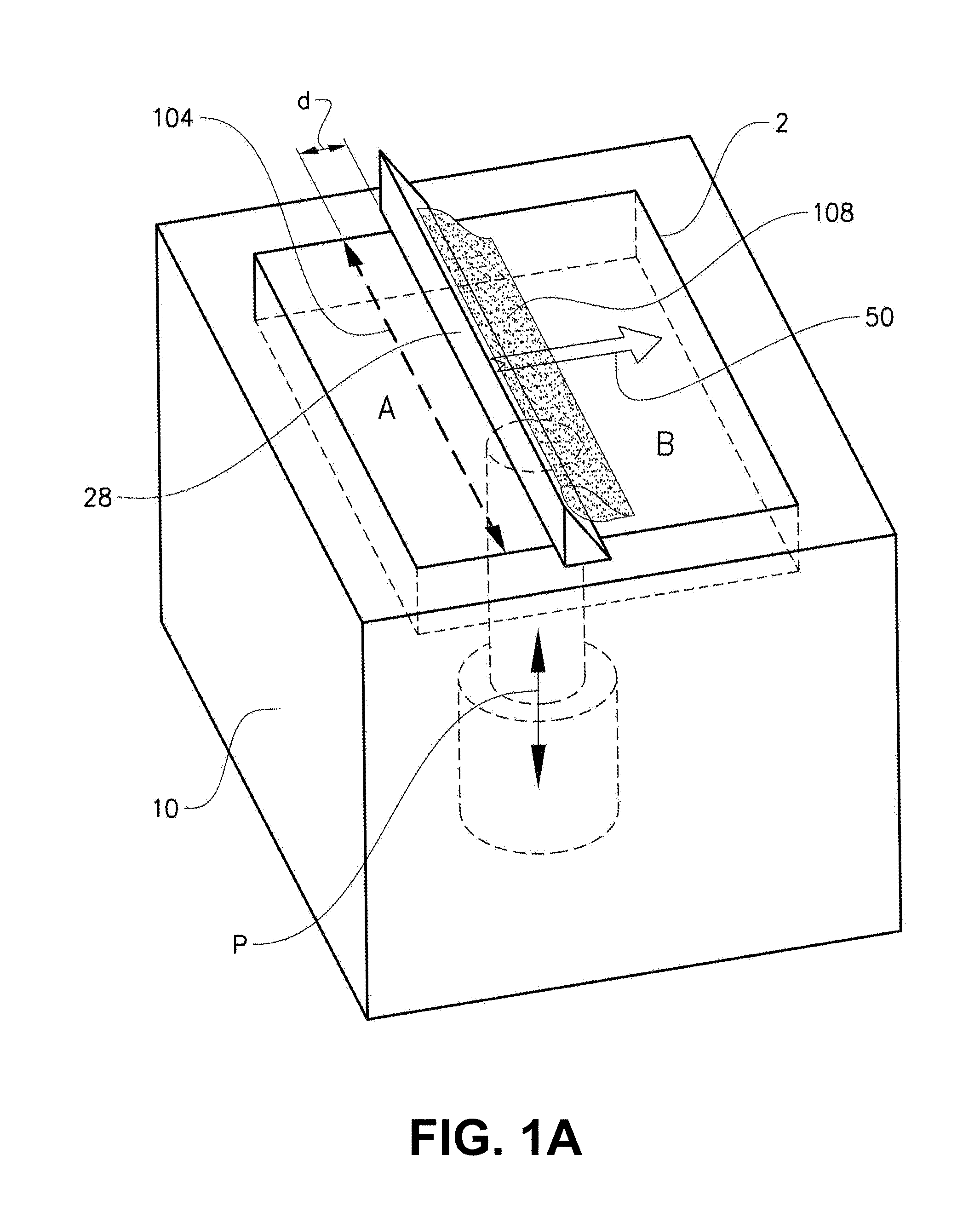
[0028] FIG. 1A depicts a perspective view of an example embodiment of a build tank, in which a first example embodiment of an inventive heating concept may be implemented while building a three-dimensional article;
[0029] FIG. 1B depicts a perspective view of an example embodiment of a build tank, in which a second example embodiment of an inventive heating concept may be implemented while building a three-dimensional article;
[0030] FIG. 1C depicts a perspective view of an example embodiment of a build tank, in which a third example embodiment of an inventive heating concept may be implemented while building a three-dimensional article;
[0031] FIG. 2 depicts, in a schematic view, an apparatus for producing a three dimensional product according to prior art;
[0032] FIG. 3 is a block diagram of an exemplary system 1020 according to various embodiments;
[0033] FIG. 4A is a schematic block diagram of a server 1200 according to various embodiments; and
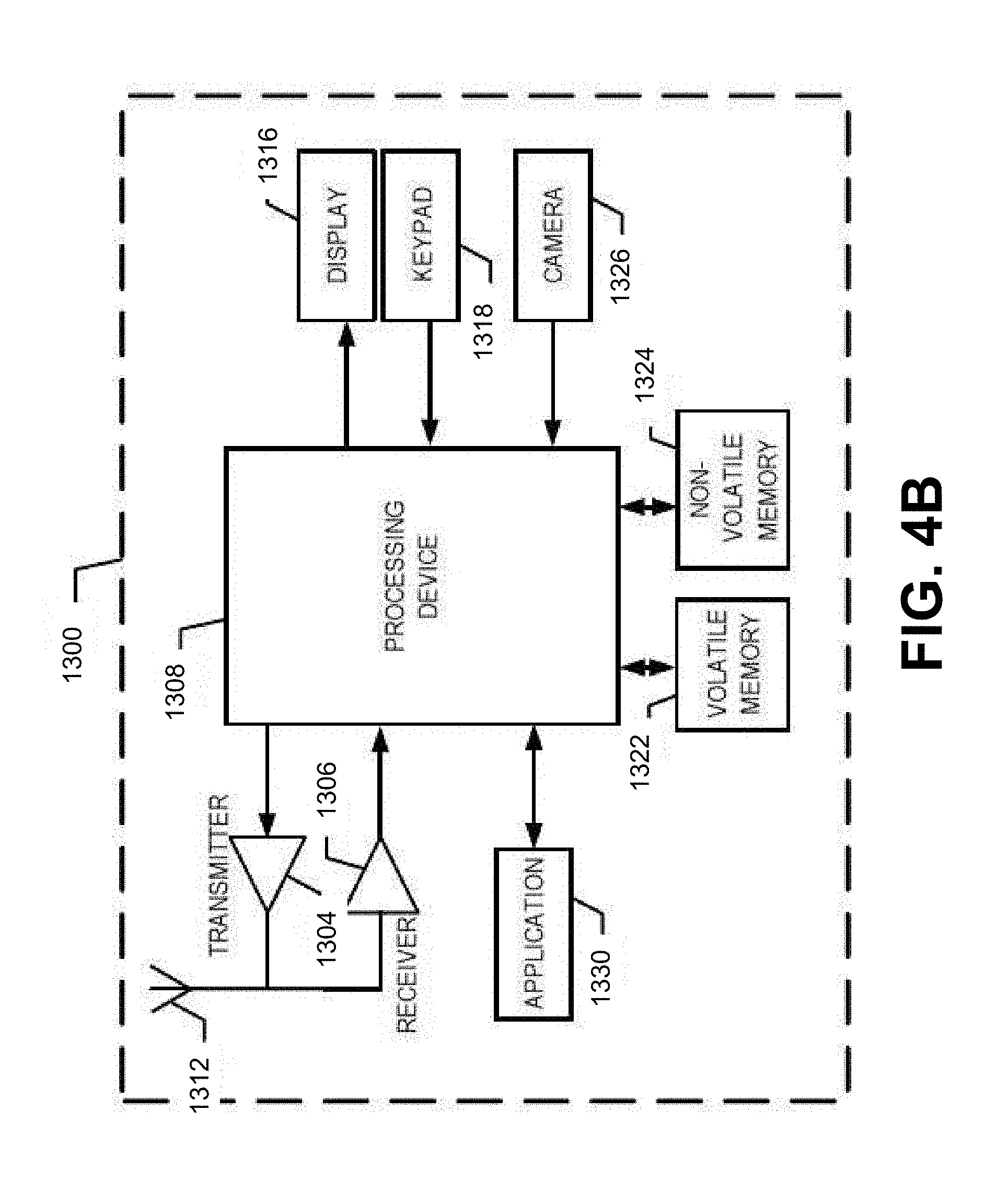
[0034] FIG. 4B is a schematic block diagram of an exemplary mobile device 1300 according to various embodiments.
DETAILED DESCRIPTION OF VARIOUS EMBODIMENTS
[0035] Various embodiments of the present invention will now be described more fully hereinafter with reference to the accompanying drawings, in which some, but not all embodiments of the invention are shown. Indeed, embodiments of the invention may be embodied in many different forms and should not be construed as limited to the embodiments set forth herein. Rather, these embodiments are provided so that this disclosure will satisfy applicable legal requirements. Unless otherwise defined, all technical and scientific terms used herein have the same meaning as commonly known and understood by one of ordinary skill in the art to which the invention relates. The term "or" is used herein in both the alternative and conjunctive sense, unless otherwise indicated. Like numbers refer to like elements throughout.
[0036] Still further, to facilitate the understanding of this invention, a number of terms are defined below. Terms defined herein have meanings as commonly understood by a person of ordinary skill in the areas relevant to the present invention. Terms such as "a", "an" and "the" are not intended to refer to only a singular entity, but include the general class of which a specific example may be used for illustration. The terminology herein is used to describe specific embodiments of the invention, but their usage does not delimit the invention, except as outlined in the claims.
[0037] The term "three-dimensional structures" and the like as used herein refer generally to intended or actually fabricated three-dimensional configurations (e.g., of structural material or materials) that are intended to be used for a particular purpose. Such structures, etc. may, for example, be designed with the aid of a three-dimensional CAD system.
[0038] The term "electron beam" as used herein in various embodiments refers to any charged particle beam. The sources of charged particle beam can include an electron gun, a linear accelerator and so on.
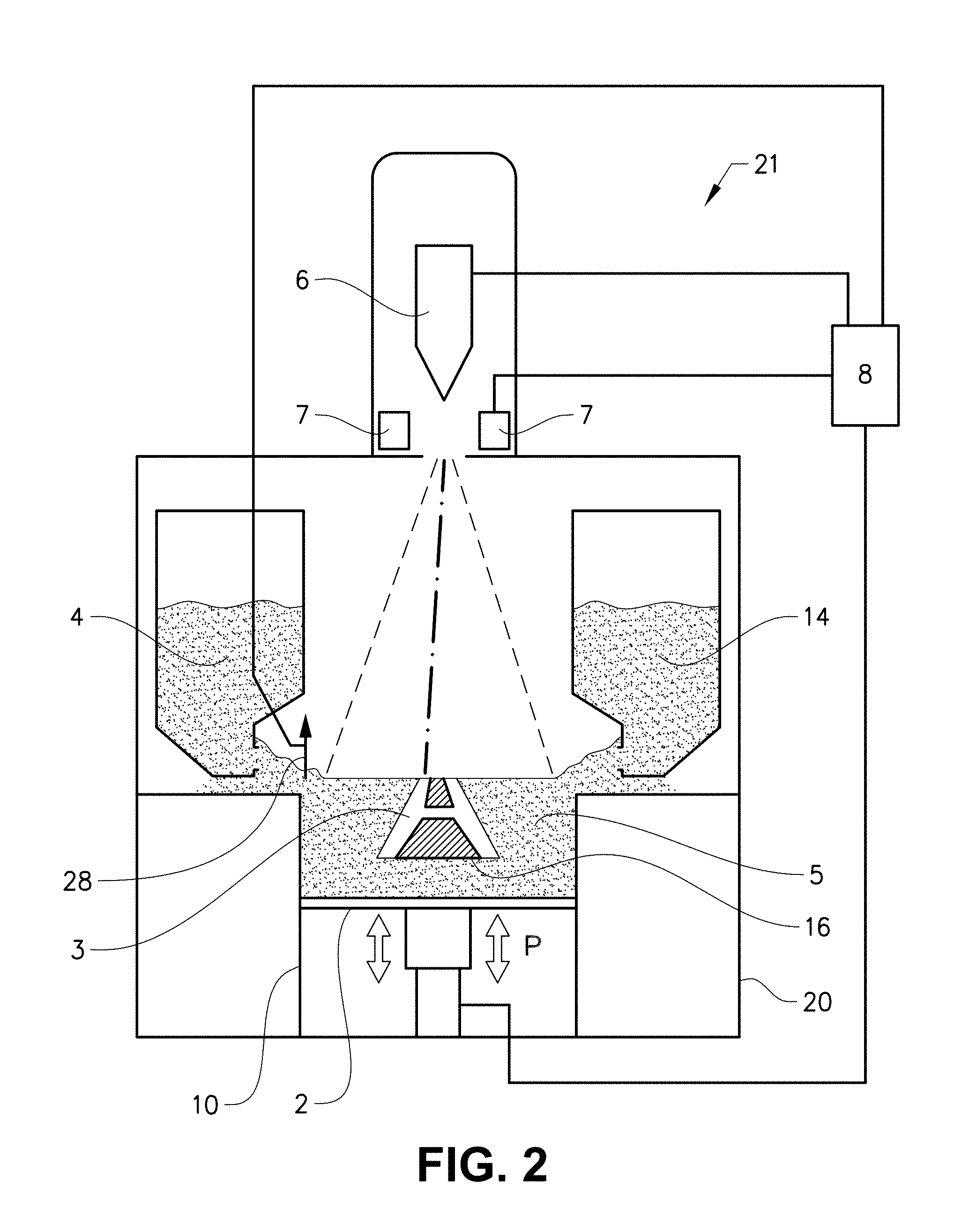
[0039] FIG. 2 depicts an embodiment of a freeform fabrication or additive manufacturing apparatus 21 in which the inventive method according to the present invention may be implemented.
[0040] The apparatus 21 comprising an electron beam gun 6; deflection coils 7; two powder hoppers 4, 14; a build platform 2; a build tank 10; a powder distributor 28; a powder bed 5; and a vacuum chamber 20.
[0041] The vacuum chamber 20 is capable of maintaining a vacuum environment by means of or via a vacuum system, which system may comprise a turbomolecular pump, a scroll pump, an ion pump and one or more valves which are well known to a skilled person in the art and therefore need no further explanation in this context. The vacuum system is controlled by a control unit 8.
[0042] The electron beam gun 6 is generating an electron beam which is used for melting or fusing together powder material provided on the build platform 2. At least a portion of the electron beam gun 6 may be provided in the vacuum chamber 20. The control unit 8 may be used for controlling and managing the electron beam emitted from the electron beam gun 6. At least one focusing coil (not shown), at least one deflection coil 7, an optional coil for astigmatic correction (not shown) and an electron beam power supply (not shown) may be electrically connected to the control unit 8. In an example embodiment of the invention the electron beam gun 6 generates a focusable electron beam with an accelerating voltage of about 15-60 kV and with a beam power in the range of 3-10 Kw. The pressure in the vacuum chamber may be 10.sup.-3 mbar or lower when building the three-dimensional article by fusing the powder layer by layer with the energy beam.
[0043] The powder hoppers 4, 14 comprise the powder material to be provided on the build platform 2 in the build tank 10. The powder material may for instance be pure metals or metal alloys such as titanium, titanium alloys, aluminum, aluminum alloys, stainless steel, Co-Cr alloys, nickel based superalloys, etc.
[0044] The powder distributor 28 is arranged to lay down a thin layer of the powder material on the build platform 2. During a work cycle the build platform 2 will be lowered successively in relation to a fixed point in the vacuum chamber. In order to make this movement possible, the build platform 2 is in one embodiment of the invention arranged movably in vertical direction, i.e., in the direction indicated by arrow P. This means that the build platform 2 starts in an initial position, in which a first powder material layer of necessary thickness has been laid down. Means for lowering the build platform 2 may for instance be through a servo engine equipped with a gear, adjusting screws, etc. The servo engine may be connected to the control unit 8.
[0045] An electron beam may be directed over the build platform 2 causing the first powder layer to fuse in selected locations to form a first cross section of the three-dimensional article 3. The beam is directed over the build platform 2 from instructions given by the control unit 8. In the control unit 8 instructions for how to control the electron beam for each layer of the three-dimensional article is stored. The first layer of the three dimensional article 3 may be built on the build platform 2, which may be removable, in the powder bed 5 or on an optional start plate 16. The start plate 16 may be arranged directly on the build platform 2 or on top of a powder bed 5 which is provided on the build platform 2.
[0046] After a first layer is finished, i.e., the fusion of powder material for making a first layer of the three-dimensional article, a second powder layer is provided on the build platform 2. The second powder layer is in certain embodiments preferably distributed according to the same manner as the previous layer. However, there might be alternative methods in the same additive manufacturing machine for distributing powder onto the work table. For instance, a first layer may be provided via or by means of a first powder distributor 28, a second layer may be provided by another powder distributor. The design of the powder distributor is automatically changed according to instructions from the control unit 8. A powder distributor 28 in the form of a single rake system, i.e., where one rake is catching powder fallen down from both a left powder hopper 4 and a right powder hopper 14, the rake as such can change design.
[0047] After having distributed the second powder layer on the build platform, the energy beam is directed over the work table causing the second powder layer to fuse in selected locations to form a second cross section of the three-dimensional article. Fused portions in the second layer may be bonded to fused portions of the first layer. The fused portions in the first and second layer may be melted together by melting not only the powder in the uppermost layer but also remelting at least a fraction of a thickness of a layer directly below the uppermost layer.
[0048] In the case where an electron beam is used, it is necessary to consider the charge distribution that is created in the powder as the electrons hit the powder bed 5. The charge distribution density depends on the following parameters: beam current, electron velocity (which is given by the accelerating voltage), beam scanning velocity, powder material and electrical conductivity of the powder, i.e., mainly the electrical conductivity between the powder grains. The latter is in turn a function of several parameters, such as temperature, degree of sintering and powder grain size/size distribution.
[0049] Thus, for a given powder, i.e., a powder of a certain material with a certain grain size distribution, and a given accelerating voltage, it is possible, by varying the beam current (and thus the beam power) and the beam scanning velocity, to affect the charge distribution.
[0050] By varying these parameters in a controlled way, the electrical conductivity of the powder can gradually be increased by increasing the temperature of the powder. A powder that has a high temperature obtains a considerably higher conductivity which results in a lower density of the charge distribution since the charges quickly can diffuse over a large region. This effect is enhanced if the powder is allowed to be slightly sintered during a pre-heating process. When the conductivity has become sufficiently high, the powder can be fused together, i.e., melted or fully sintered, with predetermined values of the beam current and beam scanning velocity.
[0051] In another embodiment a laser beam may be used for melting or fusing the powder material. In such case tiltable mirrors may be used in the beam path in order to deflect the laser beam to a predetermined position.
[0052] FIG. 1A depicts a perspective view of an example embodiment of a build tank 10 in which a first example embodiment of an inventive heating concept may be implemented while building a three-dimensional article. The build tank comprises a build platform 2, which is movable up and down according to the arrow P, and a powder distributor 28. The build platform 2 inside the build tank 10 is depicted to have a rectangular shape, obviously the build tank may have any desirable shape. In FIG. 1A the powder distributor 28 is applying a new powder layer on a previously partly fused powder layer.
[0053] In FIG. 1A there are essentially three different regions when applying a new powder layer. A first region, which is denoted by A, is the top surface of the new powder layer. A second region, which is denoted by B, is the top surface of the previous partially fused powder layer. A third region, which is denoted by 108, is the powder to be distributed on top of the second region B.
[0054] The new powder layer in the first region A is heated according to the invention by an energy beam while the powder layer is applied on top of the previous partially fused powder layer. The application of a full powder layer takes time. During the time the temperature of the powder layer may decrease under a predetermined minimum temperature. This may require a preheating of the powder layer before the fusion takes place. Instead of waiting until the full powder layer has been applied on top of the previous partially fused powder layer, the heating of the newly applied powder layer may be done during the powder distribution. In FIG. 1A an energy beam is heating the new powder layer in region A, this is denoted by a line 104. When heating of the powder layer is performed during the application of a powder layer, any additional heating required when the powder layer has been completed may be minimized or completely eliminated for achieving a predetermined temperature interval of the new layer to be fused. The heating may be performed by the same energy source as is later used for fusing the powder layer in selected locations. In another embodiment a separate heating source is used for heating and another source is used for fusing the powder material. The heating source may be a laser source, electron beam source, IR source or a resistive heating source. The source for fusing the powder material may be a laser source and/or an electron beam source.
[0055] In FIG. 1A the heating, denoted by line 104, of the newly applied powder layer is set to be at a predetermined distance d from the powder distributor 28. The distance d is a safety distance of a heating spot from the powder distributor. If the heating of the powder material is too close to the powder distributor the powder distributor itself may be heated to an undesirable high temperature which may cause the powder material to stick at the powder distributor. In FIG. 1A the heating is denoted to be a straight line 104. However, any means of heating the first region A may be used, such as meander formed heating lines or randomly distributed scan lines of a predetermined length. In an example embodiment a temperature measurement of the newly applied powder layer in the first region A may be performed and the heating may be prioritized at the regions where the temperature is lowest. The temperature measurement may be done by a temperature sensitive camera, e.g., a IR camera. The IR picture from the IR camera is transformed into a 2-dimensional temperature map of the first region A. The heating source may be instructed by a control unit to apply a predetermined heating powder at predetermined locations in order to achieve as homogenous surface temperature as possible of the new powder layer in the first region A. In an example embodiment the temperature to which the new powder layer is elevated to is sufficient for the new powder layer to sinter, i.e., a sufficient temperature for bonding powder particles together in the new powder layer and/or bonding the new powder layer to the underlying layer, but not as high as to create a fusion of the powder particles.
[0056] When maintaining a predetermined temperature interval of the new powder layer the fusion process may be more predictable. If the temperature in which the new powder layer is maintained at is set to be in a temperature interval just below the melting point, the energy which is required for melting the new layer and also remelting a sufficient portion of the previous layer is more predictable. For this reason a more homogenous and predictable microstructure of the solidified portions of the three-dimensional article can be achieved.
[0057] The heating position of the new powder layer may be synchronized with the movement of the powder distributor 28 in order to keep track of the position of the powder distributor 28 and also keep track of the constantly increased area of the first region A as the powder application is going on. The powder distributor 28 is moving in a direction of the arrow 50 in FIG. 1A-1C.
[0058] In another embodiment a plurality of energy beams may be used for heating the first region A of the new powder layer. The plurality of beams may be of the same type, i.e., a plurality of laser beams or a plurality of electron beams. In another embodiment the plurality of energy beams may be of different types, i.e., one or several laser beams and one or several electron beams.
[0059] FIG. 1B depicts a perspective view of an example embodiment of a build tank 10 in which a second example embodiment of an inventive heating concept may be implemented while building a three-dimensional article.
[0060] The build tank comprises the same features as the build tank depicted in FIG. 1A. The heating concept is somewhat different to what is disclosed in connection with FIG. 1A. Here in FIG. 1B not only the newly applied powder layer in the first region A is heated by at least one energy beam as depicted in FIG. 1A by line 104, but also the second region B is heated by at least one energy beam denoted by 110.
[0061] The second region B may be heated to a predetermined temperature interval prior to applying the new powder layer and thereby enabling the new powder layer to self-sinter, i.e., the temperature interval may be sufficiently high for the powder particles in the new powder layer to be slightly bonded to the underlying layer and/or slightly bonded to each other, but sufficiently low for prohibiting the powder particles to be fused/melted.
[0062] The heating of the second region B with at least one energy beam may be performed at a security distance denoted by "e" in FIG. 1B from the third region 108 comprising the powder to be distributed. The security distance e may be set for prohibiting the powder in region 108 to be distributed to self-sinter before it is applied on top of the previous partially fused powder layer.
[0063] In an example embodiment the first region A may be heated with a first energy beam source and the second region B with a second energy beam source. The first and second energy beam sources may be of the same type or different type, i.e., the first energy beam source may be a laser beam source and the second energy beam source may be an electron beam source. In another embodiment the first and second energy beam sources may be of the same type, i.e., laser beam source or electron beam source.
[0064] In still another example embodiment the first region may be heated with a plurality of energy beam sources and the second region may be heated with a plurality of energy beam sources.
[0065] In still another example embodiment one and the same energy beam source may be used for heating the first and the second region, i.e., a single energy beam source is used for heating on both sides of the powder distributor 28. In this embodiment it may be preferable to switch off the energy beam source while passing the powder distributor for prohibiting unnecessary temperature increase of the powder distributor and the not yet distributed powder in front of the powder distributor 28. In another embodiment, the energy beam may be greatly defocused while passing the powder distributor for eliminating or at least reduce the impact of the energy beam onto the powder distributor and the non applied powder. When the energy beam is in a desired position for heating, the energy beam may be focused to a predetermined level for heating the first or second region, A and B respectively, to a desired level. When using a single energy beam for heating the first and second region the position of the energy beam may be synchronized with the position of the powder distributor 28 for keeping track of the position of the powder distributor and for allowing the energy beam to know the size of the first and second region which is constantly changing while the powder distributor is moving forward.
[0066] As in FIG. 1A, in FIG. 1B the heating is denoted to be straight lines 104, 110. However, any means of heating the regions A,B may be used, such as meander formed heating lines or randomly distributed scan lines of a predetermined length.
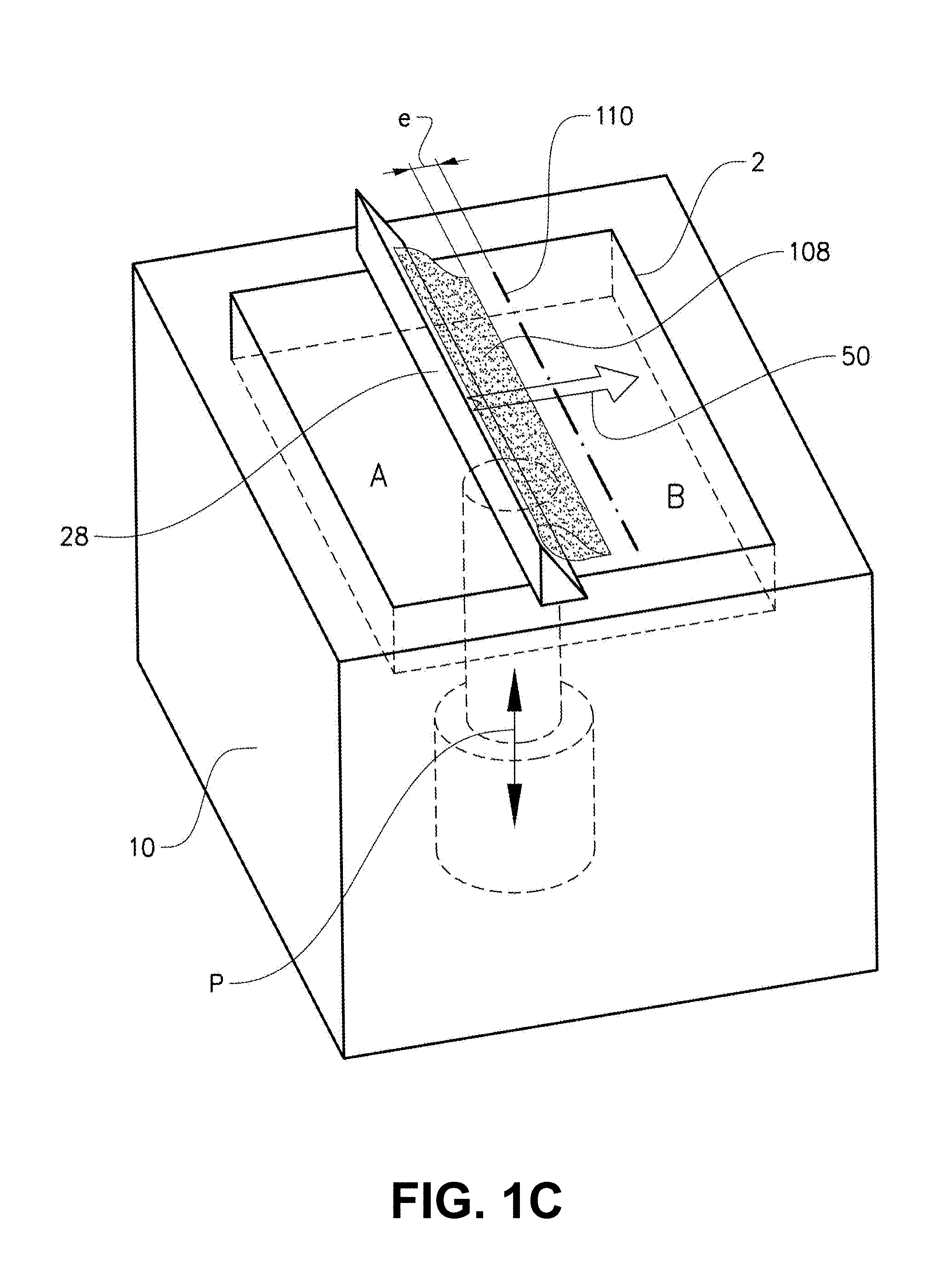
[0067] FIG. 1C depicts a perspective view of an example embodiment of a build tank 10 in which a third example embodiment of an inventive heating concept may be implemented while building a three-dimensional article.
[0068] In the third example embodiment of the heating concept according to the present invention the heating is only performed in the second region B where the powder has not yet been applied. As in FIG. 1B there is a safety distance e between the powder to be distributed and the line of heating 110 the second region. The safety distance is used for the same reason as already has been explained in relation to FIG. 1B. The heating of the second region may be to a sufficiently high predetermined temperature interval allowing the new powder layer to self-sinter when it is applied on top of the heated surface. In another embodiment the powder is not allowed to self-sinter, i.e., the temperature interval is chosen to be lower than the self-sintering temperature for the type of powder material to be distributed. The temperature is not allowed to be so high so that the powder particles will be fused. The fusion of the particles will take place in a following step when the new powder layer is completed over the previous partially fused layer and its temperature is falling within a predetermined temperature interval.
[0069] In an example embodiment the energy beam for fusing the powder layer may be the same energy beam source which is used for heating at least one of the first or second regions.
[0070] As in FIG. 1B, in FIG. 1C the heating is denoted to be a straight line 110. However, any means of heating the region B may be used, such as meander formed heating lines or randomly distributed scan lines of a predetermined length.
[0071] In another aspect of the invention it is provided a program element configured and arranged when executed on a computer to implement a method for forming a three-dimensional article through successively depositing individual layers of powder material that are fused together so as to form the article. The program may be installed in a computer readable storage medium. The computer readable storage medium may be the control unit 8 described elsewhere herein or another separate and distinct control unit, or another comparable device, as desirable and well-known. The computer readable storage medium and the program element, which may comprise computer-readable program code portions embodied therein, may further be contained within a non-transitory computer program product. Further details in this regard are provided elsewhere herein.
[0072] As mentioned, various embodiments of the present invention may be implemented in various ways, including as non-transitory computer program products. A computer program product may include a non-transitory computer-readable storage medium storing applications, programs, program modules, scripts, source code, program code, object code, byte code, compiled code, interpreted code, machine code, executable instructions, and/or the like (also referred to herein as executable instructions, instructions for execution, program code, and/or similar terms used herein interchangeably). Such non-transitory computer-readable storage media include all computer-readable media (including volatile and non-volatile media).
[0073] In one embodiment, a non-volatile computer-readable storage medium may include a floppy disk, flexible disk, hard disk, solid-state storage (SSS) (e.g., a solid state drive (SSD), solid state card (SSC), solid state module (SSM)), enterprise flash drive, magnetic tape, or any other non-transitory magnetic medium, and/or the like. A non-volatile computer-readable storage medium may also include a punch card, paper tape, optical mark sheet (or any other physical medium with patterns of holes or other optically recognizable indicia), compact disc read only memory (CD-ROM), compact disc compact disc-rewritable (CD-RW), digital versatile disc (DVD), Blu-ray disc (BD), any other non-transitory optical medium, and/or the like. Such a non-volatile computer-readable storage medium may also include read-only memory (ROM), programmable read-only memory (PROM), erasable programmable read-only memory (EPROM), electrically erasable programmable read-only memory (EEPROM), flash memory (e.g., Serial, NAND, NOR, and/or the like), multimedia memory cards (MMC), secure digital (SD) memory cards, SmartMedia cards, CompactFlash (CF) cards, Memory Sticks, and/or the like. Further, a non-volatile computer-readable storage medium may also include conductive-bridging random access memory (CBRAM), phase-change random access memory (PRAM), ferroelectric random-access memory (FeRAM), non-volatile random-access memory (NVRAM), magnetoresistive random-access memory (MRAM), resistive random-access memory (RRAM), Silicon-Oxide-Nitride-Oxide-Silicon memory (SONOS), floating junction gate random access memory (FJG RAM), Millipede memory, racetrack memory, and/or the like.
[0074] In one embodiment, a volatile computer-readable storage medium may include random access memory (RAM), dynamic random access memory (DRAM), static random access memory (SRAM), fast page mode dynamic random access memory (FPM DRAM), extended data-out dynamic random access memory (EDO DRAM), synchronous dynamic random access memory (SDRAM), double data rate synchronous dynamic random access memory (DDR SDRAM), double data rate type two synchronous dynamic random access memory (DDR2 SDRAM), double data rate type three synchronous dynamic random access memory (DDR3 SDRAM), Rambus dynamic random access memory (RDRAM), Twin Transistor RAM (TTRAM), Thyristor RAM (T-RAM), Zero-capacitor (Z-RAM), Rambus in-line memory module (RIMM), dual in-line memory module (DIMM), single in-line memory module (SIMM), video random access memory VRAM, cache memory (including various levels), flash memory, register memory, and/or the like. It will be appreciated that where embodiments are described to use a computer-readable storage medium, other types of computer-readable storage media may be substituted for or used in addition to the computer-readable storage media described above.
[0075] As should be appreciated, various embodiments of the present invention may also be implemented as methods, apparatus, systems, computing devices, computing entities, and/or the like, as have been described elsewhere herein. As such, embodiments of the present invention may take the form of an apparatus, system, computing device, computing entity, and/or the like executing instructions stored on a computer-readable storage medium to perform certain steps or operations. However, embodiments of the present invention may also take the form of an entirely hardware embodiment performing certain steps or operations.
[0076] Various embodiments are described below with reference to block diagrams and flowchart illustrations of apparatuses, methods, systems, and computer program products. It should be understood that each block of any of the block diagrams and flowchart illustrations, respectively, may be implemented in part by computer program instructions, e.g., as logical steps or operations executing on a processor in a computing system. These computer program instructions may be loaded onto a computer, such as a special purpose computer or other programmable data processing apparatus to produce a specifically-configured machine, such that the instructions which execute on the computer or other programmable data processing apparatus implement the functions specified in the flowchart block or blocks.
[0077] These computer program instructions may also be stored in a computer-readable memory that can direct a computer or other programmable data processing apparatus to function in a particular manner, such that the instructions stored in the computer-readable memory produce an article of manufacture including computer-readable instructions for implementing the functionality specified in the flowchart block or blocks. The computer program instructions may also be loaded onto a computer or other programmable data processing apparatus to cause a series of operational steps to be performed on the computer or other programmable apparatus to produce a computer-implemented process such that the instructions that execute on the computer or other programmable apparatus provide operations for implementing the functions specified in the flowchart block or blocks.
[0078] Accordingly, blocks of the block diagrams and flowchart illustrations support various combinations for performing the specified functions, combinations of operations for performing the specified functions and program instructions for performing the specified functions. It should also be understood that each block of the block diagrams and flowchart illustrations, and combinations of blocks in the block diagrams and flowchart illustrations, could be implemented by special purpose hardware-based computer systems that perform the specified functions or operations, or combinations of special purpose hardware and computer instructions.
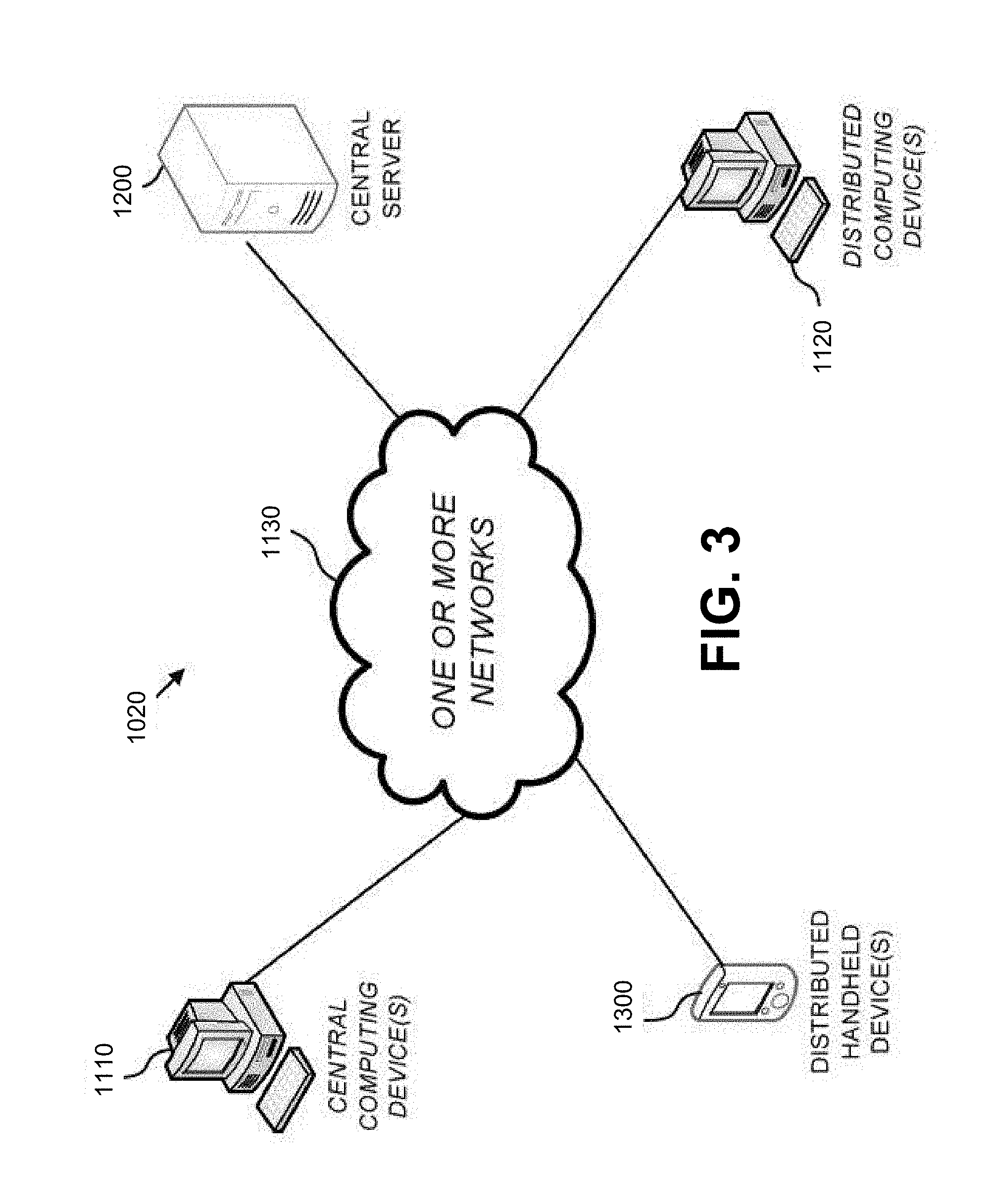
[0079] FIG. 3 is a block diagram of an exemplary system 1020 that can be used in conjunction with various embodiments of the present invention. In at least the illustrated embodiment, the system 1020 may include one or more central computing devices 1110, one or more distributed computing devices 1120, and one or more distributed handheld or mobile devices 1300, all configured in communication with a central server 1200 (or control unit) via one or more networks 1130. While FIG. 3 illustrates the various system entities as separate, standalone entities, the various embodiments are not limited to this particular architecture.
[0080] According to various embodiments of the present invention, the one or more networks 1130 may be capable of supporting communication in accordance with any one or more of a number of second-generation (2G), 2.5G, third-generation (3G), and/or fourth-generation (4G) mobile communication protocols, or the like. More particularly, the one or more networks 1130 may be capable of supporting communication in accordance with 2G wireless communication protocols IS-136 (TDMA), GSM, and IS-95 (CDMA). Also, for example, the one or more networks 1130 may be capable of supporting communication in accordance with 2.5G wireless communication protocols GPRS, Enhanced Data GSM Environment (EDGE), or the like. In addition, for example, the one or more networks 1130 may be capable of supporting communication in accordance with 3G wireless communication protocols such as Universal Mobile Telephone System (UMTS) network employing Wideband Code Division Multiple Access (WCDMA) radio access technology. Some narrow-band AMPS (NAMPS), as well as TACS, network(s) may also benefit from embodiments of the present invention, as should dual or higher mode mobile stations (e.g., digital/analog or TDMA/CDMA/analog phones). As yet another example, each of the components of the system 5 may be configured to communicate with one another in accordance with techniques such as, for example, radio frequency (RF), Bluetooth.TM., infrared (IrDA), or any of a number of different wired or wireless networking techniques, including a wired or wireless Personal Area Network ("PAN"), Local Area Network ("LAN"), Metropolitan Area Network ("MAN"), Wide Area Network ("WAN"), or the like.
[0081] Although the device(s) 1110-1300 are illustrated in FIG. 3 as communicating with one another over the same network 1130, these devices may likewise communicate over multiple, separate networks.
[0082] According to one embodiment, in addition to receiving data from the server 1200, the distributed devices 1110, 1120, and/or 1300 may be further configured to collect and transmit data on their own. In various embodiments, the devices 1110, 1120, and/or 1300 may be capable of receiving data via one or more input units or devices, such as a keypad, touchpad, barcode scanner, radio frequency identification (RFID) reader, interface card (e.g., modem, etc.) or receiver. The devices 1110, 1120, and/or 1300 may further be capable of storing data to one or more volatile or non-volatile memory modules, and outputting the data via one or more output units or devices, for example, by displaying data to the user operating the device, or by transmitting data, for example over the one or more networks 1130.
[0083] In various embodiments, the server 1200 includes various systems for performing one or more functions in accordance with various embodiments of the present invention, including those more particularly shown and described herein. It should be understood, however, that the server 1200 might include a variety of alternative devices for performing one or more like functions, without departing from the spirit and scope of the present invention. For example, at least a portion of the server 1200, in certain embodiments, may be located on the distributed device(s) 1110, 1120, and/or the handheld or mobile device(s) 1300, as may be desirable for particular applications. As will be described in further detail below, in at least one embodiment, the handheld or mobile device(s) 1300 may contain one or more mobile applications 1330 which may be configured so as to provide a user interface for communication with the server 1200, all as will be likewise described in further detail below.
[0084] FIG. 4A is a schematic diagram of the server 1200 according to various embodiments. The server 1200 includes a processor 1230 that communicates with other elements within the server via a system interface or bus 1235. Also included in the server 1200 is a display/input device 1250 for receiving and displaying data. This display/input device 1250 may be, for example, a keyboard or pointing device that is used in combination with a monitor. The server 1200 further includes memory 1220, which preferably includes both read only memory (ROM) 1226 and random access memory (RAM) 1222. The server's ROM 1226 is used to store a basic input/output system 1224 (BIOS), containing the basic routines that help to transfer information between elements within the server 1200. Various ROM and RAM configurations have been previously described herein.
[0085] In addition, the server 1200 includes at least one storage device or program storage 210, such as a hard disk drive, a floppy disk drive, a CD Rom drive, or optical disk drive, for storing information on various computer-readable media, such as a hard disk, a removable magnetic disk, or a CD-ROM disk. As will be appreciated by one of ordinary skill in the art, each of these storage devices 1210 are connected to the system bus 1235 by an appropriate interface. The storage devices 1210 and their associated computer-readable media provide nonvolatile storage for a personal computer. As will be appreciated by one of ordinary skill in the art, the computer-readable media described above could be replaced by any other type of computer-readable media known in the art. Such media include, for example, magnetic cassettes, flash memory cards, digital video disks, and Bernoulli cartridges.
[0086] Although not shown, according to an embodiment, the storage device 1210 and/or memory of the server 1200 may further provide the functions of a data storage device, which may store historical and/or current delivery data and delivery conditions that may be accessed by the server 1200. In this regard, the storage device 1210 may comprise one or more databases. The term "database" refers to a structured collection of records or data that is stored in a computer system, such as via a relational database, hierarchical database, or network database and as such, should not be construed in a limiting fashion.
[0087] A number of program modules (e.g., exemplary modules 1400-1700) comprising, for example, one or more computer-readable program code portions executable by the processor 1230, may be stored by the various storage devices 1210 and within RAM 1222. Such program modules may also include an operating system 1280. In these and other embodiments, the various modules 1400, 1500, 1600, 1700 control certain aspects of the operation of the server 1200 with the assistance of the processor 1230 and operating system 1280. In still other embodiments, it should be understood that one or more additional and/or alternative modules may also be provided, without departing from the scope and nature of the present invention.
[0088] In various embodiments, the program modules 1400, 1500, 1600, 1700 are executed by the server 1200 and are configured to generate one or more graphical user interfaces, reports, instructions, and/or notifications/alerts, all accessible and/or transmittable to various users of the system 1020. In certain embodiments, the user interfaces, reports, instructions, and/or notifications/alerts may be accessible via one or more networks 1130, which may include the Internet or other feasible communications network, as previously discussed.
[0089] In various embodiments, it should also be understood that one or more of the modules 1400, 1500, 1600, 1700 may be alternatively and/or additionally (e.g., in duplicate) stored locally on one or more of the devices 1110, 1120, and/or 1300 and may be executed by one or more processors of the same. According to various embodiments, the modules 1400, 1500, 1600, 1700 may send data to, receive data from, and utilize data contained in one or more databases, which may be comprised of one or more separate, linked and/or networked databases.
[0090] Also located within the server 1200 is a network interface 1260 for interfacing and communicating with other elements of the one or more networks 1130. It will be appreciated by one of ordinary skill in the art that one or more of the server 1200 components may be located geographically remotely from other server components. Furthermore, one or more of the server 1200 components may be combined, and/or additional components performing functions described herein may also be included in the server.
[0091] While the foregoing describes a single processor 1230, as one of ordinary skill in the art will recognize, the server 1200 may comprise multiple processors operating in conjunction with one another to perform the functionality described herein. In addition to the memory 1220, the processor 1230 can also be connected to at least one interface or other means for displaying, transmitting and/or receiving data, content or the like. In this regard, the interface(s) can include at least one communication interface or other means for transmitting and/or receiving data, content or the like, as well as at least one user interface that can include a display and/or a user input interface, as will be described in further detail below. The user input interface, in turn, can comprise any of a number of devices allowing the entity to receive data from a user, such as a keypad, a touch display, a joystick or other input device.
[0092] Still further, while reference is made to the "server" 1200, as one of ordinary skill in the art will recognize, embodiments of the present invention are not limited to traditionally defined server architectures. Still further, the system of embodiments of the present invention is not limited to a single server, or similar network entity or mainframe computer system. Other similar architectures including one or more network entities operating in conjunction with one another to provide the functionality described herein may likewise be used without departing from the spirit and scope of embodiments of the present invention. For example, a mesh network of two or more personal computers (PCs), similar electronic devices, or handheld portable devices, collaborating with one another to provide the functionality described herein in association with the server 1200 may likewise be used without departing from the spirit and scope of embodiments of the present invention.
[0093] According to various embodiments, many individual steps of a process may or may not be carried out utilizing the computer systems and/or servers described herein, and the degree of computer implementation may vary, as may be desirable and/or beneficial for one or more particular applications.
[0094] FIG. 4B provides an illustrative schematic representative of a mobile device 1300 that can be used in conjunction with various embodiments of the present invention. Mobile devices 1300 can be operated by various parties. As shown in FIG. 4B, a mobile device 1300 may include an antenna 1312, a transmitter 1304 (e.g., radio), a receiver 1306 (e.g., radio), and a processing element 1308 that provides signals to and receives signals from the transmitter 1304 and receiver 1306, respectively.
[0095] The signals provided to and received from the transmitter 1304 and the receiver 1306, respectively, may include signaling data in accordance with an air interface standard of applicable wireless systems to communicate with various entities, such as the server 1200, the distributed devices 1110, 1120, and/or the like. In this regard, the mobile device 1300 may be capable of operating with one or more air interface standards, communication protocols, modulation types, and access types. More particularly, the mobile device 1300 may operate in accordance with any of a number of wireless communication standards and protocols. In a particular embodiment, the mobile device 1300 may operate in accordance with multiple wireless communication standards and protocols, such as GPRS, UMTS, CDMA2000, 1xRTT, WCDMA, TD-SCDMA, LTE, E-UTRAN, EVDO, HSPA, HSDPA, Wi-Fi, WiMAX, UWB, IR protocols, Bluetooth protocols, USB protocols, and/or any other wireless protocol.
[0096] Via these communication standards and protocols, the mobile device 1300 may according to various embodiments communicate with various other entities using concepts such as Unstructured Supplementary Service data (USSD), Short Message Service (SMS), Multimedia Messaging Service (MMS), Dual-Tone Multi-Frequency Signaling (DTMF), and/or Subscriber Identity Module Dialer (SIM dialer). The mobile device 1300 can also download changes, add-ons, and updates, for instance, to its firmware, software (e.g., including executable instructions, applications, program modules), and operating system.
[0097] According to one embodiment, the mobile device 1300 may include a location determining device and/or functionality. For example, the mobile device 1300 may include a GPS module adapted to acquire, for example, latitude, longitude, altitude, geocode, course, and/or speed data. In one embodiment, the GPS module acquires data, sometimes known as ephemeris data, by identifying the number of satellites in view and the relative positions of those satellites.
[0098] The mobile device 1300 may also comprise a user interface (that can include a display 1316 coupled to a processing element 1308) and/or a user input interface (coupled to a processing element 308). The user input interface can comprise any of a number of devices allowing the mobile device 1300 to receive data, such as a keypad 1318 (hard or soft), a touch display, voice or motion interfaces, or other input device. In embodiments including a keypad 1318, the keypad can include (or cause display of) the conventional numeric (0-9) and related keys (#, *), and other keys used for operating the mobile device 1300 and may include a full set of alphabetic keys or set of keys that may be activated to provide a full set of alphanumeric keys. In addition to providing input, the user input interface can be used, for example, to activate or deactivate certain functions, such as screen savers and/or sleep modes.
[0099] The mobile device 1300 can also include volatile storage or memory 1322 and/or non-volatile storage or memory 1324, which can be embedded and/or may be removable. For example, the non-volatile memory may be ROM, PROM, EPROM, EEPROM, flash memory, MMCs, SD memory cards, Memory Sticks, CBRAM, PRAM, FeRAM, RRAM, SONOS, racetrack memory, and/or the like. The volatile memory may be RAM, DRAM, SRAM, FPM DRAM, EDO DRAM, SDRAM, DDR SDRAM, DDR2 SDRAM, DDR3 SDRAM, RDRAM, RIMM, DIMM, SIMM, VRAM, cache memory, register memory, and/or the like. The volatile and non-volatile storage or memory can store databases, database instances, database mapping systems, data, applications, programs, program modules, scripts, source code, object code, byte code, compiled code, interpreted code, machine code, executable instructions, and/or the like to implement the functions of the mobile device 1300.
[0100] The mobile device 1300 may also include one or more of a camera 1326 and a mobile application 1330. The camera 1326 may be configured according to various embodiments as an additional and/or alternative data collection feature, whereby one or more items may be read, stored, and/or transmitted by the mobile device 1300 via the camera. The mobile application 1330 may further provide a feature via which various tasks may be performed with the mobile device 1300. Various configurations may be provided, as may be desirable for one or more users of the mobile device 1300 and the system 1020 as a whole.
[0101] The invention is not limited to the above-described embodiments and many modifications are possible within the scope of the following claims. Such modifications may, for example, involve using a different source of energy beam than the exemplified electron beam such as a laser beam. Other materials than metallic powder may be used, such as powder of polymers or powder of ceramics.
* * * * *
D00000
D00001
D00002
D00003
D00004
D00005
D00006
D00007
XML
uspto.report is an independent third-party trademark research tool that is not affiliated, endorsed, or sponsored by the United States Patent and Trademark Office (USPTO) or any other governmental organization. The information provided by uspto.report is based on publicly available data at the time of writing and is intended for informational purposes only.
While we strive to provide accurate and up-to-date information, we do not guarantee the accuracy, completeness, reliability, or suitability of the information displayed on this site. The use of this site is at your own risk. Any reliance you place on such information is therefore strictly at your own risk.
All official trademark data, including owner information, should be verified by visiting the official USPTO website at www.uspto.gov. This site is not intended to replace professional legal advice and should not be used as a substitute for consulting with a legal professional who is knowledgeable about trademark law.