Method For Producing H-shaped Steel
YAMASHITA; Hiroshi ; et al.
U.S. patent application number 16/082334 was filed with the patent office on 2019-01-24 for method for producing h-shaped steel. This patent application is currently assigned to NIPPON STEEL & SUMITOMO METAL CORPORATION. The applicant listed for this patent is NIPPON STEEL & SUMITOMO METAL CORPORATION. Invention is credited to Ryo HASHIMOTO, Hiroshi YAMASHITA.
| Application Number | 20190022719 16/082334 |
| Document ID | / |
| Family ID | 60160496 |
| Filed Date | 2019-01-24 |


| United States Patent Application | 20190022719 |
| Kind Code | A1 |
| YAMASHITA; Hiroshi ; et al. | January 24, 2019 |
METHOD FOR PRODUCING H-SHAPED STEEL
Abstract
To efficiently and stably produce an H-shaped steel product with a flange width larger than a conventional flange width by creating deep splits on end surfaces of a material such as a slab using projections in acute-angle tip shapes and sequentially bending flange portions formed by the splits to thereby suppress occurrence of shape defects in a material to be rolled and reduce growth of a crop portion. A first caliber and a second caliber of a plurality of calibers are formed with projections configured to create splits vertically with respect to a width direction of the material to be rolled to form divided parts at end portions of the material to be rolled; a third caliber and subsequent calibers excluding a final caliber of the plurality of calibers are formed with projections configured to come into contact with the splits to sequentially bend the divided parts formed; and in at least one pass or more of rolling and shaping in the plurality of calibers, the rolling and shaping is performed with a rolling roll gap for a predetermined section at a rear end portion in a rolling longitudinal direction of the material to be rolled expanded as compared with a rolling roll gap for other than the predetermined section.
| Inventors: | YAMASHITA; Hiroshi; (Tokyo, JP) ; HASHIMOTO; Ryo; (Tokyo, JP) | ||||||||||
| Applicant: |
|
||||||||||
|---|---|---|---|---|---|---|---|---|---|---|---|
| Assignee: | NIPPON STEEL & SUMITOMO METAL
CORPORATION Tokyo JP |
||||||||||
| Family ID: | 60160496 | ||||||||||
| Appl. No.: | 16/082334 | ||||||||||
| Filed: | April 24, 2017 | ||||||||||
| PCT Filed: | April 24, 2017 | ||||||||||
| PCT NO: | PCT/JP2017/016180 | ||||||||||
| 371 Date: | September 5, 2018 |
| Current U.S. Class: | 1/1 |
| Current CPC Class: | B21B 1/088 20130101; B21B 1/12 20130101 |
| International Class: | B21B 1/088 20060101 B21B001/088 |
Foreign Application Data
| Date | Code | Application Number |
|---|---|---|
| Apr 28, 2016 | JP | 2016-090165 |
Claims
1-11. (canceled)
12. A method for producing H-shaped steel, the method comprising: a rough rolling step; an intermediate rolling step; and a finish rolling step, wherein: a rolling mill that performs the rough rolling step is engraved with a plurality of calibers configured to roll and shape a material to be rolled, the number of the plurality of calibers being five or more; shaping in one or a plurality of passes is performed on the material to be rolled in the plurality of calibers; a first caliber and a second caliber of the plurality of calibers are formed with projections configured to create splits vertically with respect to a width direction of the material to be rolled to form divided parts at end portions of the material to be rolled; a third caliber and subsequent calibers excluding a final caliber of the plurality of calibers are formed with projections configured to come into contact with the splits to sequentially bend the divided parts formed; the final caliber of the plurality of calibers is a flat shaping caliber; in the second caliber and subsequent calibers excluding the final caliber of the plurality of calibers, reduction is performed in a state where end surfaces of the material to be rolled are in contact with peripheral surfaces of the calibers in shaping in at least one pass or more; and in at least one pass or more of rolling and shaping in the plurality of calibers, the rolling and shaping is performed with a rolling roll gap for a predetermined section at a rear end portion in a rolling longitudinal direction of the material to be rolled expanded as compared with a rolling roll gap for other than the predetermined section.
13. The method for producing the H-shaped steel according to claim 12, wherein a tip portion angle of the projections formed in the first caliber and the second caliber is 25.degree. or more and 40.degree. or less.
14. The method for producing the H-shaped steel according to claim 12, wherein in all passes of rolling and shaping in the first caliber of the plurality of calibers, the rolling and shaping is performed with the rolling roll gap for the predetermined section at the rear end portion in the rolling longitudinal direction of the material to be rolled expanded as compared with the rolling roll gap for the other than the predetermined section.
15. The method for producing the H-shaped steel according to claim 12, wherein in all passes of rolling and shaping in at least the third caliber and a fourth caliber of the plurality of calibers, the rolling and shaping is performed with the rolling roll gap for the predetermined section at the rear end portion in the rolling longitudinal direction of the material to be rolled expanded as compared with the rolling roll gap for the other than the predetermined section.
16. The method for producing the H-shaped steel according to claim 12, wherein in a pass where reduction is performed with the end surfaces of the material to be rolled are in contact with peripheral surface of the second caliber in the rolling and shaping in the second caliber of the plurality of calibers, the rolling and shaping is performed with the rolling roll gap for the predetermined section at the rear end portion in the rolling longitudinal direction of the material to be rolled expanded as compared with the rolling roll gap for the other than the predetermined section.
17. The method for producing the H-shaped steel according to claim 12, wherein in all passes of rolling and shaping in the final caliber of the plurality of calibers, the rolling and shaping is performed with the rolling roll gap for the predetermined section at the rear end portion in the rolling longitudinal direction of the material to be rolled expanded as compared with the rolling roll gap for the other than the predetermined section.
18. The method for producing the H-shaped steel according to claim 12, wherein in all passes of rolling and shaping in all calibers excluding the first caliber and the final caliber of the plurality of calibers, the rolling and shaping is performed with the rolling roll gap for the predetermined section at the rear end portion in the rolling longitudinal direction of the material to be rolled expanded as compared with the rolling roll gap for the other than the predetermined section.
19. The method for producing the H-shaped steel according to claim 12, further comprising: an intermediate crop cutting step performed only on a web portion of the material to be rolled after the rough rolling step and at a preceding stage of the intermediate rolling step.
20. The method for producing the H-shaped steel according to claim 12, wherein a crop-shaped portion formed at an end portion in a longitudinal direction of the material to be rolled is removed only after completion of all of the rough rolling step, the intermediate rolling step, and the finish rolling step.
21. The method for producing the H-shaped steel according to claim 12, wherein the rolling mill that performs the rough rolling step is provided with a reduction mechanism configured to change a roll gap of a caliber roll of the rolling mill.
22. An H-shaped steel product produced by the method for producing the H-shaped steel according to claim 12, wherein a web height is 1000 mm or more, or a flange width is 400 mm or more.
23. The method for producing the H-shaped steel according to claim 13, wherein in a pass where reduction is performed with the end surfaces of the material to be rolled are in contact with peripheral surface of the second caliber in the rolling and shaping in the second caliber of the plurality of calibers, the rolling and shaping is performed with the rolling roll gap for the predetermined section at the rear end portion in the rolling longitudinal direction of the material to be rolled expanded as compared with the rolling roll gap for the other than the predetermined section.
24. The method for producing the H-shaped steel according to claim 13, further comprising: an intermediate crop cutting step performed only on a web portion of the material to be rolled after the rough rolling step and at a preceding stage of the intermediate rolling step.
25. The method for producing the H-shaped steel according to claim 13, wherein a crop-shaped portion formed at an end portion in a longitudinal direction of the material to be rolled is removed only after completion of all of the rough rolling step, the intermediate rolling step, and the finish rolling step.
26. The method for producing the H-shaped steel according to claim 23, further comprising: an intermediate crop cutting step performed only on a web portion of the material to be rolled after the rough rolling step and at a preceding stage of the intermediate rolling step.
27. The method for producing the H-shaped steel according to claim 23, wherein a crop-shaped portion formed at an end portion in a longitudinal direction of the material to be rolled is removed only after completion of all of the rough rolling step, the intermediate rolling step, and the finish rolling step.
Description
TECHNICAL FIELD
Cross-Reference to Related Applications
[0001] This application is based upon and claims the benefit of priority of the prior Japanese Patent Application No. 2016-090165, filed in Japan on Apr. 28, 2016, the entire contents of which are incorporated herein by reference.
[0002] The present invention relates to a method for producing H-shaped steel using a slab or the like having, for example, a rectangular cross section as a material, and an H-shaped steel product.
BACKGROUND ART
[0003] In the case of producing H-shaped steel, a material such as a slab or a bloom extracted from a heating furnace is shaped into a raw blank (a material to be rolled in a so-called dog-bone shape) by a rough rolling mill. Thicknesses of a web and flanges of the raw blank are subjected to reduction by an intermediate universal rolling mill, and flanges of a material to be rolled are subjected to width reduction and forging and shaping of end surfaces by an edger rolling mill close to the intermediate universal rolling mill. Then, an H-shaped steel product is shaped by a finishing universal rolling mill.
[0004] There is a known technique in which in shaping a raw blank in a so-called dog-bone shape from a slab material having a rectangular cross section in such a method for producing H-shaped steel, splits are created on slab end surfaces in a first caliber at a rough rolling step, the splits are then widened or made deeper and edging rolling is performed in second and subsequent calibers, and the splits on the slab end surfaces are erased in subsequent calibers (refer to, for example, Patent Document 1).
DISCLOSURE OF THE INVENTION
Problems to be Solved by the Invention
[0005] [Patent Document 1] Japanese Laid-open Patent Publication No. H7-88501
[0006] In recent years, with an increase in size of structures and the like, production of large-size H-shaped steel products is desired. In particular, a product having flanges, which greatly contribute to strength and rigidity of H-shaped steel, wider than conventional flanges is desired. To produce the H-shaped steel product with widened flanges, it is necessary to shape a material to be rolled with a flange width larger than a conventional flange width from the shaping at the rough rolling step.
[0007] However, for example, in the technique disclosed in Patent Document 1, there is a limit in widening of flanges in the method of creating splits on end surfaces of a material such as a slab (slab end surfaces), edging the end surfaces, and performing rough rolling utilizing the spread of width. In other words, in order to widen flanges in conventional rough rolling method, techniques such as wedge designing (designing of a split angle), reduction adjustment, and lubrication adjustment are used to improve the spread of width. However, it is known that since none of the methods greatly contribute to a flange width, the rate of spread of width, which represents the rate of a spread amount of the flange width to an edging amount, is approximately 0.8 even under a condition that the efficiency at the initial stage of edging is the highest, decreases as the spread amount of the flange width increases under a condition that edging is repeated in the same caliber, and finally becomes approximately 0.5. It is also conceivable to increase the size of the material such as a slab itself and increase the edging amount, but there are circumstances where product flanges are not sufficiently widened because there are device limits in facility scale and reduction amount of a rough rolling mill.
[0008] Besides, it is generally known that in the production of H-shaped steel, an unrequired portion called a crop portion is generated at a tip rear end portion in a longitudinal direction of the material to be rolled. On such a crop portion, intermediate crop cutting is performed in the middle of a series of rolling steps to thereby avoid a trouble such as clogging of the crop portion in the rolling machine.
[0009] In particular, in production of a large-size H-shaped steel product, the weight per unit length of the material to be rolled is large and the elongation length of the product at rolling is small, and therefore the proportion of the crop portion in the whole length is large, and growth of the crop portion is likely to lead to a decrease in yield. Accordingly, the actual fact is that the growth of the crop portion is required to be decreased as much as possible, in particular, in producing the large-size H-shaped steel product.
[0010] In view of the above circumstances, an object of the present invention is to provide a technique for producing H-shaped steel, capable of efficiently and stably producing an H-shaped steel product with a flange width larger than a conventional flange width by creating deep splits on end surfaces of a material such as a slab using projections in acute-angle tip shapes and sequentially bending flange portions formed by the splits, at a rough rolling step using calibers in producing H-shaped steel to thereby suppress occurrence of shape defects in a material to be rolled and reduce growth of a crop portion which has been conventionally a large loss in yield, in particular, in producing large-size H-shaped steel.
Means for Solving the Problems
[0011] To achieve the above object, according to the present invention, there is provided a method for producing H-shaped steel, the method including: a rough rolling step; an intermediate rolling step; and a finish rolling step, wherein: a rolling mill that performs the rough rolling step is engraved with a plurality of calibers configured to roll and shape a material to be rolled, the number of the plurality of calibers being five or more; shaping in one or a plurality of passes is performed on the material to be rolled in the plurality of calibers; a first caliber and a second caliber of the plurality of calibers are formed with projections configured to create splits vertically with respect to a width direction of the material to be rolled to form divided parts at end portions of the material to be rolled; a third caliber and subsequent calibers excluding a final caliber of the plurality of calibers are formed with projections configured to come into contact with the splits to sequentially bend the divided parts formed; the final caliber of the plurality of calibers is a flat shaping caliber; in the second caliber and subsequent calibers excluding the final caliber of the plurality of calibers, reduction is performed in a state where end surfaces of the material to be rolled are in contact with peripheral surfaces of the calibers in shaping in at least one pass or more; and in at least one pass or more of rolling and shaping in the plurality of calibers, the rolling and shaping is performed with a rolling roll gap for a predetermined section at a rear end portion in a rolling longitudinal direction of the material to be rolled expanded as compared with a rolling roll gap for other than the predetermined section.
[0012] A tip portion angle of the projections formed in the first caliber and the second caliber may be 25.degree. or more and 40.degree. or less.
[0013] In all passes of rolling and shaping in the first caliber of the plurality of calibers, the rolling and shaping may be performed with the rolling roll gap for the predetermined section at the rear end portion in the rolling longitudinal direction of the material to be rolled expanded as compared with the rolling roll gap for the other than the predetermined section.
[0014] In all passes of rolling and shaping in at least the third caliber and a fourth caliber of the plurality of calibers, the rolling and shaping may be performed with the rolling roll gap for the predetermined section at the rear end portion in the rolling longitudinal direction of the material to be rolled expanded as compared with the rolling roll gap for the other than the predetermined section.
[0015] In a pass where reduction is performed with the end surfaces of the material to be rolled are in contact with peripheral surface of the second caliber in the rolling and shaping in the second caliber of the plurality of calibers, the rolling and shaping may be performed with the rolling roll gap for the predetermined section at the rear end portion in the rolling longitudinal direction of the material to be rolled expanded as compared with the rolling roll gap for the other than the predetermined section.
[0016] In all passes of rolling and shaping in the final caliber of the plurality of calibers, the rolling and shaping may be performed with the rolling roll gap for the predetermined section at the rear end portion in the rolling longitudinal direction of the material to be rolled expanded as compared with the rolling roll gap for the other than the predetermined section.
[0017] In all passes of rolling and shaping in all calibers excluding the first caliber and the final caliber of the plurality of calibers, the rolling and shaping may be performed with the rolling roll gap for the predetermined section at the rear end portion in the rolling longitudinal direction of the material to be rolled expanded as compared with the rolling roll gap for the other than the predetermined section.
[0018] An intermediate crop cutting step may be performed only on a web portion of the material to be rolled after the rough rolling step and at a preceding stage of the intermediate rolling step.
[0019] A crop-shaped portion formed at an end portion in a longitudinal direction of the material to be rolled may be removed only after completion of all of the rough rolling step, the intermediate rolling step, and the finish rolling step.
[0020] The rolling mill that performs the rough rolling step may be provided with a reduction mechanism configured to change a roll gap of a caliber roll of the rolling mill.
[0021] According to the present invention from another viewpoint, there is provided an H-shaped steel product produced by the above-described method for producing the H-shaped steel according, wherein a web height is 1000 mm or more, or a flange width is 400 mm or more.
Effect of the Invention
[0022] According to the present invention, it becomes possible to efficiently and stably produce an H-shaped steel product with a flange width larger than a conventional flange width by creating deep splits on end surfaces of a material such as a slab using projections in acute-angle tip shapes and sequentially bending flange portions formed by the splits at a rough rolling step using calibers in producing H-shaped steel to thereby suppress occurrence of shape defects in a material to be rolled and reduce growth of a crop portion which has been conventionally a large loss in yield, in particular, in producing large-size H-shaped steel.
BRIEF DESCRIPTION OF THE DRAWINGS
[0023] FIG. 1 is a schematic explanatory view about a production line for H-shaped steel.
[0024] FIG. 2 is a schematic explanatory view of a first caliber.
[0025] FIG. 3 is a schematic explanatory view of a second caliber.
[0026] FIG. 4 is a schematic explanatory view of a third caliber.
[0027] FIG. 5 is a schematic explanatory view of a fourth caliber.
[0028] FIG. 6 is a schematic explanatory view of a fifth caliber (flat shaping caliber).
[0029] FIG. 7 is a schematic explanatory view regarding the conventional H-shaped steel production technique.
[0030] FIG. 8 is a schematic explanatory view in the case of applying AGC rough rolling to rolling and shaping in a first caliber in a method for producing H-shaped steel according to this embodiment.
[0031] FIG. 9 is a schematic explanatory view in the case of applying AGC rough rolling to rolling and shaping in the fifth caliber in the method for producing H-shaped steel according to this embodiment.
[0032] FIG. 10 is a graph illustrating the verification results of Reference Example 1 and Reference Example 2.
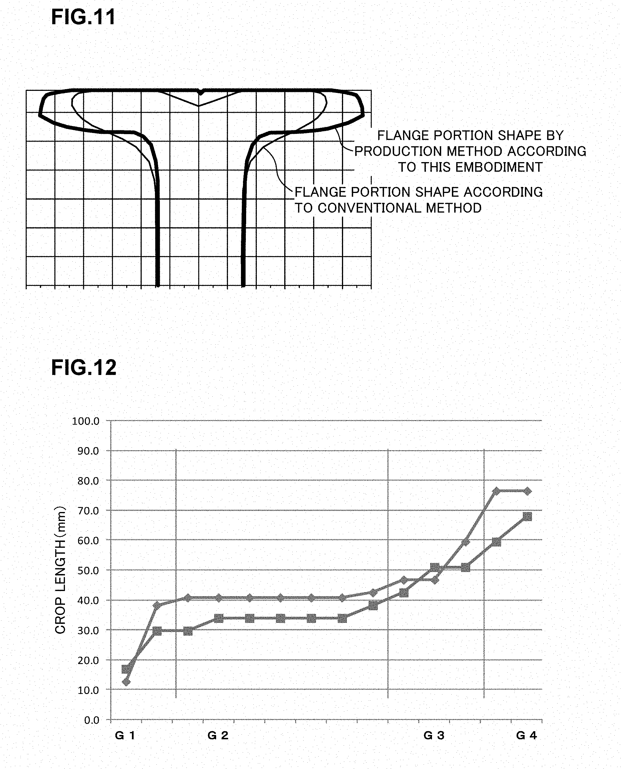
[0033] FIG. 11 is an explanatory view for comparing the shape of a flange portion after edging rolling in the conventional production method and the shape of a flange portion shaped in the first caliber to the fourth caliber according to this embodiment.
[0034] FIG. 12 is a graph illustrating the measurement result of a reference example.
[0035] FIG. 13 is a graph illustrating the measurement result of an example.
BEST MODE FOR CARRYING OUT THE INVENTION
[0036] Hereinafter, an embodiment of the present invention will be explained referring to the drawings. Note that in this description and the drawings, components having substantially the same functional configurations are denoted by the same numerals to omit duplicated explanation.
[0037] FIG. 1 is an explanatory view about a production line T for H-shaped steel including a rolling facility 1 according to this embodiment. As illustrated in FIG. 1, in the production line T, a heating furnace 2, a sizing mill 3, a rough rolling mill 4, an intermediate universal rolling mill 5, and a finishing universal rolling mill 8 are arranged in order from the upstream side. Further, an edger rolling mill 9 is provided close to the intermediate universal rolling mill 5. Note that, in the following, a steel material in the production line T is sometimes collectively described as a "material to be rolled A" for explanation and its shape is sometimes illustrated using broken lines, oblique lines and the like in the drawings.
[0038] As illustrated in FIG. 1, in the production line T, a rectangular cross-section material (a material to be rolled A described later) such as a slab 11 or the like extracted from the heating furnace 2 is subjected to rough rolling in the sizing mill 3 and the rough rolling mill 4. Then, the rectangular cross-section material is subjected to intermediate rolling in the intermediate universal rolling mill 5. During the intermediate rolling, reduction is performed on flange tip portions (flange corresponding portions 12) of the material to be rolled by the edger rolling mill 9 as necessary. In a normal case, edging calibers and so-called flat shaping calibers for decreasing the thickness of a web portion to form the shapes of flange portions are engraved on rolls of the sizing mill 3 and the rough rolling mill 4, and an H-shaped raw blank 13 is shaped by reverse rolling in a plurality of passes through those calibers, and the H-shaped raw blank 13 is subjected to application of reduction in a plurality of passes using a rolling mill train composed of two rolling mills such as the intermediate universal rolling mill 5 and the edger rolling mill 9, whereby an intermediate material 14 is shaped. The intermediate material 14 is subjected to finish rolling into a product shape in the finishing universal rolling mill 8, whereby an H-shaped steel product 16 is produced.
[0039] Here, a slab thickness T of the slab 11 extracted from the heating furnace 2 is in a range of, for example, 240 mm or more and 310 mm or less. This is a slab dimension used in producing a standard H-shaped steel product.
[0040] Next, caliber configurations and caliber shapes engraved on the sizing mill 3 and the rough rolling mill 4 illustrated in FIG. 1 will be explained below referring to the drawings. FIG. 2 to FIG. 6 are schematic explanatory views about calibers engraved on the sizing mill 3 and the rough rolling mill 4 which perform a rough rolling step. All of the first caliber to the fourth caliber explained here may be engraved, for example, on the sizing mill 3, or five calibers such as the first caliber to a fifth caliber may be engraved separately on the sizing mill 3 and the rough rolling mill 4. In other words, the first caliber to the fourth caliber may be engraved across both the sizing mill 3 and the rough rolling mill 4, or may be engraved on one of the rolling mills. In the rough rolling step in production of standard H-shaped steel, shaping in one or a plurality of passes is performed in each of the calibers.
[0041] Besides, a case where there are five calibers to be engraved will be described as an example in this embodiment, and the number of the calibers does not always need to be five, but the number of the calibers may be plural such as five or more. In short, the caliber configuration only needs to be suitable for shaping the H-shaped raw blank 13. Note that in FIG. 2 to FIG. 6, a schematic final pass shape of the material to be rolled A in shaping in each caliber is illustrated by broken lines.
[0042] FIG. 2 is a schematic explanatory view of a first caliber K1. The first caliber K1 is engraved on an upper caliber roll 20 and a lower caliber roll 21 which are a pair of horizontal rolls, and the material to be rolled A is subjected to reduction and shaping in a roll gap between the upper caliber roll 20 and the lower caliber roll 21. Further, a peripheral surface of the upper caliber roll 20 (namely, an upper surface of the first caliber K1) is formed with a projection 25 protruding toward the inside of the caliber. Further, a peripheral surface of the lower caliber roll 21 (namely, a bottom surface of the first caliber K1) is formed with a projection 26 protruding toward the inside of the caliber. These projections 25, 26 have tapered shapes, and dimensions such as a protrusion length of the projection 25 and the projection 26 are configured to be equal to each other. A height (protrusion length) of the projections 25, 26 is h1 and a tip portion angle thereof is .theta. 1a.
[0043] In the first caliber K1, the projections 25, 26 are pressed against upper and lower end portions (slab end surfaces) of the material to be rolled A and thereby form splits 28, 29. Here, a tip portion angle (also called a wedge angle) .theta. 1a of the projections 25, 26 is desirably, for example, 25.degree. or more and 40.degree. or less.
[0044] Here, a caliber width of the first caliber K1 is preferably substantially equal to the thickness of the material to be rolled A (namely, a slab thickness). Specifically, when the width of the caliber at the tip portions of the projections 25, 26 formed in the first caliber K1 is set to be the same as the slab thickness, a right-left centering property of the material to be rolled A is suitably secured. Further, it is preferable that such a configuration of the caliber dimension brings the projections 25, 26 and part of caliber side surfaces (side walls) into contact with the material to be rolled A at upper and lower end portions (slab end surfaces) of the material to be rolled A during shaping in the first caliber K1 as illustrated in FIG. 2 so as to prevent active reduction at the upper surface and the bottom surface of the first caliber K1 from being performed on the slab upper and lower end portions divided into four elements (parts) by the splits 28, 29. This is because the reduction by the upper surface and the bottom surface of the caliber causes elongation of the material to be rolled A in the longitudinal direction to decrease the generation efficiency of the flanges (later-described flange portions 80). In other words, in the first caliber K1, a reduction amount at the projections 25, 26 (reduction amount at wedge tips) at the time when the projections 25, 26 are pressed against the upper and lower end portions (slab end surfaces) of the material to be rolled A to form the splits 28, 29 is made sufficiently larger than a reduction amount at the slab upper and lower end portions (reduction amount at slab end surfaces) and thereby forms the splits 28, 29.
[0045] FIG. 3 is a schematic explanatory view of a second caliber K2. The second caliber K2 is engraved on an upper caliber roll 30 and a lower caliber roll 31 which are a pair of horizontal rolls. A peripheral surface of the upper caliber roll 30 (namely, an upper surface of the second caliber K2) is formed with a projection 35 protruding toward the inside of the caliber. Further, a peripheral surface of the lower caliber roll 31 (namely, a bottom surface of the second caliber K2) is formed with a projection 36 protruding toward the inside of the caliber. These projections 35, 36 have tapered shapes, and dimensions such as a protrusion length of the projection 35 and the projection 36 are configured to be equal to each other. A tip portion angle of the projections 35, 36 is desirably a wedge angle .theta. 1b of 25.degree. or more and 40.degree. or less.
[0046] Note that the wedge angle .theta. 1a of the first caliber K1 is preferably the same angle as the wedge angle .theta. 1b of the second caliber K2 at a subsequent stage in order to ensure the thickness of the tip end portions of the flange corresponding portions, enhance inductive property, and secure stability of tolling.
[0047] A height (protrusion length) h2 of the projections 35, 36 is configured to be larger than the height h1 of the projections 25, 26 of the first caliber K1 so as to be h2>h1. Further, the tip portion angle of the projections 35, 36 is preferably the same as the tip portion angle of the projections 25, 26 in the first caliber K1 in terms of rolling dimension accuracy. In a roll gap between the upper caliber roll 30 and the lower caliber roll 31, the material to be rolled A passed through the first caliber K1 is further shaped.
[0048] Here, the height h2 of the projections 35, 36 formed in the second caliber K2 is larger than the height h1 of the projections 25, 26 formed in the first caliber K1, and an intrusion length into the upper and lower end portions (slab end surfaces) of the material to be rolled A is also similarly larger in the second caliber K2. An intrusion depth into the material to be rolled A of the projections 35, 36 in the second caliber K2 is the same as the height h2 of the projections 35, 36. In other words, an intrusion depth h1' into the material to be rolled A of the projections 25, 26 in the first caliber K1 and the intrusion depth h2 into the material to be rolled A of the projections 35, 36 in the second caliber K2 satisfy a relation of h1'<h2.
[0049] Further, angles .theta. f formed between caliber upper surfaces 30a, 30b and caliber bottom surfaces 31a, 31b facing the upper and lower end portions (slab end surfaces) of the material to be rolled A, and, inclined surfaces of the projections 35, 36, are configured to be about 90.degree. (almost right angle) at all of four locations illustrated in FIG. 3.
[0050] Since the intrusion length of the projections at the time when pressed against the upper and lower end portions (slab end surfaces) of the material to be rolled A is large as illustrated in FIG. 3, shaping is performed to make the splits 28, 29 formed in the first caliber K1 deeper in the second caliber K2 to thereby form the splits 38, 39. Note that based on the dimensions of the splits 38, 39 formed here, a flange half-width at the end of a flange shaping step in the rough rolling step is decided.
[0051] Further, the shaping in the second caliber K2 is performed by multi-pass, and in the multi-pass shaping, shaping is performed to bring the upper and lower end portions (slab end surfaces) of the material to be rolled A into contact with the caliber upper surfaces 30a, 30b and the caliber bottom surfaces 31a, 31b facing them in a final pass. This is because if the upper and lower end portions of the material to be rolled A are made to be out of contact with the inside of the caliber in all passes in the second caliber K2, a shape defect such as flange corresponding portions (parts corresponding to later-described flange portions 80) being shaped to be laterally asymmetrical possibly occurs, bringing about a problem in terms of a material passing property.
[0052] FIG. 4 is a schematic explanatory view of a third caliber K3. The third caliber K3 is engraved on an upper caliber roll 40 and a lower caliber roll 41 which are a pair of horizontal rolls. A peripheral surface of the upper caliber roll 40 (namely, an upper surface of the third caliber K3) is formed with a projection 45 protruding toward the inside of the caliber. Further, a peripheral surface of the lower caliber roll 41 (namely, a bottom surface of the third caliber K3) is formed with a projection 46 protruding toward the inside of the caliber. These projections 45, 46 have tapered shapes, and dimensions such as a protrusion length of the projection 45 and the projection 46 are configured to be equal to each other.
[0053] A tip portion angle .theta. 2 of the projections 45, 46 is configured to be larger than the aforementioned angle .theta. 1b, and an intrusion depth h3 into the material to be rolled A of the projections 45, 46 is smaller than the intrusion depth h2 of the above projections 35, 36 (namely, h3<h2). This angle .theta. 2 is preferably 70.degree. or more and 110.degree. or less.
[0054] Further, angles .theta. f formed between caliber upper surfaces 40a, 40b and caliber bottom surfaces 41a, 41b facing the upper and lower end portions (slab end surfaces) of the material to be rolled A, and, inclined surfaces of the projections 45, 46, are configured to be about 90.degree. (almost right angle) at all of four locations illustrated in FIG. 4.
[0055] As illustrated in FIG. 4, in the third caliber K3, the splits 38, 39 formed in the second caliber K2 at the upper and lower end portions (slab end surfaces) of the material to be rolled A passed through the second caliber K2 are pressed against the projections 45, 46 and thereby become splits 48, 49. Specifically, in a final pass in shaping in the third caliber K3, a deepest portion angle (hereinafter, also called a split angle) of the splits 48, 49 becomes .theta. 2. In other words, shaping is performed so that divided parts (the parts corresponding to the later-described flange portions 80) shaped along with the formation of the splits 38, 39 in the second caliber K2 are bent outward.
[0056] Besides, the shaping in the third caliber K3 illustrated in FIG. 4 is performed by at least one pass or more, and the at least one pass or more are performed with the upper and lower end portions (slab end surfaces) of the material to be rolled A in contact with the inside of the caliber (upper surface and the bottom surface of the third caliber K3). In the state where the upper and lower end portions (slab end surfaces) of the material to be rolled A are in contact with the inside of the caliber, it is preferable to perform light reduction on the end portions.
[0057] FIG. 5 is a schematic explanatory view of a fourth caliber K4. The fourth caliber K4 is engraved on an upper caliber roll 50 and a lower caliber roll 51 which are a pair of horizontal rolls. A peripheral surface of the upper caliber roll 50 (namely, an upper surface of the fourth caliber K4) is formed with a projection 55 protruding toward the inside of the caliber. Further, a peripheral surface of the lower caliber roll 51 (namely, a bottom surface of the fourth caliber K4) is formed with a projection 56 protruding toward the inside of the caliber. These projections 55, 56 have tapered shapes, and dimensions such as a protrusion length of the projection 55 and the projection 56 are configured to be equal to each other.
[0058] A tip portion angle .theta. 3 of the projections 55, 56 is configured to be larger than the aforementioned angle .theta. 2, and an intrusion depth h4 into the material to be rolled A of the projections 55, 56 is smaller than the intrusion depth h3 of the projections 45, 46 (namely, h4<h3).
[0059] Further, angles .theta. f formed between caliber upper surfaces 50a, 50b and caliber bottom surfaces 51a, 51b facing the upper and lower end portions (slab end surfaces) of the material to be rolled A, and, inclined surfaces of the projections 55, 56, are configured to be about 90.degree. (almost right angle) at all of four locations illustrated in FIG. 5 similarly to the above third caliber K3.
[0060] In the fourth caliber K4, the splits 48, 49 formed in the third caliber K3 at the upper and lower end portions (slab end surfaces) of the material to be rolled A passed through the third caliber K3 are pressed against the projections 55, 56 and thereby become splits 58, 59. Specifically, in a final pass in shaping in the fourth caliber K4, a deepest portion angle (hereinafter, also called a split angle) of the splits 58, 59 becomes .theta. 3. In other words, shaping is performed so that divided parts (the parts corresponding to the later-described flange portions 80) shaped along with the formation of the splits 48, 49 in the third caliber K3 are further bent outward. The parts of the upper and lower end portions of the material to be rolled A shaped in this manner are parts corresponding to flanges of a later-described H-shaped steel product and called the flange portions 80 here.
[0061] The shaping in the fourth caliber K4 illustrated in FIG. 5 is performed by at least one pass or more, and at least one pass or more of them are performed with the upper and lower end portions (slab end surfaces) of the material to be rolled A in contact with the inside of the caliber (the upper surface and the bottom surface of the fourth caliber K4). In the state where the upper and lower end portions (slab end surfaces) of the material to be rolled A are in contact with the inside of the caliber, it is preferable to perform light reduction on the end portions.
[0062] FIG. 6 is a schematic explanatory view of a fifth caliber K5. The fifth caliber K5 is composed of an upper caliber roll 85 and a lower caliber roll 86 which are a pair of horizontal rolls. As illustrated in FIG. 6, in the fifth caliber K5, the material to be rolled A shaped until the fourth caliber K4 is rotated 90.degree. or 270.degree., whereby the flange portions 80 located at the upper and lower ends of the material to be rolled A until the fourth caliber K4 are located on a rolling pith line. Then, in the fifth caliber K5, reduction on the web portion 82 being a connecting part connecting the flange portions 80 at two positions and reduction on the flange tip portions of the flange portions 80 are performed to thereby perform dimension adjustment of the flange width. Thus, an H-shaped steel blank in a so-called dog-bone shape (the H-shaped steel blank 13 illustrated in FIG. 1) is shaped. Note that the fifth caliber K5 thins the web portion 82 by reduction, and is therefore called also a web thinning caliber or a flat shaping caliber.
[0063] The H-shaped raw blank 13 thus shaped is subjected to reverse rolling in a plurality of passes using the rolling mill train composed of two rolling mills such as the intermediate universal rolling mill 5 and the edger rolling mill 9 which are already-known rolling mills, whereby an intermediate material 14 is shaped. The intermediate material 14 is subjected to finish rolling into a product shape in the finishing universal rolling mill 8, whereby an H-shaped steel product 16 is produced (refer to FIG. 1).
[0064] The first caliber K1 to the fourth caliber K4 according to this embodiment are used to create splits in the upper and lower end portions (slab end surfaces) of the material to be rolled A and perform processing of bending to right and left the portions separated to right and left by the splits to perform the shaping of forming the flange portions 80 as explained above, thereby enabling shaping of the H-shaped raw blank 13 without performing substantial vertical reduction on the upper and lower end surfaces of the material to be rolled A (slab). In short, it becomes possible to shape the H-shaped raw blank 13 with the flange width made wider as compared with the rough rolling method of reducing at all times the slab end surfaces conventionally performed, resulting in production of a final product (H-shaped steel) having a large flange width.
[0065] Here, in the method for producing H-shaped steel according to this embodiment, the shape of the flange portion 80 of the material to be rolled A shaped by the aforementioned first caliber K1 to fourth caliber K4 is a shape closer to the shape of the product flange as compared with the shape of the flange portion before the shaping in a flat caliber in the conventional production method. This results from employment of a shaping technique of performing the processing of bending the split parts (the flange portions 80) shaped by creating splits without changing the end portion shapes of the material (slab) having the rectangular cross section used as the material. Note that FIG. 11 is an explanatory view for comparing the shape of the flange portion after the edging rolling in the conventional production method and the shape of the flange portion 80 shaped in the above-described first caliber K1 to fourth caliber K4. It is found also from FIG. 11 that the shape of the flange portion shaped by the method for producing H-shaped steel according to this embodiment is a shape closer to the product flange.
[0066] In such a shaping technique, the rolling and shaping is advanced without actively performing reduction on the upper and lower end portions (slab end surfaces) of the material to be rolled A in the shaping in the first caliber K1 to the fourth caliber K4, so that the elongation of the material to be rolled A (in particular, the flange portions 80) in the longitudinal direction becomes extremely small.
[0067] On the other hand, in the conventional H-shaped steel production technique, a configuration is employed which actively performs reduction on the flange portion at an edging rolling stage (corresponding to the rolling and shaping in the first caliber K1 to the fourth caliber K4 in this embodiment), and it has been known that the flange portion is elongated more than the web portion regarding the longitudinal direction of the material to be rolled A to cause a cutoff shape (a so-called crop shape) at the end portion in the longitudinal direction of the material to be rolled, which is a so-called fish tail. Further, it has been known that since the reduction rate of the web portion is larger than the reduction rate of the flange portion, a crop shape called a tongue occurs at a flat caliber rolling stage (the rolling and shaping in the fifth caliber K5 in this embodiment). Hereinafter, the crop shapes will be described referring to FIG. 7.
[0068] FIG. 7 is a schematic explanatory view regarding the conventional H-shaped steel production technique, (a) is a schematic side view of the conventional edging rolling as seen from the side, and (b) is a schematic plan view of the conventional flat caliber rolling as seen from above. Note that the left side in FIG. 7 indicates a rolling upstream side.
[0069] As illustrated in FIG. 7(a), in the conventional H-shaped steel production technique, since reduction on the flange portion is actively performed at the edging rolling stage, the elongation of the flange portion exceeds the elongation of the web portion in the longitudinal direction of the material to be rolled A and a crop-shaped portion 90 being a so-called fish tail comes to be formed (refer to a broken line portion in FIG. 7(a)).
[0070] Thereafter, as illustrated in FIG. 7(b), in the conventional H-shaped steel production technique, since the reduction rate of the web portion is relatively larger than that of the flange portion at the flat caliber rolling stage, the elongation of the web portion exceeds the elongation of the flange portion in the longitudinal direction of the material to be rolled A and a crop-shaped portion 92 being a so-called tongue comes to be formed (refer to a broken line portion in FIG. 7(b)).
[0071] The crop-shaped portion 90, 92 called a fish tail or a tongue is formed and grown at both a rolling bite end and a rolling ejection end, and it is known that the growth at the rolling ejection end is significant.
[0072] Note that the length in the longitudinal direction of the crop-shaped portion 90 thus formed is L1, and the length in the longitudinal direction of the crop-shaped portion 92 is L2.
[0073] The crop-shaped portion 90, 92 thus formed possibly causes a bite defect into the rolling mill at a subsequent step (intermediate rolling step) and has a problem of difficulty in continuing the intermediate rolling. Specifically, the crop-shaped portion 90, 92 illustrated in FIG. 7(b) causes the following problem.
[0074] More specifically, in the case where the crop-shaped portion 90 called a fish tail has been formed, the flange portion of the material to be rolled A is rolled between a horizontal roll side surface and a vertical roll during the universal rolling in the intermediate rolling being the subsequent step and the vertical roll is normally an undriven roll, thus easily leading to folding of the material to be rolled A on the exit side of the universal rolling mill and to rolling that the material to be rolled A is drawn into a chock. Further, the crop-shaped portion 90 in a shape such as the flange portion preceding has a possibility that when an upper-lower deviation occurs at the time of bite in the rolling mill, the rolling mill bites the flange portion as it is and the web portion is replaced to lead to a serious rolling trouble and degradation in dimension, such as tearing a base portion being the web-flange connecting part.
[0075] Besides, the crop-shaped portion 92 in a shape such a the web preceding has a possibility that when a right-left deviation occurs at the time of bite in the rolling mill, the rolling mill rolls the flange portion at a position as it is to lead to a serious rolling trouble and degradation in dimension, such as tearing a base portion being the web-flange connecting part.
[0076] In consideration of existence of the various problems leading to degradation in dimension, the conventional H-shaped steel production technique copes with the problems by providing an intermediate crop cutting step of cutting the above-described crop-shaped portion 90 or crop-shaped portion 92 as a cutoff portion, for example, between the rough rolling step and the intermediate rolling step.
[0077] In consideration of the above circumstance described referring to FIG. 7, the present inventors have examined the technique of suppressing the growth of the crop-shaped portion 90 and crop-shaped portion 92 formed at the rough rolling step (edging rolling and flat caliber rolling) and found the knowledge described below.
[0078] Though the use of the first caliber K1 to the fifth caliber K5 for the rolling and shaping has been described in FIG. 2 to FIG. 6 in the method for producing H-shaped steel according to this embodiment, the caliber roll engraved with a caliber can be freely changed in roll gap in the rolling using these calibers. Further, the change in the roll gap can be performed during rolling and shaping of the material to be rolled A, and the reduction amount can also be changed. Note that the change in the roll gap is performed, for example, by employing a rolling mill (a sizing mill 3, a rough rolling mill 4) having a configuration provided with a reduction mechanism (a hydraulic mechanism, not illustrated in FIG. 2 to FIG. 6) for moving the caliber roll to change the roll gap.
[0079] Based on the configuration of the rolling mill, the present inventors have invented performing rolling and shaping using one or any number of calibers by a method called AGC (Automatic Gage Control) rough rolling at the time when performing the rolling and shaping using the first caliber K1 to the fifth caliber K5. The AGC rough rolling is a technique of expanding the roll gap only when rolling and shaping a section of a predetermined length at a rear end portion in the longitudinal direction of the material to be rolled A to make the reduction amount in the caliber lower than the normal reduction amount or set the reduction amount to 0, in all of the passes in each of which the material to be rolled A is reciprocated, for example, in the case of performing reverse rolling in a plurality of passes on the material to be rolled A in one caliber. Note that the caliber which performs the AGC rough rolling may be any one of the first caliber K1 to the fifth caliber K5 or may be a plurality of, namely two or more calibers of them.
[0080] As described above, in the conventional production technique, the crop-shaped portion 90, 92 called a fish tail or a tongue is formed and grown at both a rolling bite end and a rolling ejection end, and the growth, in particular, at the rolling ejection end is significant, but the growth of the crop-shaped portion 90, 92 can be suppressed by decreasing the reduction amount for the predetermined section or set the reduction amount to 0 by applying the AGC rough rolling.
[0081] FIG. 8 is a schematic explanatory view in the case of applying the AGC rough rolling to the rolling and shaping in the first caliber K1 in the method for producing H-shaped steel according to this embodiment, and is a schematic side view as seen from the side. Note that FIG. 8 illustrates the material to be rolled A before rolling and shaping in a certain pass (on a left side in the drawing), the material to be rolled A directly before the end of the rolling and shaping in the pass (at a middle in the drawing), and the material to be rolled A after the end of the rolling and shaping in the pass (on a right side in the drawing) for explanation.
[0082] As illustrated in FIG. 8, in the certain pass in the rolling and shaping in the first caliber K1 according to this embodiment, the rolling and shaping is performed in a required roll gap (the interval between the upper caliber roll 20 and the lower caliber roll 21) for performing the rolling and shaping illustrated in FIG. 2 from start of the rolling and shaping until directly before the end of the rolling and shaping. On the other hand, the rolling and shaping is performed with the roll gap expanded (refer to a broken line portion in FIG. 8) in the rolling and shaping for a predetermined section L from directly before the end of the rolling and shaping until the end of the rolling and shaping in the pass. Specifically, the roll gap may be expanded stepwise to gradually decrease the reduction amount from directly before the end of the rolling and shaping, or the roll gap may be greatly expanded to set the reduction amount to 0.
[0083] In the rolling and shaping performed in the above manner, the rolling and shaping is performed on the material to be rolled A with the reduction amount smaller for the predetermined section L than that for other sections (or with no reduction amount), so that not so much reduction is performed in the longitudinal direction of the material to be rolled A. Accordingly, it rarely occurs that the elongation of the flange portion exceeds the elongation of the web portion at the edging rolling stage and a shape defective portion being a so-called fish tail is formed described above referring to FIG. 7(a). In other words, the reduction amount for the predetermined section L decreases or becomes 0 at the rolling ejection end, thus suppressing the growth of the crop-shaped portion 90 as described above. Therefore, the above-described omission or simplification of the intermediate crop cutting step becomes possible to realize the improvement in yield and efficient rolling.
[0084] Note that in the case of employing the reverse rolling at the edging rolling stage, in a pass next to the pass described in FIG. 8, rolling and shaping is performed in a direction opposite to the direction indicated in FIG. 8, so that the predetermined section L is at the bite end. At this time, the roll gap is set to be a roll gap enabling the predetermined rolling and shaping, and therefore the rolling and shaping is performed for the predetermined section L as the bite end in this pass. In short, sufficient rolling and shaping is performed also for the predetermined section L.
[0085] Here, though the first caliber K1 is exemplified for explanation in FIG. 8, the same operation and effect also applies to each caliber used at the edging rolling stage, and the AGC rough rolling is also applicable to one or a plurality of calibers used at the edging rolling stage.
[0086] At the rough rolling step according to this embodiment described above referring to FIG. 2 to FIG. 6, the crop growth is significant, in particular, in the first caliber K1 for forming first splits on the slab end surfaces and in the third caliber K3 and the fourth caliber K4 for performing shaping of bending divided parts formed by the splits, of the edging rolling stage. This is because edging is performed in a strong constraint state by the caliber side wall at the step of forming the first splits on the slab end surfaces, and is because a predetermined amount of reduction is loaded in the slab width direction during bending deformation and the slab end surfaces are finally edged while in contact with the caliber peripheral surface at the step of bending the divided parts. This is clear also from the fact that the crop length grows mainly at G1 and G3 in G1 to G3 corresponding to the edging rolling in the first caliber K1 to the third caliber K3 in a later-described example (refer to FIG. 10).
[0087] More specifically, it is preferable to apply, in particular, the AGC rough rolling to the first caliber K1, and/or, an edging rolling and shaping caliber in the third caliber K3 and subsequent calibers (the third caliber K3 and the fourth caliber K4 in this embodiment) where the shape defective portion being a so-called fish tail is possibly formed.
[0088] Note that the AGC rough rolling does not always have to be applied to the second caliber K2 for performing shaping to further deepen the splits formed in the first caliber K1 because the growth of the shape defective portion (crop portion) is small.
[0089] However, also in the second caliber K2, in a pass in which reduction is performed with the end surfaces of the material to be rolled and the caliber peripheral surface in contact with each other, the growth of the crop portion is larger than in other passes. Accordingly, it is preferable to perform rolling and shaping with the rolling roll gap for the predetermined section at the rear end portion in the rolling longitudinal direction of the material to be rolled expanded as compared with the rolling roll gap for other than the predetermined section in a pass in which reduction is performed with the end surfaces of the material to be rolled and the caliber peripheral surface in contact with each other also in the rolling and shaping in the second caliber K2.
[0090] Further, in the predetermined section in which the rolling and shaping is performed with the rolling roll gap expanded, the end surfaces of the material to be rolled and the caliber peripheral surface do not have to be in contact with each other. However, when the pass in which the end surfaces of the material to be rolled and the caliber peripheral surface are in contact with each other is one pass, an unreduced portion possibly remains at the rear end portion in the longitudinal direction of the material to be rolled, and therefore the contact pass needs to be increased by one to arrange the shape in some cases. In such a case, the AGC rough rolling may be performed in all passes in the second caliber K2.
[0091] Further, FIG. 9 is a schematic explanatory view in the case of applying the AGC rough rolling to the rolling and shaping in the fifth caliber K5 (flat shaping caliber) in the method for producing H-shaped steel according to this embodiment, and is a schematic plan view as seen from above. Note that FIG. 9 illustrates the material to be rolled A before rolling and shaping in a certain pass (on a left side in the drawing), and the material to be rolled A after end of the rolling and shaping in the pass (on a right side in the drawing) for explanation.
[0092] As illustrated in FIG. 9, also in the flat caliber rolling in the fifth caliber K5, the rolling and shaping is performed in a required roll gap for performing the rolling and shaping illustrated in FIG. 6 from start of the rolling and shaping until directly before the end of the rolling and shaping as at the above described edging rolling stage. On the other hand, the rolling and shaping is performed with the roll gap expanded in the rolling and shaping for the predetermined section L from directly before the end of the rolling and shaping until the end of the rolling and shaping in the pass. Specifically, the roll gap may be expanded stepwise to gradually decrease the reduction amount from directly before the end of the rolling and shaping, or the roll gap may be greatly expanded to set the reduction amount to 0.
[0093] In the rolling and shaping performed in the above manner, the rolling and shaping is performed on the material to be rolled A with the reduction amount smaller for the predetermined section L than that for other sections (or with no reduction amount), so that not so much reduction is performed on both the flange portion and the web portion in the longitudinal direction of the material to be rolled A. Accordingly, even in the case where the reduction rate on the web portion is relatively large as compared with that on the flange portion at the flat caliber rolling stage, the reduction rate itself is extremely low, so that a shape defective portion being a so-called tongue (refer to FIG. 7(b)) is not significantly formed as illustrated in FIG. 9 even if the elongation of the web portion exceeds the elongation of the flange portion in the longitudinal direction of the material to be rolled A. In other words, the reduction amount in the predetermined section L decreases or becomes 0 at the rolling ejection end, thus suppressing the growth of the crop-shaped portion 92 as described above. Therefore, the above-described omission or simplification of the intermediate crop cutting step becomes possible to realize the improvement in yield and efficient rolling.
[0094] Note that the reverse rolling is performed also at the flat caliber rolling stage, so that in a pass next to the pass described in FIG. 9, rolling and shaping is performed in a direction opposite to the direction indicated in FIG. 9. In other words the predetermined section L becomes the bite end in the next pass. At this time, the roll gap is set to be a roll gap enabling the predetermined rolling and shaping, and therefore the rolling and shaping is performed for the predetermined section L as the bite end in this pass. In short, sufficient rolling and shaping is performed also for the predetermined section L. However, as the reduction amount relating to the predetermined section L in a pass next to the pass described in FIG. 9, the reduction amount in the next pass needs to be simultaneously applied in addition to the reduction amount in the pass at the preceding stage, and therefore it is important to sufficiently examine the reduction amount for the predetermined section L in the design of the pass schedule.
[0095] The case of applying the AGC rough rolling at the edging rolling stage (FIG. 8) and the case of applying the AGC rough rolling in the flat caliber rolling stage (FIG. 9) have been described referring to FIG. 8 and FIG. 9 respectively. In the case of applying the AGC rough rolling in the method for producing H-shaped steel according to this embodiment, the AGC rough rolling may be applied only to the edging rolling stage (namely, the rolling and shaping corresponding to the first caliber K1 to the fourth caliber K4), only to the flat caliber rolling stage (namely, the rolling and shaping corresponding to the fifth caliber K5), and to both the edging rolling stage and the flat caliber rolling stage. In any of the cases, it is possible to omit or simplify the intermediate crop cutting step to realize the improvement in yield and efficient rolling.
[0096] Besides, in the case of employing the reverse rolling in each of the rolling and shaping stages, the AGC rough rolling may be applied to a predetermined arbitrary pass or may be applied to all passes. From the viewpoint that it is desirable to suppress the growth of the crop portion without forming the shape defective portion, it is desirable to apply the AGC rough rolling to all passes.
[0097] Note that regarding the case of applying the AGC rough rolling described referring to FIG. 8 and FIG. 9, the predetermined section L for which the rolling and shaping is required to be performed with the roll gap expanded can be arbitrarily set. For example, the sections L1, L2 in the longitudinal direction of the material to be rolled A where the shape defective portions 90, 92 formed in the conventional H-shaped steel production technique described referring to FIG. 7(a), (b) are preferably set as the above-described predetermined section L.
[0098] At the time when deciding the predetermined section L, it is necessary to clarify the boundary between an unsteady part and a steady part in rolling of the material to be rolled A and to make at least the unsteady part be included in the predetermined section L. If the steady part is included in the predetermined section L, the roll gap is expanded in a part of the range of the steady part to possibly causes residual reduction in the steady part. However, since there is little influence caused by shift of reduction in the steady part to a pass at a subsequent stage, the predetermined section L preferably takes a range including the whole range of the unsteady part and expandable to a part of the steady part. At the time when concretely deciding the predetermined section L, the predetermined section L will be decided based on all elements such as the material cross section, dimension of the material to be rolled, caliber shape, pass schedule and so on, and therefore a laboratory experiment or an actual machine test will be performed to measure the unsteady part length for each pass so as to decide a preferable length.
[0099] According to the method for producing H-shaped steel according to this embodiment described above, creating splits in the upper and lower end portions (slab end surfaces) of the material to be rolled A and performing processing of bending to right and left the portions separated to right and left by the splits to perform the shaping of forming the flange portions 80, enables shaping of the H-shaped raw blank 13 substantially without performing vertical reduction on the upper and lower end surfaces of the material to be rolled A (slab). In short, it becomes possible to shape the H-shaped raw blank 13 with the flange width made wider as compared with the rough rolling method of reducing at all times the slab end surfaces conventionally performed, resulting in production of a final product (H-shaped steel) having a large flange width.
[0100] Further, in addition to the above operation and effect, according to the method for producing H-shaped steel according to this embodiment, expanding the roll gap at the rolling and shaping for the predetermined section L (a rear end at the rolling and shaping) of the material to be rolled A and performing the AGC rough rolling, at the edging rolling stage (namely, the rolling and shaping corresponding to the first caliber K1 to the fourth caliber K4), and/or, the flat caliber rolling stage (namely, the rolling and shaping corresponding to the fifth caliber K5), makes it possible to suppress the growth of the shape defective portion at the rear end portion in the longitudinal direction of the material to be rolled formed in the conventional H-shaped steel production technique. This enables omission or simplification of the intermediate crop cutting step to realize the improvement in yield and efficient rolling. In other words, most ideally, all of the rough rolling step, the intermediate rolling step, and the finish rolling step can be performed without the intermediate crop cutting step intervening therebetween. Only performing the cop cutting after all steps (the rough rolling step, the intermediate rolling step, and the finish rolling step) enables completion of removal of the crop portion caused in the longitudinal direction of the material to be rolled. Note that the intermediate crop cutting step may be performed as necessary only on the web portion of the material to be rolled after the rough rolling step and at a preceding stage or at a middle stage of the intermediate rolling step (between rolling passes at the intermediate rolling step).
[0101] In particular, in production of a large-size H-shaped steel product having a web height of 1000 mm or more or a flange width of 400 mm or more, the weight per unit length of the material to be rolled A is large and the elongation length of the product at rolling is small, and therefore the proportion of the crop portion in the whole length is large, and growth of the crop portion is likely to lead to the decrease in yield. Accordingly, the technique of suppressing the growth of the crop portion according to this embodiment is useful particularly in producing the large-size H-shaped steel product.
[0102] One example of the embodiment of the present invention has been explained above, but the present invention is not limited to the illustrated embodiment. It should be understood that various changes and modifications are readily apparent to those skilled in the art within the scope of the spirit as set forth in claims, and those should also be covered by the technical scope of the present invention.
[0103] The technique of performing the shaping on the material to be rolled A using four calibers such as the first caliber K1 to the fourth caliber K4 and then performing the flat shaping and rolling thereon using the fifth caliber K5 has been explained in the above embodiment. However, the number of calibers for performing the rough rolling step is not limited to this, but much more calibers may be used to perform the rolling and shaping step represented by the first caliber K1 to the fourth caliber K4. In other words, the caliber configuration illustrated in the above embodiment is one example, and the number of calibers engraved on the sizing mill 3 and the rough rolling mill 4 can be arbitrarily changed and appropriately changed to an extent at which the rough rolling step can be suitably performed.
[0104] Further, explanation has been made by exemplifying a slab as a material when producing H-shaped steel, but the present invention is naturally applicable also to other materials in a similar shape. In other words, the present invention is also applicable to a case of shaping, for example, a beam blank material to produce H-shaped steel.
EXAMPLES
[0105] The effect of the present invention will be verified using examples.
[0106] In the following, the result of an experiment carried out to compare the production method (hereinafter, also called a wedge method) according to the conventional H-shaped steel production technique exemplified in Patent Document 1 or the like and the production method (hereinafter, also called a split method) according to the technique of the present invention is illustrated first as Experimental Example 1. In addition, the result of an experiment of comparing the presence or absence of application of a so-called "AGC rough rolling" described in the above embodiment carried out in the split method is illustrated as Experimental Example 2.
Experimental Example 1
[0107] As Reference Example 1, the edging rolling was performed using the H-shaped steel production technique by the wedge method being the conventional method and the length of the crop portion (crop length) at that time was measured. Meanwhile, as Reference Example 2, the edging rolling by the split method was performed using the first caliber K1 to the third caliber K3 illustrated in FIG. 2 to FIG. 4 and the length of the crop portion at that time was measured. Note that as the conditions of this verification, the material slab cross section was set to 1800 mm.times.300 mm and the wedge angle in the edging rolling in the example was set to 30.degree. in the first caliber K1 and the second caliber K2 and set to 90.degree. in the third caliber K3. Further, the edging amount was set to the reduction amount at the projection tip end position (wedge tip position) in each caliber.
[0108] FIG. 10 is a graph illustrating the verification results of Reference Example 1 (the wedge method in the drawing) and Reference Example 2 (the split method in the drawing), and is a graph illustrating the relation between the edging amount (reduction amount by the edging rolling) and the crop length in each of the cases. Note that indication of G1 to G3 in FIG. 10 corresponds to the edging rolling in the first caliber K1 to the third caliber K3 according to the above embodiment. Besides, the plot in FIG. 10 is made by calculating the average value of the crop lengths at both ends in the longitudinal direction of the material to be rolled.
[0109] As illustrated in FIG. 10, in Reference Example 1, the crop length grew in substantially proportional to the edging amount, and the crop length grew up to about 250 mm, for example, when the edging amount was 600 mm.
[0110] On the other hand, in Reference Example 2, little growth was observed in the crop length, but the growth of the crop portion was not observed, in particular, in the second caliber K2 (G2 in the drawing), showing that the growth of the crop length was suppressed as compared with a comparison example. For example, the crop length stays at about 80 mm when the edging amount is 900 mm.
Experimental Example 2
[0111] As a comparative example, the edging rolling was performed by the split method using the first caliber K1 to the fourth caliber K4 illustrated in FIG. 2 to FIG. 5 without applying the AGC rough rolling, and the length of the crop portions (crop lengths) at both ends of the material to be rolled at that time were measured. FIG. 12 is a graph illustrating the measurement result of the comparative example, and two plots in the graph indicate the crop lengths at both ends in the longitudinal direction of the material to be rolled.
[0112] Further, as an example, the AGC rough rolling was performed in all passes of the rolling and shaping in the first caliber K1, the third caliber K3, and the fourth caliber K4 (corresponding to G1, G3, G4 in the drawing respectively) in the split method using the first caliber K1 to the fourth caliber K4 illustrated in FIG. 2 to FIG. 5, and the lengths of the crop portions (crop lengths) at both ends of the material to be rolled at that time were measured. FIG. 13 is a graph illustrating the measurement result of the example, and two plots in the graph indicate the crop lengths at both ends in the longitudinal direction of the material to be rolled.
[0113] In the case where the AGC rough rolling was performed in the example, the roll gap was expanded from about 400 mm at the terminal end portion of the material to be rolled and the roll was opened at the final end portion in each rolling pass.
[0114] Note that the material slab used in the comparison example and the example is a slab having a cross section of 2300 mm.times.300 mm and a length of 4000 mm. Besides, the rolling pass schedule in each caliber is as listed in following Table 1.
TABLE-US-00001 TABLE 1 PASS CALIBER ROLL GAP (mm) 1 G1 2200 2 G1 2120 3 G2 2000 4 G2 1900 5 G2 1800 6 G2 1700 7 G2 1600 8 G2 1500 9 G2 1460 10 G3 1460 11 G3 1460 12 G3 1416 13 G4 1416 14 G4 1416
However, the "roll gap" in Table 1 indicates the interval (distance) between wedge (projection) tip end portions of the upper and lower rolls of the caliber, and is synonymous with the "edging amount" in above Experimental Example 1.
[0115] As is found from the comparison in FIG. 12 and FIG. 13, the crop growth amount in each caliber is suppressed in the case of applying the AGC rough rolling (FIG. 13) as compared with the case of not applying the AGC rough rolling (FIG. 12). In particular, the crop growth amount at G1, G3, G4 (corresponding to the first caliber K1, the third caliber K3, and the fourth caliber K4) are greatly suppressed. The final crop length was little less than about 40 mm in the case of applying the AGC rough rolling and was little less than about 90 mm in the case of not applying the AGC rough rolling, so that the crop length became 1/2 or less by applying the AGC rough rolling.
[0116] The result of above Experimental Example 2 shows that the growth of the crop length is greatly suppressed at the edging rolling stage in the H-shaped steel production technique applying the AGC rough rolling according to the present invention. This makes it possible to perform the rolling and shaping without performing the intermediate crop cutting step which has been constantly performed in the conventional H-shaped steel production technique. In other words, the improvement in yield and efficient rolling are realized.
INDUSTRIAL APPLICABILITY
[0117] The present invention is applicable to a producing technique of producing H-shaped steel using a slab or the like having, for example, a rectangular cross section as a material.
EXPLANATION OF CODES
[0118] 1 rolling facility [0119] 2 heating furnace [0120] 3 sizing mill [0121] 4 rough rolling mill [0122] 5 intermediate universal rolling mill [0123] 8 finishing universal rolling mill [0124] 9 edger rolling mill [0125] 11 slab [0126] 13 H-shaped raw blank [0127] 14 intermediate material [0128] 16 H-shaped steel product [0129] 20 upper caliber roll (first caliber) [0130] 21 lower caliber roll (first caliber) [0131] 25, 26 projection (first caliber) [0132] 28, 29 split (first caliber) [0133] 30 upper caliber roll (second caliber) [0134] 31 lower caliber roll (second caliber) [0135] 35, 36 projection (second caliber) [0136] 38, 39 split (second caliber) [0137] 40 upper caliber roll (third caliber) [0138] 41 lower caliber roll (third caliber) [0139] 45, 46 projection (third caliber) [0140] 48, 49 split (third caliber) [0141] 50 upper caliber roll (fourth caliber) [0142] 51 lower caliber roll (fourth caliber) [0143] 55, 56 projection (fourth caliber) [0144] 58, 59 split (fourth caliber) [0145] 80 flange portion [0146] 82 web portion [0147] 85 upper caliber roll (fifth caliber) [0148] 86 lower caliber roll (fifth caliber) [0149] 90, 92 crop-shaped portion [0150] K1 first caliber [0151] K2 second caliber [0152] K3 third caliber [0153] K4 fourth caliber [0154] K5 fifth caliber (flat shaping caliber) [0155] T production line [0156] A material to be rolled
* * * * *
D00000
D00001
D00002
D00003
D00004
D00005
D00006
D00007
D00008
XML
uspto.report is an independent third-party trademark research tool that is not affiliated, endorsed, or sponsored by the United States Patent and Trademark Office (USPTO) or any other governmental organization. The information provided by uspto.report is based on publicly available data at the time of writing and is intended for informational purposes only.
While we strive to provide accurate and up-to-date information, we do not guarantee the accuracy, completeness, reliability, or suitability of the information displayed on this site. The use of this site is at your own risk. Any reliance you place on such information is therefore strictly at your own risk.
All official trademark data, including owner information, should be verified by visiting the official USPTO website at www.uspto.gov. This site is not intended to replace professional legal advice and should not be used as a substitute for consulting with a legal professional who is knowledgeable about trademark law.