Intelligent Control Method For Air Condition Device
CHAN; Ping-Chieh ; et al.
U.S. patent application number 16/101838 was filed with the patent office on 2019-01-24 for intelligent control method for air condition device. The applicant listed for this patent is DELTA ELECTRONICS, INC.. Invention is credited to Ping-Chieh CHAN, Hua-Yi HSIEH, Yuan-Ping HSIEH, Cheng-Yi HUANG.
| Application Number | 20190022567 16/101838 |
| Document ID | / |
| Family ID | 55301432 |
| Filed Date | 2019-01-24 |


View All Diagrams
| United States Patent Application | 20190022567 |
| Kind Code | A1 |
| CHAN; Ping-Chieh ; et al. | January 24, 2019 |
INTELLIGENT CONTROL METHOD FOR AIR CONDITION DEVICE
Abstract
An intelligent control method applied in an intelligent control system that is having an air condition device, an intelligent control device, and a temperature sensor unit is disclosed and including following steps of: sensing and recording a set of first temperature values of a first time segment with the temperature sensor unit in the first time segment before the air condition device is started; calculating a temperature reference value by the intelligent control device according to the set of first temperature values after the air condition device is started; fine adjusting the temperature reference value by the intelligent control device according to a humidity value currently in the area; and, querying a mode association table by the intelligent control device according to fine adjusted temperature reference value to determine an operation mode of the air condition device.
| Inventors: | CHAN; Ping-Chieh; (Taoyuan City, TW) ; HSIEH; Hua-Yi; (Taoyuan City, TW) ; HUANG; Cheng-Yi; (Taoyuan City, TW) ; HSIEH; Yuan-Ping; (Taoyuan City, TW) | ||||||||||
| Applicant: |
|
||||||||||
|---|---|---|---|---|---|---|---|---|---|---|---|
| Family ID: | 55301432 | ||||||||||
| Appl. No.: | 16/101838 | ||||||||||
| Filed: | August 13, 2018 |
Related U.S. Patent Documents
| Application Number | Filing Date | Patent Number | ||
|---|---|---|---|---|
| 14826414 | Aug 14, 2015 | 10086322 | ||
| 16101838 | ||||
| 62038076 | Aug 15, 2014 | |||
| Current U.S. Class: | 1/1 |
| Current CPC Class: | G05D 23/1928 20130101; G05B 19/0428 20130101; F24F 2120/10 20180101; F24F 11/62 20180101; G05D 23/1919 20130101; Y02D 70/142 20180101; F24F 11/39 20180101; Y02D 70/162 20180101; F24F 3/1603 20130101; G05B 19/048 20130101; Y02D 70/166 20180101; Y02D 70/448 20180101; Y02D 30/70 20200801; H04L 12/2827 20130101; F24F 11/30 20180101; F24F 2110/40 20180101; G05B 19/042 20130101; G05B 2219/2614 20130101; Y02P 90/84 20151101; Y02D 70/144 20180101; H04B 7/24 20130101; B01D 46/0086 20130101; F24F 11/79 20180101; Y02D 70/26 20180101 |
| International Class: | B01D 46/00 20060101 B01D046/00; H04L 12/28 20060101 H04L012/28; H04B 7/24 20060101 H04B007/24; F24F 11/62 20180101 F24F011/62; F24F 11/39 20180101 F24F011/39; F24F 11/30 20180101 F24F011/30; F24F 11/79 20180101 F24F011/79; F24F 3/16 20060101 F24F003/16; G05B 19/042 20060101 G05B019/042; G05B 19/048 20060101 G05B019/048; G05D 23/19 20060101 G05D023/19 |
Claims
1. An intelligent control method of air condition device applied in an intelligent control system disposed in an area and having an air condition device, an intelligent control device having a temperature sensor unit for sensing surrounding temperature and humidity of the intelligent control device, the intelligent control method comprising: a) sensing and recording a set of first temperature values of a first-time segment with the temperature sensor unit in the first-time segment before the air condition device is started; b) calculating a temperature reference value by the intelligent control device according to the set of first temperature values after the air condition device is started; c) fine adjusting the temperature reference value by the intelligent control device according to a humidity value currently in the area; and d) querying a mode association table by the intelligent control device according to fine adjusted temperature reference value to determine an operation mode of the air condition device.
2. The intelligent control method of claim 1, wherein the mode association table records a relation between the temperature reference value and a plurality of the operation modes of the air condition device, and in the step d), the air condition device is controlled by the intelligent control device to adopt a cool mode out of the plurality of operation modes when the temperature reference value is higher than 25.degree. C., the air condition device is controlled by the intelligent control device to adopt a heating mode out of the plurality of operation modes when the temperature reference value is lower than 16.degree. C., and the air condition device is controlled by the intelligent control device to adopt a fan mode out of the plurality of operation modes when the temperature reference value is between 16.degree. C. and 25.degree. C.
3. The intelligent control method of claim 1, further comprising: e) sensing and recording a set of second temperature values in a second time segment via the temperature sensor unit after the step d); f) calculating a temperature compared value by the intelligent control device according to the set of second temperature values; g) switching the operation mode of the air condition device to a cool mode by the intelligent control device when the temperature compared value being larger than a predetermined temperature; h) switching the operation mode of the air condition device to a fan mode by the intelligent control device when the temperature compared value is smaller than the predetermined temperature; and i) repeating the step e to step h before the air condition device is turned off.
4. The intelligent control method of claim 3, wherein the intelligent control system further comprises a mobile device wirelessly connected to the intelligent control device, the mobile device is configured to sense user information and receive feedback information, and the intelligent control device is configured to adjust the time lengths of the first-time segment and the second time segment according to the user information and the feedback information.
5. The intelligent control method of claim 4, wherein the mobile device is a smart phone or a smart watch capable of sensing the user information, and the user information at least contains temperatures and heartbeats of a user.
6. The intelligent control method of claim 4, wherein the mobile device is installed with an app for providing a motion sensing feedback interface for receiving the user to input the feedback information and for transmitting the user information and the feedback information to the intelligent control device.
7. An intelligent control method of air condition device used in an intelligent control system, the intelligent control system being disposed in an area, and having an air condition device, an intelligent control device wirelessly connecting to the air condition, and a plurality of sensor beacons wirelessly connected to the intelligent control device, the intelligent control method comprising: a) sensing and recording a set of first temperature values with the plurality of sensor beacons, wherein the set of first temperature values comprise a plurality of temperature data in the area within a first-time segment before the air condition device is turned on; b) retrieving a temperature reference value by calculating an average value of the set of first temperature values by the intelligent control device after the air condition device is started; c) calculating a humidity associated value according to a humidity value currently in the area by the intelligent control device; d) adjusting the temperature reference value according to the humidity associated value by the intelligent control device; e) controlling the started air condition device to operate with a cool mode by the intelligent control device if the adjusted temperature reference value being larger than 25.degree. C.; f) controlling the started air condition device to operate with a heating mode by the intelligent control device if the adjusted temperature reference value being smaller than 25.degree. C.; and g) controlling the started air condition device to operate with a fan mode by the intelligent control device if the adjusted temperature reference value being between 16.degree. C. and 25.degree. C.
8. The intelligent control method of claim 7, further comprising: h) sensing and recording a set of second temperature values when the air condition device is started and operated in the cool mode, the heating mode or the fan mode, wherein the set of second temperature values are recorded as a plurality of temperature data in the area after the air condition device is started and within a second time segment; i) retrieving a temperature compared value by calculating an average value of the set of second temperature values by the intelligent control device; j) controlling the air condition device to operate in the cool mode by the intelligent control device when the temperature compared value being larger than a predetermined value; k) controlling the air condition device to operate in the fan mode by the intelligent control device when the temperature compared value being smaller than the predetermined value; and l) repeating the step h to k before the air condition device is turned off.
9. The intelligent control method of claim 8, wherein the intelligent control device is configured to capture a biological feature of a user and perform identity recognition with an image capture device to determine whether the user enters the area, and the intelligent control device is configured to start the air condition device when determining that the user enters the area.
10. The intelligent control method of claim 8, wherein the intelligent control system further comprises a mobile device wirelessly connected to the intelligent control device, the mobile device is configured to sense user information of a user and is installed with an app for providing motion sensor feedback interface for receiving the user to input feedback information, the mobile device is configured to transmit the user information and the feedback information to the intelligent control device via the app, wherein the user information at least comprises body temperature and heartbeats of the user and the mobile device is a smart phone or a smart watch capable of sensing the user information.
11. An intelligent control method of air condition device applied in an intelligent control system disposed in an area and having an air condition device, an intelligent control device, and a plurality of sensor beacons wirelessly connected to the intelligent control device, the intelligent control method comprising: a) sensing and recording a set of first temperature values of a first-time segment with the plurality of sensor beacons in the first-time segment before the air condition device is started; b) calculating a temperature reference value by the intelligent control device according to the set of first temperature values after the air condition device is started; c) fine adjusting the temperature reference value by the intelligent control device according to a humidity value currently in the area; and d) querying a mode association table by the intelligent control device according to fine adjusted temperature reference value to determine an operation mode of the air condition device.
Description
CROSS-REFERENCE TO RELATED APPLICATION
[0001] This application is a continuation application of U.S. patent application Ser. No. 14/826,414, filed on Aug. 14, 2015, and entitled "INTELLIGENT CONTROL METHOD FOR AIR CONDITION DEVICE," which claims priority to U.S. provisional patent application Ser. No. 62/038,076 filed Aug. 15, 2014. The entire disclosures of the above application are all incorporated herein by reference.
BACKGROUND OF THE INVENTION
Field of the Invention
[0002] The present invention relates to a control method for an air condition device and more particularly related to an intelligent control method for an air condition device.
Description of Prior Art
[0003] To efficiently control air condition devices in an area, there are various intelligent air condition systems in the market. Most current intelligent air condition systems mainly include an air condition equipment and a sensor for detecting temperature and humidity in an area. By such, the air condition equipment may automatically operate according to temperature and humidity values detected by the sensor. For example, if the temperature value is too high, the air condition equipment enters a cool mode. If the temperature is too low, the air condition equipment enters a heating mode. If the humidity value is too high, the air condition equipment enters a dry mode.
[0004] There is usually a control device designed for such intelligent air condition systems for providing control to the air condition equipment. The control device is usually disposed in the same area of the air condition equipment and the sensor and has simple operation and control functions. Specifically, the control device may depend on simple information, i.e. sensed temperature and humidity, to generate a corresponding control command and control the air condition device to turn on, turn off or switch operation modes according to the control command. Because the generated parameters of the control command are too simple, the air condition equipment may fail to satisfy the needs of users.
SUMMARY OF THE INVENTION
[0005] An objective of the technical solutions is to provide an intelligent control method to automatically determine an appropriate operation mode of an air condition device when it is just activated according to multiple sensed data in the area.
[0006] To achieve the aforementioned objective, the intelligent control method is mainly applied in an intelligent control system disposed in an area and having an air condition device, an intelligent control device, and a plurality of sensor beacons wirelessly connected to the intelligent control device, and the intelligent control method mainly includes the following steps of: sensing and recording a set of first temperature values of a first time segment with the plurality of sensor beacons in the first time segment before the air condition device is started; calculating a temperature reference value by the intelligent control device according to the set of first temperature values after the air condition device is started; fine adjusting the temperature reference value by the intelligent control device according to a humidity value currently in the area; and, querying a mode association table by the intelligent control device according to fine adjusted temperature reference value to determine an operation mode of the air condition device.
[0007] Advantages of such solution may include that by reference to the set of temperature values recorded for the area before the air condition device is started, the air condition device can be immediately controlled by the intelligent control device to operate in an operation mode which is appropriate for the area right after it is just started.
BRIEF DESCRIPTION OF DRAWINGS
[0008] FIG. 1 is a systematic diagram of an intelligent control system according to a first embodiment;
[0009] FIG. 2A is a space arrangement diagram for the first embodiment;
[0010] FIG. 2B is a building layout diagram of the first embodiment;
[0011] FIG. 3 is a turn-off or turn-off control flow of an air condition device of the first embodiment;
[0012] FIG. 4A is a switch flowchart of an air condition device of the first embodiment;
[0013] FIG. 4B is an air condition device mode switching flowchart of a second embodiment;
[0014] FIG. 5A is a temperature setting diagram of the first embodiment;
[0015] FIG. 5B is a temperature setting diagram of a second embodiment;
[0016] FIG. 6 is an air speed adjustment flowchart of the first embodiment;
[0017] FIG. 7 is a direction adjustment flowchart of the first embodiment;
[0018] FIG. 8 is an air condition device testing flowchart of the first embodiment;
[0019] FIG. 9 is an intelligent control system diagram of the second embodiment; and
[0020] FIG. 10 is a location detection flowchart of the first embodiment.
DETAILED DESCRIPTION
[0021] A preferred embodiment accompanied with drawings is explained as follows.
[0022] Please refer to FIG. 1, which is an intelligent control system diagram of the first embodiment. The present solution discloses an intelligent control system and an intelligent control method used in the intelligent control system. In this embodiment, the intelligent control system is disposed in an area and includes at least an intelligent control device 1, multiple sensor beacons 2 and an air condition device 3. The intelligent control device 1 is wirelessly connected to the multiple sensor beacons 2 and the air condition device 3.
[0023] The multiple sensor beacons 2 are sensor beacons with multiple types of sensors and these sensor beacons are wirelessly connected to the intelligent control device 1 via Bluetooth Low Energy (BLE).
[0024] In this embodiment, the intelligent control device 1 may automatically control the air condition device 3 in the area according to the intelligent control method. In other embodiments, the intelligent control system may further include a heat recovery ventilator, an air cleaner or an indoor/outdoor air circulator to be disposed in the same area of the intelligent control device 1 and controlled by the intelligent control device 1. The air condition device 3 is taken as an example in the following for brevity.
[0025] Please be noted that the intelligent control device 1 mainly provides control to the air condition device 3 according to various environment parameters in the area. Specifically, the multiple sensor beacons 2 are respectively disposed at different locations of the area to separately sense temperature and humidity values at different locations. Besides, the multiple sensor beacons 2 may be disposed inside or outside the container body (not shown) of the air condition device 3 to respectively sense internal and external pressure values of the container body of the air condition device 3 and sense sound information during operation of the air condition device 3, which is explained further as follows.
[0026] The intelligent control device 1 may have multiple sensor units, e.g. a temperature sensor unit for sensing surrounding temperature and humidity of the intelligent control device 1, a CO2 sensor unit for sensing CO2 amount in the area, a PM2.5 sensor unit for sensing PM2.5 particles in the area, a Total Volatile Organic Compound (TVOC) sensor unit like a Charge-Coupled Device (CCD) device for detecting TVOC amount, an image capture unit for sensing users in the area and for performing identity recognition.
[0027] As mentioned above, with the multiple sensor beacons 2 and the multiple sensor unit, the intelligent control device 1 may monitor environment in the area and perform corresponding control of the air condition device 3, e.g. to turn on the air condition device, to turn off the air condition device 3 or to switch an operation mode of the air condition device 3.
[0028] Please refer to FIG. 2A and FIG. 2B, which respectively illustrate spatial layout and building layout diagrams of the first embodiment. In FIG. 2A, the intelligent control system is mainly disposed in an environment space 6 like a floor building layer. Specifically, if the environment space 6 has multiple areas like multiple rooms or multiple office rooms, a set of the intelligent control systems may be disposed in each area.
[0029] The intelligent control system may further include one or more mobile devices 4 that are carried by users in the environment space 6. With these mobile devices 4, the intelligent control device 1 may obtain more environment parameters and thus provide a more accurate control on the air condition device.
[0030] In FIG. 2B, if a building 60 has multiple floor building layers, i.e. multiple environment spaces 6, a manager may dispose one or multiple sets of the intelligent control systems in each environment space 6. For brevity, in the following disclosure, it is explained as an example in which a set of intelligent control system is used for an area.
[0031] In an embodiment, the intelligent control device 1 mainly retrieves turn-on or turn-off information of multiple luminaire devices (not shown) in the area. The intelligent control device automatically turns on the air condition device 3 when the turn-on and turn-off information offset value is larger than a first predetermined value showing that these luminaire devices being turned on. In another embodiment, the intelligent control device 1 may further retrieve CO2 amount in the area with the CO2 sensor unit and automatically turn on the air condition device 3 when the CO2 amount is larger than a second predetermined value showing that one or more users entering the area. However, such setting is only used as an example, instead of limitation for the present invention.
[0032] Please refer to FIG. 3, which is an air condition control flowchart of an air condition device according to a first embodiment. In the embodiment of FIG. 3, it is shown how the intelligent control device 1 provide corresponding control to the air condition device 3 according to environment parameters after the air condition device 3 is turned on.
[0033] First, the intelligent control device 1 turns on the air condition device 3 (step S10) according to the turn-on and turn-off information or the CO2 amount. After the air condition device 3 is turned on, a set of CO2 amount values is continuously recorded for a first-time segment (step S12).
[0034] Specifically, the intelligent control device 1 regularly senses CO2 amount, e.g. sensing per 30 seconds, in the area with the CO2 sensor unit and records these data to a data array. If the first-time segment is one hour, as an example, after the first-time segment is passed, there are 120 entries of CO2 amount values in the data array. After the first-time segment is passed, the intelligent control device 1 continuously senses CO2 amount in the area and replaces old data of the data array with new data to keep the data array containing data amount of the first-time segment, i.e. the entry number of the first CO2 amount values satisfying the data amount for the first-time segment.
[0035] After the step S12, the intelligent control device 1 determines whether the luminaire devices are turned off (step S14). Specifically, these luminaire devices are determined whether being turned off depending on the turn-on and turn-off information. If these luminaire devices are not turned off, it is returned to step S12 to continuously sense and update the set of first CO2 amount values.
[0036] If these luminaire devices are turned off, the intelligent control device 1 calculates an average value of the set of first CO2 amount values to obtain a CO2 reference value (step S16). Specifically, the CO2 reference value refers to an average value of CO2 amount values in the area in the first-time segment before these luminaire devices are turned off.
[0037] After the step S16, the intelligent control device 1 starts sensing and recording a set of second CO2 amount values (step S18) in a second time segment in the area with the CO2 sensor unit. The set of second CO2 amount values are recorded in the same manner as the set of first CO2 amount values and thus it is not repeated here.
[0038] After the set of second CO2 amount values are recoded, the intelligent control device 1 calculates an average value of the set of second CO2 amount values to retrieve a CO2 compared value (step S20). Specifically, the CO2 compared value refers to an average value of CO2 amount values in the area in the second time segment after these luminaire devices are turned off.
[0039] After the step S20, the intelligent control device 1 compare the CO2 reference value to the CO2 compared value to determine a varying trend of CO2 amount in the area after these luminaire devices are turned off. By such, the intelligent control device 1 may depend on the varying trend to determine whether users in the area have left or users not leaving but only some luminaire devices being turned off for providing corresponding control to the air condition device 3.
[0040] In an embodiment, if the CO2 amount trend in the area is rising (step S24), the intelligent control device 1 determines that users do not leave the area and the air condition is kept turned on and the air condition device 3 is kept at current operation mode (step S26).
[0041] In another embodiment, if the CO2 amount trend in the area is decreasing (step S28), the intelligent control device 1 determines that users have left the area and thus automatically switches the operation mode of the air condition device 3.
[0042] Specifically, after the step S28, the intelligent control device 1 further determines whether a current operation mode of the air condition device 3 is a cool mode (step S30). If the air condition device 3 is currently using the cool mode, the intelligent control device 1 controls the air condition device to switch to a fan mode (step S32). If the air condition device 3 is not using the cool mode, the intelligent control device 1 further determines whether the air condition device 3 is running in the fan mode (step S34). If the air condition device 3 is using the fan mode, the intelligent control device 1 turns off the air condition device 3 (step S36).
[0043] In another embodiment, the intelligent control device 1 records a CO2 minimum value in the area. The CO2 minimum value may be set when the intelligent control device 1 is manufactured, set by a manager, or calculated by long term sensing and recorded values of the intelligent control device 1. Other configuration settings may be adopted and it is not limited to these examples for the invention scope. In this embodiment, if the intelligent control device 1 determines that the CO2 amount in the area is lower than the CO2 minimum value (step S38), no matter which operation mode is currently used by the air condition device 3, the intelligent control device 1 turns off the air condition device 3 directly (step S40).
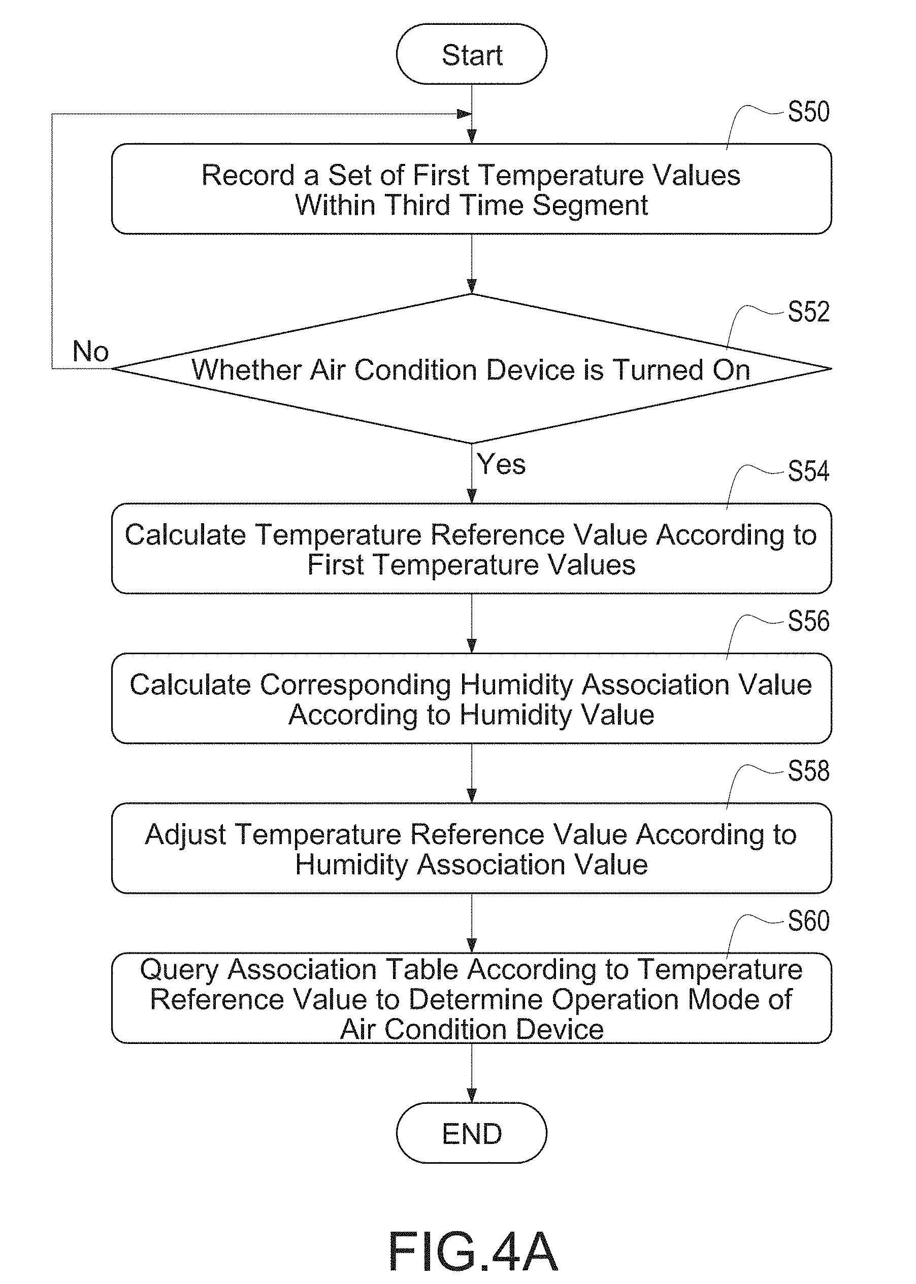
[0044] Please refer to FIG. 4A, which is an air condition device mode switch flowchart of the first embodiment. FIG. 4A illustrates an embodiment showing how the intelligent control device 1 selects a most fit operation mode for the air condition device 3 when the air condition device 3 is just started.
[0045] Before the air condition device 3 is not started, the intelligent control device 1 continuously senses and records a set of first temperature values (step S50) in a third time segments in the area. Specifically, the intelligent control device 1 regularly senses temperature data in the area with the multiple sensor beacons 2 or the temperature sensor unit and record these data to the data array. In this embodiment, the set of first temperature values include sufficient multiple temperature data corresponding to data amount necessary for the third time segment. The recording method for the set of third time segment is similar for recording the set of first time segment and thus it is not repeated here.
[0046] When the intelligent control device 1 senses and records the set of first temperature values, it is continuously determined whether the air condition device 3 is started (step S52). The air condition device 3 may be started by the control of the intelligent control device 1 or manually started by a user. Before the air condition device 3 is started, the intelligent control device 1 repeatedly performs the step S50 to update the set of first temperature values.
[0047] After the air condition device 3 is turned on, the intelligent control device 1 calculates an average value of the set of first temperature values to obtain a temperature reference value (step S54). In this embodiment, the intelligent control device 1 relies on the temperature reference value to determine the first operation mode to be used by the air condition device 3 after the air condition device 3 is started.
[0048] Please be noted that the humidity of the area affects feeling of users. For example, for high humidity, users may feel less than actual temperature and for low humidity, users may feel higher than actual temperature. As such, the intelligent control device 1 may selectively sense humidity value in the area via the multiple sensor beacons 2 or the temperature sensor unit to fine adjust the temperature reference value based on the sensed humidity value. For example, if the humidity value is larger than 60%, the temperature reference value is adjusted 2.degree. C. higher and if the humidity value is smaller than 20%, the temperature reference value is adjusted 2.degree. C. lower.
[0049] Specifically, the intelligent control device 1 firstly senses the humidity value in the area and calculates a humidity associated value (step S56). The intelligent control device 1 then adjusts the temperature reference value (step S58) according to the humidity associated value. Finally, the intelligent control device 1 queries a mode association table according to adjusted temperature reference value to determine an operation mode after the air condition device 3 is started (step S60).
[0050] In this embodiment, the mode association table may be downloaded from a cloud server (not shown) to the intelligent control device 1. The mode association table records a corresponding relation between the temperature reference value and multiple operation modes of the air condition device 3. The corresponding relation may be obtained based on history data, user habit and/or weather information gathered by a weather bureau. However, other methods may still be adopted.
[0051] For example, the mode association table may record that when the temperature reference value is larger than 25.degree. C., the air condition device 3 is operated in the cool mode, when the temperature reference value is smaller than 16.degree. C., the air condition device 3 is operated in a heating mode, and when temperature reference value is between 16.degree. C. and 25.degree. C., the air condition device 3 is operated in the fan mode. However, this is just an example, not to limit the invention scope.
[0052] Please refer to FIG. 4B, which illustrate operation mode switching flowchart of the air condition device according to a second embodiment. In FIG. 4B, it is shown how the intelligent control device 1 dynamically switches the operation mode of the air condition device 3 after the air condition device 3 is started.
[0053] After the air condition device 3 is started, the intelligent control device 1 senses and records a set of second temperature values (step S62) in the area in the fourth time segment. In this embodiment, the set of second temperature values contain sufficient temperature records satisfying necessary data amount for the fourth time segment. In addition, the set of second temperature values are recorded similar to the set of first temperature values and it is not repeated here again.
[0054] When the fourth time segment is passed, the intelligent control device 1 calculates an average value of the set of second temperature values to obtain a temperature compared value (step S64). In this embodiment, the temperature compared value refers to an average temperature in the area for the fourth time segment. Next, the intelligent control device 1 adjusts the operation mode of the air condition device 3 according to the temperature compared value (step S66).
[0055] After the step S66, the intelligent control device 1 determines whether the air condition device 3 is turned off (step S68). The intelligent control device 1 repeats the steps S62 to S66 before the air condition device 3 is turned off to continuously sense average temperature in the area and dynamically adjusts the operation mode of the air condition device 3 according to the average temperature.
[0056] Specifically, the intelligent control device 1 compare the temperature compared value with a predetermined temperature to determine whether the average temperature in the area is too hot, fine or too cold and further switches the operation mode of the air condition device 3 accordingly. For example, if the temperature compared value is larger than the predetermined temperature, the air condition device 3 is switched to the cool mode, and if the temperature compared value is smaller than the predetermined temperature, the air condition device 3 is switched to the fan mode. However, please be noted that these examples do not limit the invention scope.
[0057] In this embodiment, the predetermined temperature may be set by the intelligent control device 1 in advance, manually set by a manager or dynamically set by the intelligent control device 1 according to environment temperature in the area. These examples do not limit the invention scope.
[0058] Please refer to FIG. 5A and FIG. 5B, which illustrate predetermined temperature setting of the first embodiment and the second embodiment. As mentioned above, the predetermined temperature may not be a fixed value but dynamically set by the intelligent control device 1 according to environment temperature in the area. The embodiments in FIG. 5A and FIG. 5B respectively how the intelligent control device 1 dynamically set the predetermined temperature.
[0059] In FIG. 5A, the intelligent control device 1 may set an upper temperature, e.g. 30.degree. C. and a conversion temperature, e.g. 25.degree. C. When the environment temperature is larger than the upper temperature, the predetermined temperature is set as a minimum value, 20.degree. C. in this example, and the air condition device 3 is switched to the cool mode. By such, rapid cooling technical effect is achieved.
[0060] When the environment temperature is decreased and falling between the upper temperature and the first conversion temperature, e.g. between 25.degree. C. and 20.degree. C., the predetermined temperature is adjusted. In other words, the predetermined temperature is increased when the environment temperature is decreased. As such, the air condition device 3 is still operated in the cool mode.
[0061] When the area environment temperature is smaller than the first conversion temperature, the predetermined temperature is kept at a fixed temperature, e.g. 25.degree. C. in this example, and when the area environment temperature is smaller than the first conversion temperature which means the area is in comfortable zone, the predetermined temperature is not changed following the environment temperature. In such case, the air condition device 3 is switched to the fan mode.
[0062] In FIG. 5B, the intelligent control device 1 may set a second conversion temperature, e.g. 16.degree. C., and a bottom temperature, e.g. 12.degree. C. When the area environment temperature is larger than the second conversion temperature, the predetermined temperature is set as a standard value, 22.degree. C. in this example, and the air condition device 3 is operated in the fan mode.
[0063] When the area environment temperature is fallen within the second conversion temperature and the bottom temperature, the predetermined temperature is adjusted, 22.degree. C. to 28.degree. C. in this example. In other words, the predetermined temperature is increased when the area environment temperature is decreased. In such case, the air condition device 3 is switched to the heating mode.
[0064] When the area environment temperature is smaller than the bottom temperature, 12.degree. C. in this example, the predetermined temperature is kept at a fixed temperature, 28.degree. C. in this example. In addition, when the area environment temperature is smaller than the bottom temperature, the predetermined temperature is not changed following the environment temperature. In such case, the air condition 3 is kept operating in the heating mode.
[0065] As mentioned above, the intelligent control device may keep adjusting the air condition device continuously according to the area environment temperature to achieve a comfortable environment for users via the set of second temperature values sensing records and adjustment of predetermined temperature.
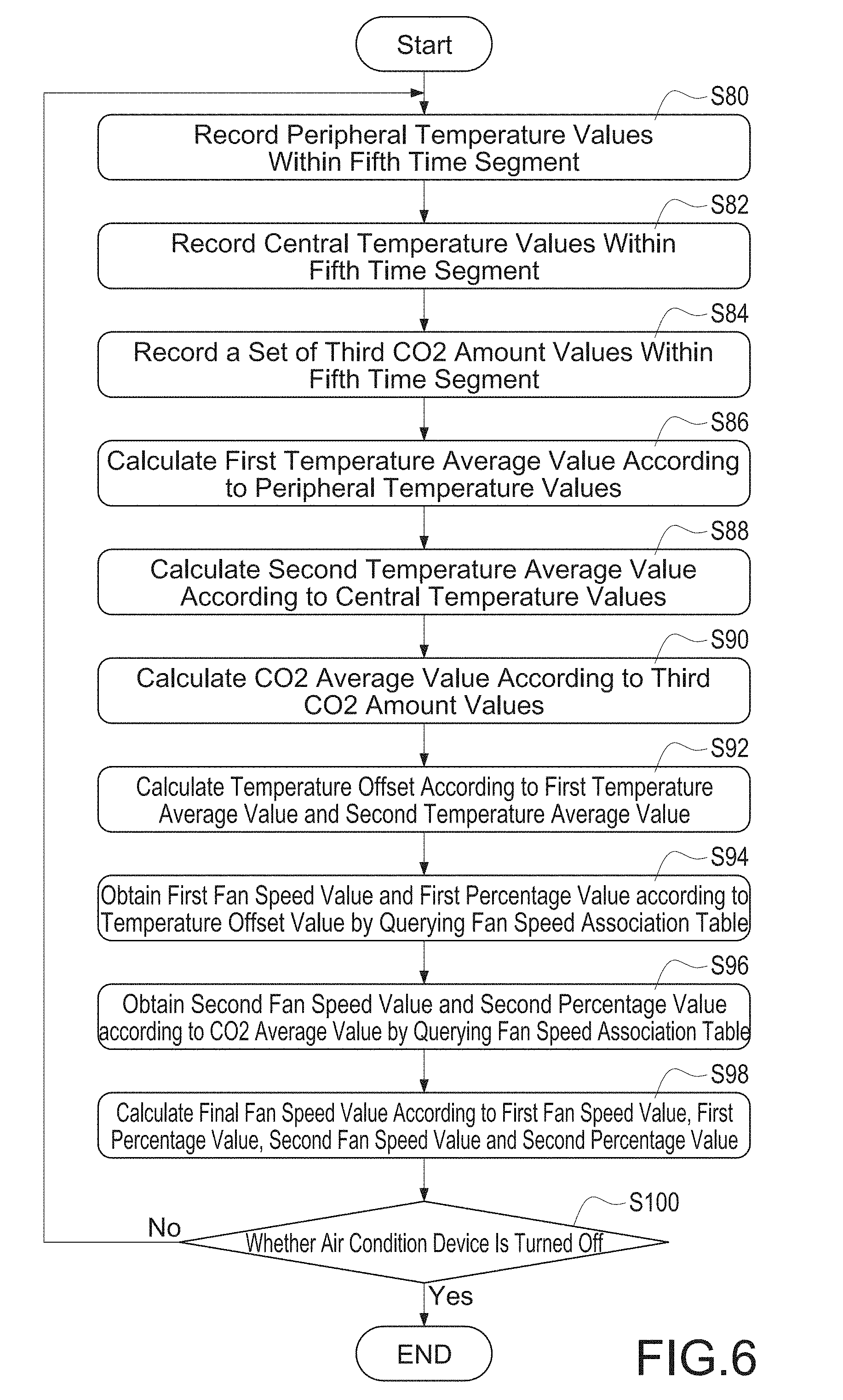
[0066] Please refer to FIG. 6, which is a fan speed adjustment flowchart of the first embodiment. The embodiment of FIG. 6 relates to how the intelligent control device 1 adjusts fan speed of the air condition device 3 dynamically after the air condition device 3 is started according to area environment parameters.
[0067] Firstly, the intelligent control device 1 senses and records a set of peripheral temperature values in the area for a fifth time segment with the multiple sensor beacons 2. In this embodiment, the multiple sensor beacons 2 are respectively disposed in peripheral sections of the area, and thus the sensed temperature data correspond to peripheral temperature status of the area. In addition, the set of peripheral temperature values contain sufficient multiple temperature records satisfying the record amount for the fifth time segment. The recording method for the set of peripheral temperature values is similar to the set of first temperature values and the set of second temperature values and thus it is not repeated here again.
[0068] The intelligent control device 1 further senses and records a set of central temperature values (step S82) in the area for the fifth time segment with the temperature sensor unit. In this embodiment, the intelligent control device 1 is mainly disposed at center position of the area, e.g. on a conference room table, and thus the sensed temperature data correspond to temperature status in the center section of the area. In addition, the set of central temperature values contain sufficient multiple temperature records satisfying the record amount for the fifth time segment. The recording method for the set of central temperature values is similar to the set of first temperature values and the set of second temperature values and thus it is not repeated here again.
[0069] The smart control device 1 further senses and records a set of third CO2 amount values in the area for the fifth time segment (step S84) with the CO2 sensor unit. In addition, the set of third CO2 amount values contain sufficient CO2 records satisfying the record amount for the fifth time segment. The recording method for the set of CO2 values is similar to the set of second CO2 values and thus it is not repeated here again.
[0070] Please be noted that the step S80, the step S82 and the step S84 may be performed concurrently and use the same fifth time segment.
[0071] After the fifth time segment, e.g. 3 minutes or 5 minutes, is passed, the intelligent control device 1 calculates the average value of the set of peripheral temperature values to obtain a first temperature average value (step S86), calculates the average value of set of the central temperature values to obtain a second temperature average value (step S88), and calculates the average value of the set of third CO2 amount values to obtain a CO2 average value (step S90). The steps S86, S88 and S90 may be performed in parallel and may not have order sequence relation among each other.
[0072] After the first temperature average value, the second temperature average value and the CO2 average value are calculated, the intelligent control device 1 calculates a temperature offset (step S92) in the area according to the first temperature average value and the second temperature average value. Specifically, the first temperature average value represents an average temperature in peripheral sections of the area for a passing time period, i.e. the fifth time segment, and the second temperature average value represents an average temperature in the central section of the area for the passing time period. Thus, a temperature offset between peripheral sections and central section of the area for the passing time period by minus the first temperature average value with the second temperature average value.
[0073] After the step S92, the intelligent control device 1 obtains a first fan speed value and a first percentage value (step S94) by querying a fan speed association table according to the temperature offset value. Meanwhile, the intelligent control device 1 further queries the fan speed association table according to the CO2 average value to obtain a second fan speed value and a second percentage value (step S96). The step S94 and the step S95 may be performed concurrently and may not have order sequence relation to each other.
[0074] Finally, the intelligent control device 1 calculates a final fan speed value (step S98) for controlling the air condition device 3 according to the first fan speed value, the first percentage value, the second fan speed value and the second percentage value. The intelligent control device 1 then determines whether the air condition device 3 is turned off (step S100) and repeats the step S80 to S98 before the air condition device 3 is turned off to continuously sense the temperature offset and CO2 amount in the area and to dynamically adjust the fan speed of the air condition device 3 to solve problems of large temperature offset or high CO2 amount.
[0075] Please be noted that the aforementioned fan speed association table may be stared in the intelligent control device 1 in advance or downloaded from a cloud server to the intelligent control device 1. In this embodiment, the fan speed association table records relation among the temperature offset, the first fan speed value, and the first percentage value and relation among the CO2 average value, the second fan speed value and the second percentage value.
[0076] An example of such fan speed association table is illustrated as follows:
TABLE-US-00001 Fan Speed Association Table first fan first CO2 second fan second temperature speed percentage average speed percentage offset value value value value value 1.degree. C. 20% 40% >600 ppm 20% 40% 2.degree. C. 50% 60% >800 ppm 40% 60% More than 100% 80% >1000 80% 80% 3.degree. C. ppm >1500 100% 100% ppm
[0077] In the table, if the intelligent control device 1 determines the current temperature offset is 2.degree. C., and the CO2 average value is larger than 1000 ppm, the query to the fan speed association table enables the intelligent control device 1 to obtain the final fan speed value as (50%*0.6)+(80%*0.8)=94%. In other words, the intelligent control device 1 generates a corresponding control command according to the final fan speed value and uses the control command to adjust the air condition device 3 for its fan speed. In this example, the air condition device 3 receives the control command and adjusts its fan speed to 94%.
[0078] Please be noted that if the intelligent control device 1 calculates a final fan speed value larger than 100%, the air condition device 3 still keeps its fan speed at 100%.
[0079] Please refer to FIG. 7, which illustrates a direction adjustment flowchart of the first embodiment. The embodiment of FIG. 7 shows how an intelligent control device 1 dynamically adjusts the fan direction of the air condition device 3, i.e. the fan swift direction, according to environment parameters of the area after the air condition device 3 is started.
[0080] During the air condition device 3 is operated, it mainly adjusts its fan direction according to a predetermined cycling pattern. When the intelligent control device 1 calculates the temperature offset value and the CO2 average value according to the technical solution of FIG. 6, the intelligent control device 1 may further determines whether the temperature offset value or the CO2 average value is larger than a threshold value (step S110). If the temperature offset value or the CO2 average value is larger than the threshold, the intelligent control device 1 adjusts the fan direction of the air condition device 3 to make its fan direction facing to a specific direction (step S112).
[0081] For example, if the temperature offset value is larger than the threshold value and the first temperature average value is larger than the second temperature average value, it means that the peripheral temperature is larger than the central temperature. In such case, the intelligent control device 1 instructs the air condition device 3 to adjust its fan direction towards peripheral sections of the area, i.e. where the multiple sensor beacons 2 are disposed to decrease the temperature offset value.
[0082] In another example, if the CO2 average value is larger than the threshold value, it means that there are many users in the area and these users are gathered around the intelligent control device 1 and thus the CO2 amount around the intelligent control device 1 does not lower down. In such case, the intelligent control device 1 may instruct the air condition device 3 to adjust its fan direction to the central section of the area, i.e. where the intelligent control device 1 is disposed, to make the CO2 in the central section of the area may evenly move to other places in the area to decrease the CO2 average value.
[0083] In another example, the intelligent control device 1 may record the positions of the multiple sensor beacons 2 in advance, and respectively compares the temperature data of the temperature sensor unit and temperature data of each sensor beacon 2. When a specific sensor beacon 2 reports an over high sensed temperature and temperature offset between the sensed temperature of the specific sensor beacon 2 and the sensed temperature of the temperature sensor unit is larger than a threshold value, the intelligent control device 1 may instruct the air condition device 3 to adjust its fan direction to the position where the specific sensor beacon 2 is disposed so that to decrease the temperature offset between the disposed position and other positions.
[0084] After the step S112, the intelligent control device 1 determines whether the situation is excluded, i.e. the case that the temperature offset is too large or the CO2 average value is too large (step S114). If the answer is no, the intelligent control device 1 further determines whether a predetermined time period is passed (step S116), and continuously determines whether the situation is excluded before the predetermined time period is passed.
[0085] If the temperature offset value or the CO2 average value is decreased or the predetermined time period is passed but the situation is still not excluded, the intelligent control device 1 controls the fan direction of the air condition device 3 to recover the fan direction to the predetermined cycle pattern (step S118). In addition, the intelligent control device 1 determines whether the air condition device 3 is turned off, and repeats the step S110 to the step S118 before the air condition device 3 is turned off and continuously adjust the fan direction of the air condition device 3.
[0086] Please be noted that if the air condition device 3 is adjusted for its fan direction but the situation is still not excluded after the predetermined time period, the intelligent control device 1 concludes it is a special case, e.g. the specific direction is a window or a position for disposing a heating equipment. Therefore, after the predetermined time period, no matter whether the situation is excluded, the intelligent control device 1 recovers the air condition device 3 to the predetermined cycle pattern.
[0087] In addition, as mentioned above, the intelligent control device 1 may further include a PM2.5 sensor unit and a TVOC sensor unit. In this example, the intelligent control device 1 may directly control the air condition device 3 to adjust its fan direction toward the position where the intelligent control device 1 is disposed, i.e. the central position of the area, when the PM2.5 or TVOC amount is too high or over a dangerous value. After the PM2.5 or TVOC amount in the central position of the area is decreased, the air condition device 3 is recovered to its original cycle pattern. By such, it prevents danger when too many users area gather around the intelligent control device 1.
[0088] Please be noted that the intelligent control device 1, as mentioned above, may also have an image capture unit (not shown). In an example, the intelligent control device 1 may capture biological feature of a person and performs identity recognition with the image capture unit to determine whether there is a person entering the area. As such, the intelligent control device 1 may determine a person entering the area and control the air condition device 3 to turn on.
[0089] Specifically, it cannot solve the problem when users forget to turn off luminaire devices if simply relying on checking turn-on and turn-off information of the luminaire devices to control the air condition device 3. If simply relying on CO2 amount to control the air condition device 3, it is not able to determine whether there is actually a person in the area, e.g. a pet may also change CO2 amount in the area. Therefore, by accompanying use of the image capture unit, the intelligent control device 1 may provide a more accurate control.
[0090] In this embodiment, the intelligent control device 1 may further upload the biological feature of a person to a cloud server to perform identity recognition of the person. As such, the intelligent control device 1 may recognize the identity of the person. As such, if there are multiple intelligent control devices 1 disposed in the building 60 and these intelligent control devices 1 are equipped with the image capture unit, a manager may know positions of all people via the cloud server.
[0091] Please refer to FIG. 8, which is a testing flowchart for the air condition device of the first embodiment. In this embodiment, the multiple sensor beacons 2 include a pressure sensor for sensing pressure values and a sound sensor for sensing sound information. FIG. 8 illustrates a technical solution in which multiple sensor beacons 2 are disposed inside the container body of the air condition device 3 to sense the pressure value and sound information to test whether the air condition is damaged.
[0092] Firstly, the intelligent control device 1 may automatically set or manually set by a manager for a testing period, e.g. 12 am midnight. In this example, the testing time means no user uses the air condition device 3.
[0093] The intelligent control device 1 continuously determines whether the testing time period is reached (step S130). If the testing time period is reached, the air condition device 3 is automatically turned on and the air condition device 3 is controlled to enter a testing mode (step S132). In the testing mode, the air condition device 3 is set to run with a fixed fan speed (step S134).
[0094] Then, the intelligent control device 1 uses the multiple sensor beacons 2, i.e. the pressure sensors, to respectively sense inner and outer pressure values inside and outside the container body of the air condition device 3 to calculate a pressure offset value (step S136). Meanwhile, the intelligent control device 1 uses the multiple sensor beacons 2, i.e. the sound sensors, to detect sound information inside the container body of the air condition device 3 (step S138). The step S136 and the step S138 may be performed at the same time, and there is no limitation on their sequence order for execution.
[0095] Then, the intelligent control device 1 compares the pressure offset value and the sound information with threshold values set during manufacturing (step S140) to determine whether the air condition device 3 is abnormal (step S142). Specifically, the threshold values during manufacturing record pressure values inside the container body and outside the container body and sound information inside the container body running at the fixed fan speed when the air condition device 3 is manufactured. By comparing of step S140, the intelligent control device 1 determines whether the motor of the air condition device 3 is abnormal, blocking in the filter or hardware driving program error.
[0096] If abnormal situation is found during the step S142, the intelligent control device 1 sends out a warning message (step S144), e.g. sending a warning message to the cloud server or a mobile device 4 owned by a manager. These examples do not limit the invention scope. At last, after the testing mode is completed, the intelligent control device turns off the air condition device 3 (step S146).
[0097] With the embodiment of FIG. 8, the intelligent control device 1 may regularly test the air condition device 3 to save man power and cost for regularly performing maintenance.
[0098] Please refer to FIG. 9, which is an intelligent control system diagram of the second embodiment. FIG. 9 illustrates an embodiment how the mobile device 4 and the intelligent control device 1 to communicate with each other.
[0099] The mobile device 4 is carried by a user for detecting user information of the user, e.g. body temperature or heartbeats. Specifically, the mobile device 4 is a smart phone or a smart watch capable of sensing user information. These examples do not limit the invention scope.
[0100] In this embodiment, the mobile device 4 is installed with an app (Application Program) 40. The mobile device 4 uses the app 40 to wirelessly connect to the intelligent control device 1 to transmit the user information to the intelligent control device 1. In addition, the mobile device 4 may use the app 40 to provide a motion sensor feedback interface and use the motion sensor feedback interface to receive an input of the user, e.g. too hot or too cold. In addition, the app 40 may transmit the feedback information to the intelligent control device 1.
[0101] When the user is located in the area, the intelligent control device 1 may wireless connect to the mobile device 4 and uses the app 40 to receive the user information and the feedback information. As such, the user body condition may be used as one of environment parameters. In a preferred embodiment, the intelligent control device 1 may adjust the third time segment and the fourth time segment for the embodiments of FIG. 4A and FIG. 4B according to the user information and the feedback information. As such, the mode switching time of the air condition device 3 may be adjusted to make the user feel more comfortable.
[0102] On the other hand, the mobile device 4 may also connect to a customer service system 7 via a network system. When the user finds the intelligent control system having any problem, the app 40 may be used for sending a query message to the customer service system 7. The query message, for example, may include the number of locations of the intelligent control system and abnormal situations occurred.
[0103] A maintenance person may receive the query message from the app 40 via the customer service system 7 and connects to the corresponding intelligent control device 1 via the network system to check and fix the abnormal situation reported by the user. As such, the maintenance person does not need to move to the real place to check the intelligent control system to effectively lower man cost.
[0104] Please refer to FIG. 10, which illustrate a position detection flowchart of the first embodiment. FIG. 10 illustrates an embodiment how the intelligent control device 1 uses the mobile device 4 to determine the position of the user.
[0105] In this example, the mobile device 4 contains a Bluetooth transmission unit support BLE function and the Bluetooth transmission unit has an unique Media Access Control (MAC) address.
[0106] When the user tries to connect to the intelligent control device 1 or the customer service system 7, the app 40 is activated on the mobile device (step S150). When the app 40 is activated, it automatically turns on the Bluetooth transmission unit in the mobile device 4 (step S152). Meanwhile, if the mobile device 4 is located in any wireless transmission range of any intelligent control device 1 in the building 60, the intelligent control device 1 detects the existence of the mobile device 4 (step S154) and retrieves the MAC address of the Bluetooth transmission unit of the mobile device 4.
[0107] In this example, the intelligent control device 1 is disposed in a specific area, like a factory, a warehouse, or a server room, and records all MAC addresses of Bluetooth transmission units of the mobile devices 4 that are allowed to enter the specific area, i.e. all users allowed to enter the specific area). After the step S154, the intelligent control device 1 determines whether the mobile device 4, i.e. the user, is allowed to appear at the specific area (step S156) according to the retrieved MAC address.
[0108] If the intelligent control device 1 determines that the mobile device 4 is not allowed to appear at the specific area, i.e. the intelligent control device 1 does not record the MAC address, the intelligent control device 1 sends out a warning message (step S158), e.g. sending the message to a cloud server or a mobile device 4 of a manager.
[0109] On the other hand, if the intelligent control device 1 determines that the mobile device 4 is allowed to appear in the specific area, the intelligent control device 1 establishes a connection to the mobile device 4 via BLE function (step S160). As such, the user uses the mobile device 4 and the app 40 to check information of the intelligent control device 1, the multiple sensor beacons 2 and the air condition device 3.
[0110] The foregoing descriptions of embodiments of the present invention have been presented only for purposes of illustration and description. They are not intended to be exhaustive or to limit the present invention to the forms disclosed. Accordingly, many modifications and variations will be apparent to practitioners skilled in the art. Additionally, the above disclosure is not intended to limit the present invention. The scope of the present invention is defined by the appended claims.
* * * * *
D00000
D00001
D00002
D00003
D00004
D00005
D00006
D00007
D00008
D00009
D00010
D00011
XML
uspto.report is an independent third-party trademark research tool that is not affiliated, endorsed, or sponsored by the United States Patent and Trademark Office (USPTO) or any other governmental organization. The information provided by uspto.report is based on publicly available data at the time of writing and is intended for informational purposes only.
While we strive to provide accurate and up-to-date information, we do not guarantee the accuracy, completeness, reliability, or suitability of the information displayed on this site. The use of this site is at your own risk. Any reliance you place on such information is therefore strictly at your own risk.
All official trademark data, including owner information, should be verified by visiting the official USPTO website at www.uspto.gov. This site is not intended to replace professional legal advice and should not be used as a substitute for consulting with a legal professional who is knowledgeable about trademark law.