Alignment Guide For Golf Clubs
Sanyal; Vikash ; et al.
U.S. patent application number 15/897091 was filed with the patent office on 2019-01-24 for alignment guide for golf clubs. The applicant listed for this patent is BrainStorm Golf, Inc.. Invention is credited to Vikash Sanyal, Jeffrey D. Sheets.
| Application Number | 20190022482 15/897091 |
| Document ID | / |
| Family ID | 65014646 |
| Filed Date | 2019-01-24 |


View All Diagrams
| United States Patent Application | 20190022482 |
| Kind Code | A1 |
| Sanyal; Vikash ; et al. | January 24, 2019 |
ALIGNMENT GUIDE FOR GOLF CLUBS
Abstract
Apparatus and methods are described herein to provide a golf club, such as, for example, a putter, with one or more site alignment members coupled to the head of the golf club. The site alignment member(s) can include markings or patterns visible to a golfer that can be used to aid the golfer with alignment of the golf club relative to a ball or target. An alignment guide housing can be used to couple a selected site alignment member to a club head of a golf club.
| Inventors: | Sanyal; Vikash; (Valley Center, CA) ; Sheets; Jeffrey D.; (Buda, TX) | ||||||||||
| Applicant: |
|
||||||||||
|---|---|---|---|---|---|---|---|---|---|---|---|
| Family ID: | 65014646 | ||||||||||
| Appl. No.: | 15/897091 | ||||||||||
| Filed: | February 14, 2018 |
Related U.S. Patent Documents
| Application Number | Filing Date | Patent Number | ||
|---|---|---|---|---|
| 15008269 | Jan 27, 2016 | |||
| 15897091 | ||||
| 62459014 | Feb 14, 2017 | |||
| 62467756 | Mar 6, 2017 | |||
| 62219040 | Sep 15, 2015 | |||
| 62108484 | Jan 27, 2015 | |||
| Current U.S. Class: | 1/1 |
| Current CPC Class: | A63B 53/0437 20200801; A63B 53/0441 20200801; A63B 53/0487 20130101; A63B 2053/0491 20130101; A63B 53/007 20130101; A63B 53/025 20200801; A63B 53/065 20130101; A63B 60/52 20151001 |
| International Class: | A63B 53/06 20060101 A63B053/06 |
Claims
1. A golf putter, comprising: a putter head defining a top surface, a face, a rear portion separated from the face by the top surface, and an alignment guide housing wherein the alignment guide housing defines a slot; a hosel received by the putter head; a shaft attachable to the hosel; and a site alignment member having a top surface including one or more alignment markings to facilitate alignment of the golf putter during use, a bottom surface opposite the top surface, and an attachment member protruding from the bottom surface wherein the attachment member is configured to be removably received by the slot of the alignment guide housing.
2. The golf putter of claim 1 wherein the golf club includes one or more weighting screws received by the putter head.
3. The golf putter of claim 1 wherein the alignment guide housing defines a cutout portion in an upper surface of the slot wherein the top surface covers the cutout portion when the attachment member of the site alignment member is received within the slot.
4. The golf putter of claim 3 further including a guide screw configured to be received in an opening of a rear surface of the alignment guide housing.
5. The golf putter of claim 1 wherein the rear portion further includes a pair of curved portions extending rearward relative to the putter head.
6. The golf putter of claim 1 further including one or more bushings configured to adjust a position at which the hosel is received by the putter head and thereby adjust an offset distance between the face and the hosel.
7. The golf putter of claim 1 further including a lie angle shim coupled to the hosel wherein the lie angle shim is configured to adjust a lie angle of the golf club putter.
8. A site alignment member for a golf putter, the site alignment member comprising: a substantially planar member defining a top surface; a bottom surface; and an attachment member protruding from the bottom surface; wherein the attachment member is configured to be received by the golf putter and wherein the site alignment member facilitates alignment of the golf putter during use.
9. The site alignment member of claim 8 further including one or more alignment markings upon the top surface.
10. A golf putter head assembly, comprising: a putter head defining a top surface, a face, a rear portion separated from the face by the top surface, and an alignment guide housing wherein the alignment guide housing defines a slot; a hosel received by the putter head; and a site alignment member having a top surface including one or more alignment markings to facilitate alignment of a golf putter, a bottom surface opposite the top surface, and an attachment member wherein the attachment member is configured to be removably received by the slot of the alignment guide housing.
11. The golf putter assembly of claim 10 wherein the rear portion further includes a closed arc portion extending rearward relative to the putter head.
12. The golf putter assembly of claim 10 wherein the attachment member protrudes from the bottom surface.
13. The golf putter assembly of claim 10 further including a guide screw configured to be received in an opening of a rear surface of the alignment guide housing.
14. The golf putter assembly of claim 10 further including one or more bushings configured to adjust a position at which the hosel is received by the putter head and thereby adjust an offset distance between the face and the hosel.
15. The golf putter assembly of claim 10 further including a lie angle shim coupled to the hosel wherein the lie angle shim is configured to adjust a lie angle of the golf club putter.
Description
CROSS-REFERENCE TO RELATED APPLICATIONS
[0001] This application claims priority to, and the benefit of, U.S. Provisional Application No. 62/459,014, filed Feb. 14, 2017, entitled "Alignment Guide for Golf Clubs", and U.S. Provisional Application No. 62/467,756, filed Mar. 6, 2017, entitled "Alignment Guide for Golf Clubs", the disclosures of which are incorporated herein by reference in their entirety. This application is a continuation-in-part of U.S. patent application Ser. No. 15/008,269, entitled "Site Alignment Device for Golf Clubs", filed on Jan. 27, 2016, which claims priority to U.S. Provisional Application No. 62/219,040, entitled "Site Alignment Device for Golf Clubs, filed Sep. 15, 2015 and U.S. Provisional Application No. 62/108,484, entitled "Adjustable Golf Club with Alignment Cover," filed on Jan. 27, 2015, the disclosures of which are incorporated herein by reference in their entirety.
BACKGROUND
[0002] It is well known that the game of golf requires players to carefully align a golf putter when attempting to putt a golf ball into the hole from a position on or nearby a golf green. To achieve proper alignment, a player may envision an imaginary path between the player's ball on the green and the hole. The player then attempts to align the putter such that the ball will follow the imagined path when the player actually putts the ball with the player's putter. Unfortunately, the visual appearance of many existing putters makes it difficult for players to properly align them such that the ball travels into or near the hold when putted.
SUMMARY
[0003] Apparatus and methods are described herein to provide a golf club, such as, for example, a putter, with one or more site alignment members coupled to the head of the golf club. The site alignment member(s) can include markings or patterns visible to a golfer that can be used to aid the golfer with alignment of the golf club relative to a ball or target. An alignment adapter platform can be used to couple a selected site alignment member to a club head of a golf club. Alternatively, the golf club head may define a slot or nest configured to receive an attachment plate of the site alignment member.
[0004] In one aspect the disclosure relates to a golf putter including a putter head defining a top surface, a face and a rear portion separated from the face by the top surface. The rear surface defines a slot or nest. The golf putter further includes a hosel received by the putter head and a shaft attachable to the hosel. A site alignment member is configured to be received by the slot and to facilitate alignment of the golf putter during use.
[0005] In another aspect the disclosure pertains to a site alignment member for a golf putter. The site alignment member includes a substantially planar member defining a top surface and an attachment plate configured to be coupled to the golf putter. The site alignment member facilitates alignment of the golf putter during its use.
[0006] The disclosure also relates to a golf putter including a putter head defining a top surface, a face, and a rear portion separated from the face by the top surface. The golf putter further includes an alignment guide housing wherein the alignment guide housing may be defined by the face and includes a slot. The golf putter further includes a hosel received by the putter head, a shaft attachable to the hosel, and a site alignment member. The site alignment member includes a top surface including one or more alignment markings to facilitate alignment of the golf putter during use, a bottom surface opposite the top surface, and an attachment member protruding from the bottom surface. The attachment member may be configured to be removably received by the slot of the alignment guide housing.
[0007] The disclosure is also directed to a site alignment member for a golf putter for facilitating alignment of a golf putter during use. The site alignment member includes a substantially planar member defining a top surface, a bottom surface and an attachment member protruding from the bottom surface. The attachment member is configured to be received by the golf putter and wherein the site alignment member.
[0008] In a further aspect the disclosure is directed to a golf putter head assembly including a putter head defining a top surface, a face, and a rear portion separated from the face by the top surface. A hosel is received by the putter head. An alignment guide housing defines a slot for receiving a site alignment member. The site alignment member may have a top surface including one or more alignment markings to facilitate alignment of a golf putter, a bottom surface opposite the top surface, and an attachment member configured to be removably received by the slot of the alignment guide housing.
BRIEF DESCRIPTION OF THE DRAWINGS
[0009] FIGS. 1A and 1B are side views and FIG. 1C is a top view of an adjustable putter, according to an embodiment.
[0010] FIG. 2A is a side view of a portion of the adjustable putter of FIGS. 1A-1C; and FIG. 2B is an enlarged view of detail A in FIG. 2A.
[0011] FIG. 3 is a side view of a portion of an adjustable putter, according to another embodiment.
[0012] FIGS. 4A and 4B are partially exploded perspective views of a putter having an adjustable face, according to another embodiment.
[0013] FIG. 5A is an exploded view of a portion of a putter having an adjustable lie angle, according to an embodiment.
[0014] FIG. 5B is a perspective view of a hosel of the putter of FIG. 5A.
[0015] FIG. 5C is a rear view of the putter of FIG. 5A.
[0016] FIG. 5D and 5E are front and rear views, respectively, of a hosel shim of the putter of FIG. 5A.
[0017] FIGS. 6A-6C are each a rear view of an adjustable hosel shown in different lie angle configurations.
[0018] FIG. 7 is an illustration of a disassembled adjustable hosel system, according to an embodiment.
[0019] FIG. 8 is a perspective view of a portion of a putter having an adjustable hosel, according to an embodiment.
[0020] FIG. 9A is top view of a hosel and bushings for a putter having an adjustable lie angle, according to an embodiment, and FIG. 9B is a detail view of a portion of the hosel system of FIG. 9A.
[0021] FIGS. 10A-10C illustrates schematic front views of a hosel and bushing for a putter having an adjustable lie angle, according to an embodiment.
[0022] FIGS. 11A-11C illustrates schematic rear views of a hosel and busing for a putter having an adjustable lie angle, according to another embodiment.
[0023] FIG. 12 is a rear perspective view of a portion of a putter, according to an embodiment.
[0024] FIG. 13 is an exploded side perspective view of the putter of FIG. 12.
[0025] FIG. 14 is a perspective view of a hosel shim of the putter of FIG. 12.
[0026] FIGS. 15A-15C each illustrate a portion of a hosel shim according to a different embodiment, shown in an orientation for a right handed user.
[0027] FIGS. 16A-16C each illustrate the portion of a hosel shim according to the different embodiments of FIGS. 15A-15C, shown in an orientation for a left handed user.
[0028] FIGS. 17A-17C each illustrate a bottom perspective view of the hosel shims of FIGS. 15A-15C, respectively.
[0029] FIG. 18 is a rear view of a portion of a putter, according to another embodiment.
[0030] FIG. 19 is an exploded side perspective view of the putter of FIG. 18.
[0031] FIG. 20 is a partially exploded rear perspective view of the putter of FIG. 18.
[0032] FIG. 21 is an exploded view of the hosel and hosel shim of the putter of FIG. 18.
[0033] FIG. 22 is a rear view of the hosel shim of the portion of the putter of FIG. 18.
[0034] FIG. 23 is an exploded view of a portion of the putter of FIG. 18.
[0035] FIG. 24A illustrates the hosel and hosel shim of the putter of FIG. 18 shown in an orientation for a right handed user; and FIG. 24B illustrates the hosel and hosel shim of the putter of FIG. 18 shown in an orientation for a left handed user.
[0036] FIG. 25A-25C are each a schematic illustration of a portion of a putter showing the adjustability of a shaft offset.
[0037] FIG. 26 is a rear view of a portion of a putter, according to another embodiment.
[0038] FIG. 27 is a top view of the putter of FIG. 26.
[0039] FIG. 28 is a rear view of the portion of the putter of FIG. 26 with a cover coupled thereto.
[0040] FIG. 29 is a top view of the portion of the putter of FIG. 26 with the cover of FIG. 28 coupled thereto.
[0041] FIG. 30 is a rear view and FIG. 31 is a top view of the cover of FIG. 28.
[0042] FIGS. 32 and 33 are each a rear view of an adjustable putter with a different embodiment of a cover with alignment markings.
[0043] FIGS. 34-36 are each a top view of an adjustable putter with a different embodiment of a cover with alignment markings.
[0044] FIG. 37 is a top view of an adjustable putter with alignment markings, according to an embodiment.
[0045] FIG. 38 is a top view of a portion of a putter, according to another embodiment.
[0046] FIG. 39 is a rear view of the portion of the putter of FIG. 38.
[0047] FIG. 40 is a rear view of a site alignment member, according to an embodiment.
[0048] FIGS. 41 and 42 are each a top view of a blank of a site alignment member, according to different embodiments.
[0049] FIGS. 43 and 44 are each a top view of a site alignment member, according to different embodiments.
[0050] FIGS. 45-48 are each a top view of a putter with a different embodiment of a site alignment member coupled thereto.
[0051] FIG. 49 is a top view of a putter with a site alignment member coupled thereto, according to another embodiment.
[0052] FIG. 50 is an exploded rear perspective view of a putter and a site alignment member, according to an embodiment.
[0053] FIG. 51A is a top view of the putter and site alignment member of FIG. 50, and FIGS. 51B and 51C are top views of two different alternative embodiments of a site alignment member.
[0054] FIG. 52 is an exploded rear perspective view of a putter and a site alignment member, according to an embodiment.
[0055] FIG. 53 is a perspective view of an alignment platform, according to an embodiment.
[0056] FIG. 54A is a top view of the putter and site alignment member of FIG. 52, and FIGS. 54B and 54C are top views of two different alternative embodiments of a site alignment member.
[0057] FIG. 55 is a rear perspective view of a putter and a site alignment member, according to an embodiment.
[0058] FIG. 56 is a bottom perspective view of the putter and site alignment member of FIG. 55.
[0059] FIG. 57A is a rear view of the site alignment member of FIG. 55 in an uncompressed configuration; and FIG. 57B is a rear view of the site alignment member of FIG. 55 in a compressed configuration.
[0060] FIG. 58A is a top view of the putter and site alignment member of FIG. 55, and FIGS. 58B and 58C are top views of two different alternative embodiments of a site alignment member.
[0061] FIG. 59 is a rear perspective view of a putter with a site alignment member coupled thereto with an alignment adapter platform.
[0062] FIG. 60 is an exploded rear perspective view of the putter and the alignment adapter platform of FIG. 59.
[0063] FIG. 61A is a top view of the putter and site alignment member of FIG. 59, and FIGS. 61A and 61B are top views of two different alternative embodiments of a site alignment member.
[0064] FIG. 62 is a rear perspective view of a putter with a site alignment member coupled thereto.
[0065] FIG. 63 is a bottom perspective view of the putter and the site alignment member of FIG. 62.
[0066] FIG. 64A is a top view of the putter and site alignment member of FIG. 62, and FIGS. 64A and 64B are top views of two different alternative embodiments of a site alignment member.
[0067] FIGS. 65A, 65B-69A, 69B, 69C, and 69D illustrate another embodiment of a golf club that can be adapted to have a site alignment member removably coupled thereto.
[0068] FIGS. 70-76 illustrate yet another embodiment of a golf club that can be adapted to have a site alignment member removably coupled thereto.
[0069] FIGS. 77A-77C and FIGS. 78A-78B are top views of alternative embodiments of site alignment members capable of being utilized with the golf clubs of FIGS. 65-76.
[0070] FIGS. 79A-79B, 80 and 81 illustrate an additional embodiment of a golf club that can be adapted to have a site alignment member removably coupled thereto.
[0071] FIGS. 82-83 illustrate yet another embodiment of a golf club that can be adapted to have a site alignment member removably coupled thereto.
DETAILED DESCRIPTION
[0072] Apparatus and methods are described herein to provide a golf club, such as, for example, a putter, with one or more site alignment members coupled to the head of the golf club. The site alignment member(s) can include markings or patterns visible to a golfer that can be used to aid the golfer with alignment of the golf club relative to a ball or target. An alignment adapter platform can be used to couple a selected site alignment member to a club head of a golf club. Alternatively, the golf club head may define a slot or nest configured to receive an attachment plate of the site alignment member.
[0073] In some embodiments a site alignment member may be used with an existing golf club or putter not otherwise designed to accommodate such an alignment aid. As is discussed below, in these embodiments the site alignment member may be secured by using an alignment adapter platform that is coupled, typically non-removably, to a golf club head or putter. This enables a user to select from multiple different site alignment members based upon the alignment markings associated of each and to easily interchange one for another using the alignment adapter platform.
[0074] While adoption of a removable cover may provide a more appealing appearance of the golf club to a golfer, the cover can also be used as a template for putter alignment. For example, alignment markings can be provided on the cover to help align the adjustable golf club during use. The cover can have a broad surface area that can provide a large pallet to place an assortment of different alignment lines to help golfers set up to their putts more accurately. While one alignment system may benefit one golfer it may take another different alignment system to satisfy another. Also, due to right eye versus left eye dominance, placement position of the ball, and/or each golfer having their own unique stance, each golfer may set up differently to the same alignment system. Thus, a variety of different alignment features can be offered to the golfer based on the system they find that works best for their particular set up. For example, alignment lines can be provided that can range from a single line to a multitude of lines offering several optic options for the golfer to choose from.
[0075] In other embodiments a site alignment member may be used with an adjustable golf club. One or more covers can be provided with an adjustable golf club a described herein. Various different covers with alignment features are described below. However, before proceeding with a discussion of various site alignment members and alignment covers, a description is first provided of exemplary adjustable golf clubs capable of being configured with site alignment members. It should be understood, however, that in other embodiments described herein site alignment members are provided for use with existing golf clubs, including putters, that are not otherwise adjustable or configurable and with golf putters especially adapted to receive site alignment members or particular configurations.
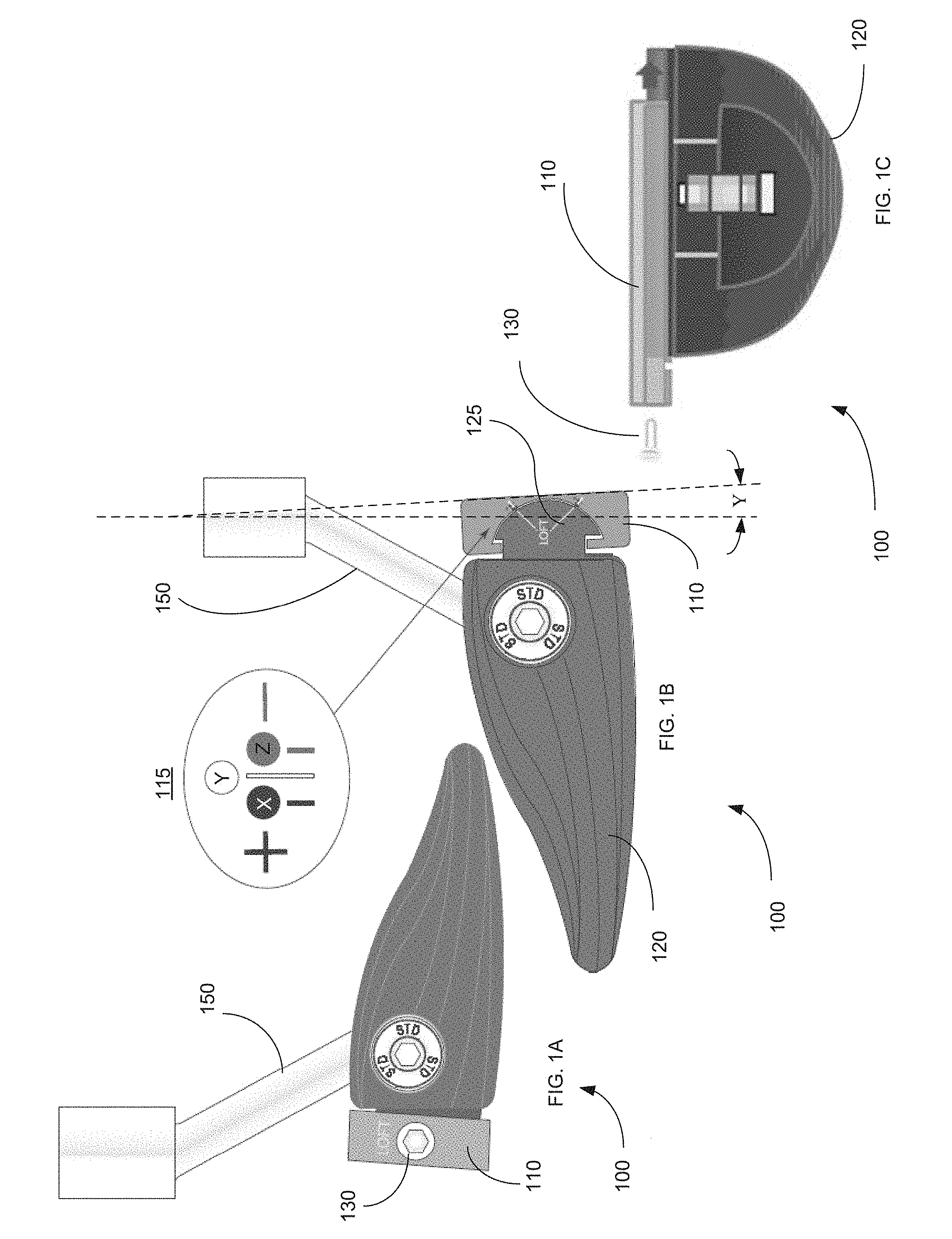
[0076] FIGS. 1A and 1B are side views of an adjustable putter 100, according to an embodiment. FIG. 1C is a top view of the putter 100. The putter 100 includes a face 110, a head 120 and a hosel 150. The hosel 150 can be coupled to the head 120 and used to couple the putter 100 to a shaft (not shown) of the putter. The angle of the face 110 relative to the head 120 of the putter 100 can be changed (as described in further detail herein) to adjust the loft angle of the putter 100. The loft angle can be adjusted over any suitable range, such as, for example, from -5.degree. to 15.degree.. In some embodiments, as described in further detail herein, discrete loft angles may be selectable. For example, the face 110 may be coupled to the head 120 such that the putter 100 has a 0.5.degree., 3.degree., or 5.5.degree. loft angle. In other embodiments, the loft angle may be continuously variable over any suitable range.
[0077] As shown in FIG. 1B, the face 110 of the putter 100 can include a scale 115 that can indicate a selected loft angle. For example, the head 120 can include a loft indicator 125 that can be aligned with a selected indicator "X" when the putter 100 has a loft angle of 5.5.degree., indicator "Y" when the putter 100 has a loft angle of 3.degree., and indicator "Z" when the putter 100 has a loft angle of 0.5.degree.. As shown, the putter 100 is in a "Y" configuration, having loft angle of 3.degree..
[0078] As shown in the top view of FIG. 1C, the face 110 can be slidably coupled to the head 120. In some embodiments, as described in further detail herein, the loft angle can be adjusted by removing and repositioning the face 110. For example, the face 110 can be coupled to the head 120 in multiple configurations. A bolt 130 can be used to couple the face 110 to the head 120, such that the face 110 can be fixed in position and the loft angle can be prevented from being inadvertently changed. In some such embodiments, the head 120 can include a stop (not shown) operable to prevent the face 110 from sliding past an edge of the head 120. In this way, the face 110 can be secured to the head 120 by a single bolt 130. For example, the stop can be disposed on an opposite edge of the head 120.
[0079] The face 110 can be constructed of high-strength plastic, steel, titanium, and/or any other suitable material. In some embodiments, the head 120 can be configured to be used with one of multiple faces having different characteristics. In other words, the putter 100 can have multiple different selectable faces 110 that can be coupled to the head 120. In some embodiments, the face 110 can be painted, pigmented (e.g., in the case where the face 110 is constructed of high-strength plastic), etched, and/or otherwise marked such that the user can determine the characteristics of the face. In some embodiments the face 110 may receive a variety of different face insert materials affecting characteristics such as, for example, feel, sound and roll. Moreover, surface finishes of the faces 110 (e.g., CNC milling, grooves, mirrored and textured) may also influence ball spin and provide a variety of cosmetic presentations.
[0080] FIG. 2A is a side view of a portion of the putter 100, and FIG. 2B is a detail view of a portion A of FIG. 2A, illustrating the face 110. As described above, the face 110 can be adjustably coupled to the head 120 of the putter 100.
[0081] In this embodiment, as shown, for example, in FIG. 2B, the face 110 includes grooves 112 that can receive a projection 122 of the head 120. In this embodiment, the face 110 includes two sets of three grooves 112, while the head 120 includes two projections 122, each projection 122 corresponding to a set of grooves 112. The loft angle of the putter 100 can be adjusted by selecting a groove 112 in which to dispose the projection 122. In other words, each groove 112 corresponds to a different selectable loft angle.
[0082] FIG. 3 depicts a side view of a portion of an alternative embodiment of a putter 200 including a head 220 and a face 210. In this embodiment, the putter 200 includes a single set of three grooves defined by the face 210, and a single corresponding projection on the head 220. In other embodiments the face 210 can have any number of grooves and/or the head 220 can include any number of projections. In addition or alternatively, the face 210 can include one or more projections and/or the head 220 can include one or more corresponding grooves.
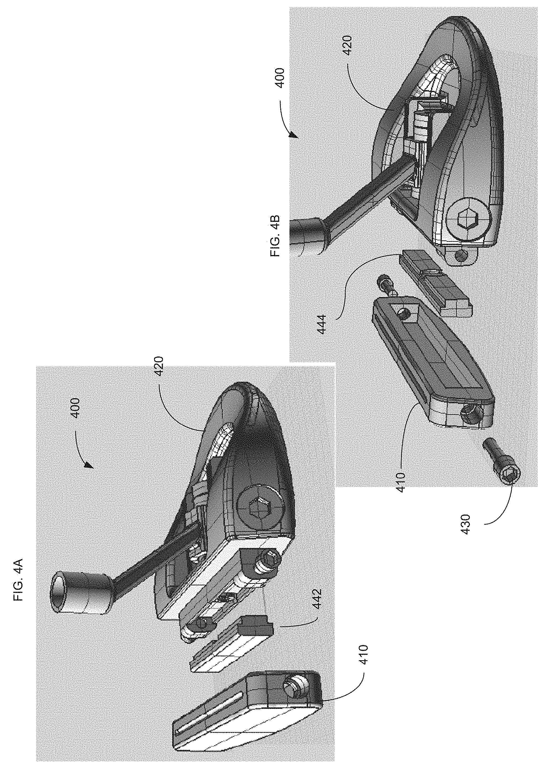
[0083] FIGS. 4A and 4B are partially exploded perspective views of a putter 400 having an adjustable loft angle, according to an embodiment. The putter 400 includes a face 410 and a head 420, each of which can be similar to the face 110 and the head 120 shown and described above. Bolts 430 can be used to couple the face 410 to the head 420.
[0084] In this embodiment, the loft angle of the putter 400 can be adjusted via a selected shim 442. The shim 442 can be coupled between the face 410 and the head 420 using for example, bolts 430. In some embodiments, a putter 400 can be provided with multiple different shims to selectively change the loft angle of the putter 400. The shim(s) 442 can have various different shapes, sizes, configurations, etc. to provide various different loft angles. For example, in some embodiments, a shim 442 can provide a particular loft angle, such as for example, a 3.degree. loft angle. In some embodiments a shim 442 can be reversible. For example, in such an embodiment, the shim 442 can be coupled to the head 420 and face in a first orientation or position to provide a first loft angle, and can be moved to a second orientation or position to provide a second loft angle. For example, in some embodiments, a shim 442 can provide the putter 400 with a 0.5.degree. loft angle when in a first position or orientation and can provide the putter 400 with a 5.degree. loft angle when in a second position or orientation. For example, in some such embodiments, the shim 442 can be coupled to the face 410 and head 420 in a first orientation to obtain the first loft angle, and can be coupled to the face 410 and head 420 in a reversed or rotated second position or orientation (e.g., rotated 180.degree.) to obtain the second loft angle. In other examples, a shim 442 can be used to set the loft angle to any suitable angle, such as between, for example, -5.degree. and 15.degree..
[0085] The putter 400 can be configured to be used with any number of selectable shims. For example, shims that can provide the putter 400 with various suitable loft angles can be disposed between the face 410 and the head 420. Shims can be constructed of any suitable material, such as steel, high-strength plastic, rubber, polymers, etc. Shims can also be provided having a particular a color or color marking that indicates the particular loft angle, or can otherwise be marked to indicate the loft angle to which they correspond. In some embodiments, multiple shims can be used to adjust the putter 400 to the desired loft angle. For example, multiple shims 442 can be coupled between the face 410 and the head 420 of the putter 400 to achieve a desired loft angle.
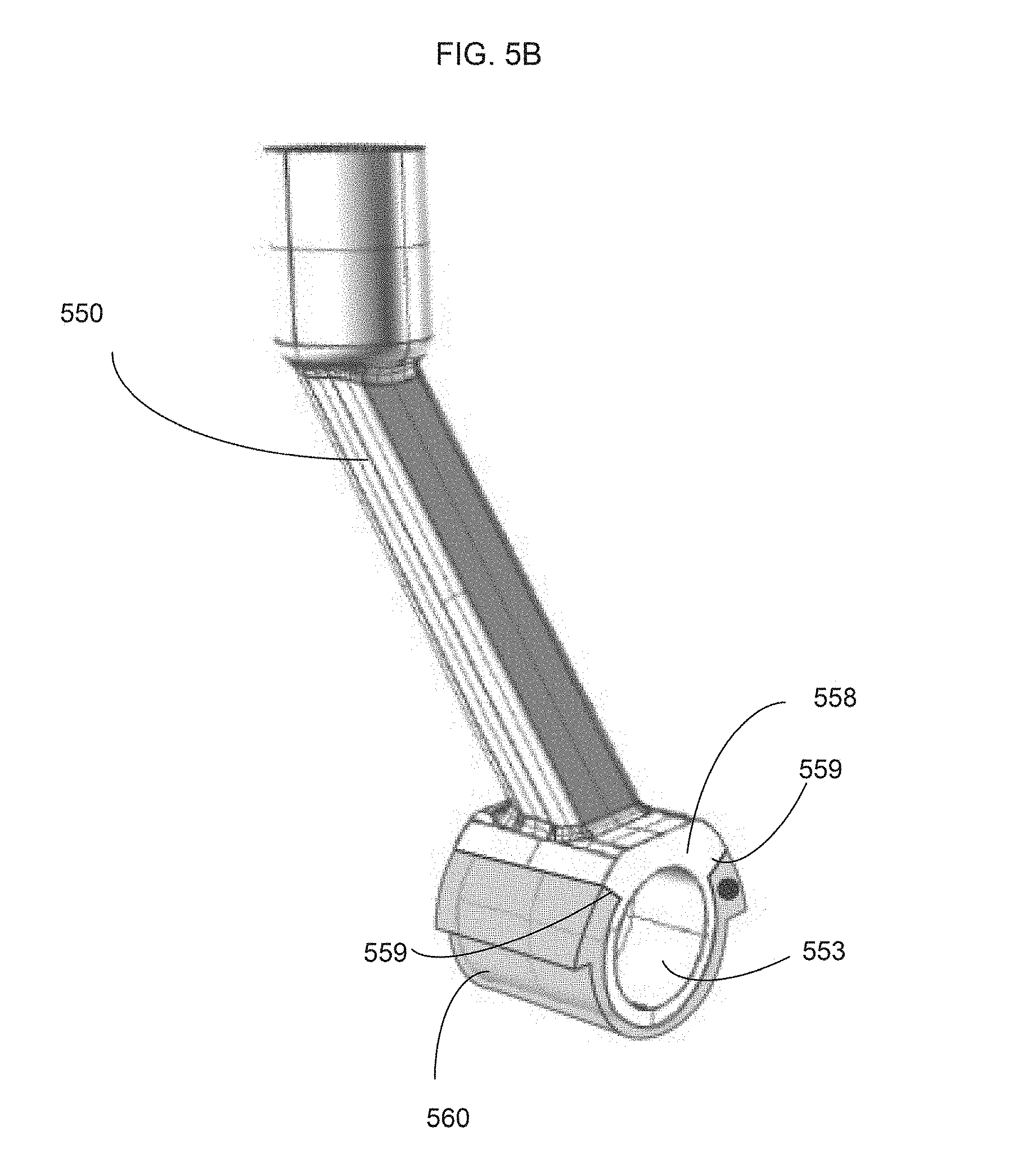
[0086] FIG. 5A is an exploded view of a portion of a putter 500, according to an embodiment. FIG. 5B is a perspective view of a hosel 550 of the putter 500 with a hosel shim 560 coupled thereto, and FIG. 5C is a rear view of the putter 500 (shown with the outer bushing 570 and hosel bolt 580 transparent for illustration purposes). The hosel 550 can be adjustably coupled to a head 520 of the putter 500 via a hosel shank 522 of the head 520 (see, e.g., FIGS. 5A and 5C). The hosel 550 includes a mounting portion 558 that defines a lumen or through-hole 553 (see, e.g., FIG. 5B) that can receive the hosel shank 522. A hosel shim 560 (also referred to as a "lie angle shim") can be disposed between the hosel 550 and the head 520 of the putter 500. The putter 500 further includes two bushings 570 and a hosel bolt 580. The bushings 570 can be used to position the hosel 550 on the hosel shank 522. The hosel bolt 580 can secure the hosel 550 to the head 520.
[0087] FIGS. 5D and 5E are front and rear views, respectively, of the shim 560. The hosel shim 560 has an inner perimeter 568 configured to cooperate with the mounting portion 558 of the hosel 550, and an outer perimeter portion 569 configured to cooperate with a retaining portion 529 (see, e.g., FIGS. 5A and 5C) of the head 520. The inner perimeter 568 of the hosel shim 560 can have a profile that matches a surface of the mounting portion 558 of hosel 550 such that the hosel shim 560 can be slid onto the mounting portion 558 of the hosel 550. When the hosel shim 560 is coupled to the mounting portion 558, surface portions 561 on the hosel shim 560 can contact corresponding surfaces 559 on the mounting portion 558 (see e.g., FIG. 5B) to prevent the hosel shim 560 from rotating relative to the hosel 550.
[0088] Similarly, the outer perimeter 569 of the hosel shim 560 can have a profile configured to contact a retaining portion 529 of the head 520. For example, the outer perimeter 569 can have a feature 579 (e.g., a shoulder, projection, notch, groove and/or other suitable structure) that can contact or engage a top edge portions 527 of retaining portion 529. In this way, the hosel shim 560 can be slidably coupled to the head 520, and the outer features 579 when engaged with the top edge portions 527 can help prevent the hosel shim 560 from rotating relative to the head 520. Thus, when the hosel 550 and the hosel shim 560 are collectively coupled to the head 520, rotational movement of the hosel 550 relative to the head 520 can be limited or prevented.
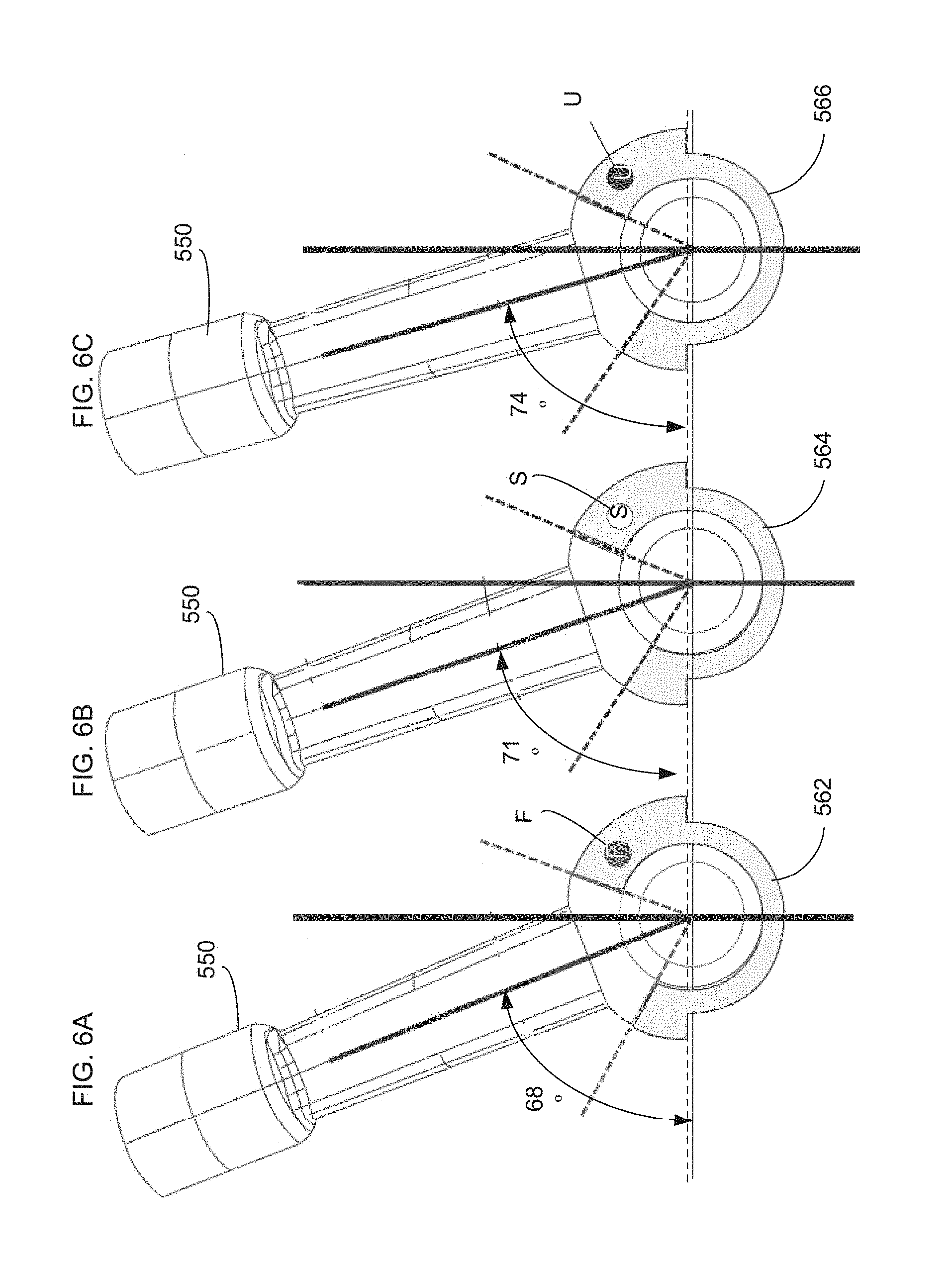
[0089] The hosel shim 560 can be used to set the lie angle L of the putter 520 (see, e.g., FIG. 5C). For example, each of FIGS. 6A-6C, illustrate the use of a different shim 562, 564 and 566, respectively, coupled to the hosel 550 to provide a different lie angle L for the putter 500. Thus, the putter 500 can be adjusted to have any suitable and/or desired lie angle. In some embodiments, the putter 500 can be adjusted to have a lie angle, between, for example, 57.degree. and 79.degree.. The hosel 550 can be reversed to change the putter 500 from a right handed putter to a left handed putter. In this way, the putter 500 can have an adjustable lie angle and an adjustable handedness using a single hosel 550 and interchangeable hosel shim 560.
[0090] For example, as shown in FIG. 5A, the hosel bolt 580 can be decoupled from the head 520 of the putter 500, which can allow the hosel 550 to be removed from the hosel shank 522 and the hosel shim 560 to be removed from the hosel 550. A hosel shim, such as, for example, one of the shims 560, 562, 564, or 566 can be coupled to the hosel 550. The hosel 550, including the selected hosel shim can be re-coupled to the head 520. The hosel shim can cooperate with the hosel 550 and/or the head 520 to fix the position of the hosel 550 relative to the head 520 when the hosel 550 is coupled to the head 520.
[0091] The hosel shims 560, 562, 564, 566 can be color coded and/or otherwise marked to indicate the lie angle of the putter based on the selected shim. For example, as shown in FIGS. 6A-6C the shims 562, 564, and 566 are each marked with an indication of the lie angle corresponding to that shim. Shim 562 is marked with an "F", which can indicate, for example, a flat lie angle, such as a flat lie angle of, for example, 68.degree.. Similarly, the shim 564 is marked with an "S", which can indicate, for example, a standard lie angle, such as a standard lie angle of, for example, 71.degree.. Furthermore, the shim 566 is marked with a "U", which can indicate an upright lie angle, such as an upright lie angle of, for example, 74.degree.. In some embodiments, the shim can include a numerical indicator corresponding to the particular lie angle associated with that shim. The hosel shims 560, 562, 564, 566 can be constructed of any suitable material, such as, for example, steel or high strength plastic.
[0092] FIG. 7 is an illustration of a disassembled adjustable hosel system, according to another embodiment. The adjustable hosel system 775 includes a hosel 750, a front hosel bushing (also referred to as a "hosel shim" or "lie angle shim") 762, a rear hosel bushing (also referred to as a "hosel shim" or "lie angle shim") 764, washers 766 and an alignment rod 770. The hosel 750, hosel bushings 762, 764, and washers 766 are operable to be slidably disposed over a hosel shank (which can be similar to the hosel shank 522 as shown and described with reference to FIG. 5A).
[0093] The hosel 750 can define hosel holes 755 and the hosel bushings 762, 764 can define bushing holes 765. The alignment rod 770 can be disposed through a select hosel hole 755 and corresponding select bushing hole 765. As shown in FIG. 8, when disposed on a hosel shank (not shown in FIG. 8) of a putter 700, the adjustable hosel system 775 can have a fixed rotational position. For example, the hosel 750 can be fixed relative to a head 720 of the putter 700 when the alignment rod 770 is disposed through a hosel hole 755. When the alignment rod 770 is removed from the hosel 750, the hosel 750 can rotate on the hosel shank. In this way, the hosel 750 can be rotated to align a select hosel hole 755 with a select bushing hole 765 to adjust the lie angle of the putter 700. After being aligned, the alignment rod 750 can be disposed within the hosel 750, locking the hosel 750 in position.
[0094] In some embodiments, the front hosel bushing 762 of the hosel 750 can include markings, such as color codes, etched markings, and/or other suitable indicators associated with the lie angle. For example, one hole can be marked by an "F" to indicate that the hosel will be at a flat lie angle relative to the head 720, a second hole can be marked by a "S," and a third hole can be marked with a "U" to indicate that the hosel 750 will be at a standard and upright lie angle, respectively, relative to the head 720.
[0095] A retaining bolt or nut (not shown in FIG. 8) can be coupled to the front bushing 762 and/or the alignment rod 770, and/or otherwise coupled to the head 720 to lock the alignment rod 770 and the lie angle in position. The hosel bushings 762, 764 can be constructed of any suitable material, such as, for example, steel, high-strength plastic, etc.
[0096] FIGS. 9A-9C illustrate a hosel system of an adjustable putter, according to another embodiment. FIG. 9A is a top view of a hosel 950, a first hosel bushing (also referred to as a "hosel shim" or "lie angle shim") 962, and a second hosel bushing (also referred to as a "hosel shim" or "lie angle shim") 966, according to another embodiment. FIG. 9B is a detail view of a portion of the hosel 950 and hosel bushings 962, 966 of FIG. 9A. The hosel 950 includes a set of grooves 952 and the first hosel bushing 962 includes a projection 963. The projection 963 of the first bushing 962 can be selectively disposed within a selected groove of the set of hosel grooves 952 to adjust the angle of the hosel 950 to the bushing 962. By adjusting the angle of the hosel 950 relative to the bushing 962, the lie angle of a putter can be adjusted. For example, as similarly shown and described above with reference to FIGS. 6A-6C, the bushing 962 can be operable to fix the position of the hosel 950 relative to a head of a putter. The projection 967 of the second bushing 966 can similarly be selectively disposed within a selected groove of a set of multiple grooves 964 defined by the first bushing 962 to further adjust the lie angle of the putter.
[0097] FIG. 10 is a schematic diagram of a hosel bushing 1060 having a projection (not shown) configured to be received by one of several grooves of a hosel 1050, 1055 in a similar manner as described above for other embodiments. FIG. 10 depicts a right handed hosel 1050 and a left handed hosel 1055. The projections and the grooves can be operable to prevent the hosel 1050, 1055 from rotating relative to the hosel bushing 1060 when coupled to a head of a putter. In some embodiments, the grooves can be disposed 3.5 degrees apart from each other. In this way, lie angles between, for example, 64.degree. to 81.degree. at 3.5.degree. increments can be selected. In other embodiments, the grooves of the hosel 1050, 1055 can be operable to allow any suitable lie angle and/or any suitable increments to be selected.
[0098] FIG. 11 is a schematic diagram of a hosel bushing 1160 and right and left handed hosels 1150, 1155, respectively, according to another embodiment. The hosel bushing 1160 and/or the hosels 1150, 1155 can be similar to the hosels and bushings shown and described with reference to FIG. 10, except as shown in FIG. 11, the hosels can have a single projection operable to lock the hosel into position at a selected lie angle.
[0099] FIGS. 12 and 13 illustrate a portion of an adjustable putter, according to another embodiment. A putter 1200 includes a head 1220 and a face 1210, which can be similar to, for example, the head 120 and face 110, respectively, described above. Bolts 1230 can be used to couple the face 1210 to the head 1220 in a similar manner as described above for putter 100. The head 1210 includes a hosel shank 1222 to which a hosel 1250 can be coupled. The hosel 1250 can be adjustably coupled to the head 1220 (via the hosel shank 1222) using a selected hosel shim (also referred to as a "lie angle shim") 1260 that can be used to adjust the lie angle of the putter 1200 as described in more detail below.
[0100] The hosel 1250 includes a mounting portion 1258 that defines a through-hole or lumen 1253 through which the hosel shank 1222 of the head 1220 can be received. The hosel 1250 also defines a threaded top opening 1257. The hosel shim 1260 defines a lumen or through-hole 1285 and can be coupled to the hosel 1250 with, for example, a set screw 1282. For example, the set screw 1282 can be received through the through-hole 1285 and the top opening 1257 of the hosel 1257 and terminate in contact with the hosel shank 1222. The mounting portion 1258 of the hosel 1250 includes a top mounting feature 1251 (see, e.g., FIG. 13) on which the hosel shim 1260 can matingly be coupled and which can be used to move the hosel 1250 relative to the head 1220 to set the putter 1200 at the desired lie angle as described in more detail below.
[0101] The putter 1200 further includes bushings 1270 (see, e.g., FIG. 13) and a hosel bolt 1280. The bushings 1270 can be used to position the hosel 1250 on the hosel shank 1222 (see, e.g., FIG. 13) of the head 1220, and can be adjusted to change the shaft offset of the putter 1200 as described in more detail below with reference to FIGS. 25A-25C. The hosel bolt 1280 can be received through the through-hole 1253 and a lumen of the hosel shank 1222 to secure the hosel 1250 to the head 1220. The hosel bolt 1280 can provide a threaded coupling to the hosel shank 1222. For example, the hosel bolt 1280 can include a threaded portion (not shown) configured to mate with a threaded portion (not shown) within the interior of the hosel shank 1222. Bolts 1272 can be used to add weight to the putter 1200. For example, the putter can include one or more sets of bolts 1272 each having a different weight. Thus, a user can selectively use a set of bolts 1272 to achieve a desired weight of the putter 1200.
[0102] In this embodiment, the hosel 1250 and hosel bushings 1270 can be coupled to the hosel shank 1222 of the head 1220, and then the hosel shim 1260 can be coupled to the hosel 1250 from above or from a vertical direction. For example, the hosel 1250 and bushings 1270 can be slid over the hosel shank 1222, and the hosel shim 1260 can be installed over the hosel 1250 after the hosel 1250 has been slid into position on the hosel shank 1222. The hosel bolt 1280 can be placed through an opening of the bushings 1270 and through the through-hole 1253 of the mounting portion 1258 of the hosel 1250. Although the bushings 1270 are shown disposed next to each other in the exploded view, the bushings 1270 can be reconfigured relative to the hosel 1250 to adjust a shaft offset of the putter 1200 as described in more detail below. For example, the bushings 1270 can be positioned such that one bushing 1270 is placed on the hosel shank 1222, then the hosel 1250 and then the other bushing 1270. Thus, a bushing 1270 is disposed on each side of the mounting portion 1258 of the hosel 1250. The bushings 1270 can also be arranged such that the hosel 1250 is placed on the hosel shank 1222 and then both bushings 1270.
[0103] As shown in FIG. 14, the shim 1260 defines an opening or though-hole 1285 and includes an interior surface 1283 having an angled surface portion 1284. The interior surface 1283 substantially corresponds to the mounting feature 1251 and a top portion of the mounting portion 1258 of the hosel 1250. When the hosel shim 1260 is disposed on the mounting portion 1258 of the hosel 1250, the angled surface portion 1284 mates with or contacts the mounting feature 1251 of the mounting portion 1258, and the hosel shim 1260 moves or rotates the hosel 1250 relative to the hosel shank 1222, thus positioning the hosel 1250 relative to the hosel shank 1222. The lie angle will be set based on the particular angle of the angled surface portion 1284. Thus, the hosel 1250 can rotate back and forth relative to the hosel shank 1222 until the hosel shim 1260 is placed in position on the hosel 1250. The set screw 1282 can then be installed from above or in a vertical direction through the opening 1285 of the shim 1260 and the through-hole 1257 of the hosel 1250, securing the hosel shim 1260 in position, and preventing movement or rotation of the hosel 1250. The hosel bolt 1280 can then secure the hosel 1250 to the head 1220.
[0104] As described above, the lie angle of the putter 1200 can be adjusted by using a selected hosel shim 1260. The lie angle (see e.g., FIGS. 5C and 18) is an angle between the hosel 1250 and the head 1220. For example, the lie angle can be an angle between a longitudinal axis of the hosel 1250 and, for example, a bottom surface of the head 1220 (see, e.g., FIG. 18).
[0105] A multitude of different hosel shims 1260 providing different lie angle positions can be selectively used. The hosel shim 1260 can also be reversible to accommodate both right and left handed users. For example, a hosel shim 1260 can be installed in a first position for a right handed user of the putter 1200 and can be installed in a reversed position (e.g., rotated 180 degrees) for a left handed user of the putter 1200.
[0106] FIGS. 15A-15C, 16A-16C, and 17A-17B illustrate three example hosel shims that can be used with the putter 1200. A hosel shim 1262 provides a 68 degree lie angle, a hosel shim 1264 provides a 71 degree lie angle and a hosel shim 1264 provides a 74 degree lie angle. As described above, the particular lie angle provided by a hosel shim is defined by an interior geometry of that hosel shim. For example, as shown, in FIGS. 15A-15C, 16A-16C, and 17A-17C, each of the shims 1262, 1264, 1266 defines an angled interior surface portion 1284. When the hosel shim 1262, 1264, 1266 is disposed on the mounting portion 1258, the angled surface portion 1284 mates with or contacts a top surface portion 1286 of the mounting portion 1258, as described above for shim 1260.
[0107] FIGS. 15A-15C and 16A-16C, illustrate the reversibility of the hosel shims 1262, 1264, 1266 to accommodate both right and left handed users. For example, FIG. 15A-15C illustrate the hosel shims 1262, 1264, 1266 oriented for a right handed user, and FIGS. 16A-16C illustrate the hosel shims 1262, 1264, 1266 oriented for a left handed user.
[0108] The hosel shims 1260, 1262, 1264, 1266 can be color coded and/or otherwise marked to indicate the lie angle of the selected shim as described above for previous embodiments. The hosel shims 1260, 1262, 1264, 1266 can be constructed of any suitable material, such as, for example, steel or high strength plastic.
[0109] FIGS. 18-20 illustrate a portion of an adjustable putter, according to another embodiment. A putter 1300 includes a head 1320 and a face 1310, which can be similar to, for example, the head 120 and face 110, respectively, described above. Bolts 1330 can be used to couple the face 1310 to the head 1320 in a similar manner as described above for putter 100. The head 1310 includes a hosel shank 1322 to which a hosel 1350 can be coupled. The hosel 1350 can be adjustably coupled to the head 1320 (via the hosel shank 1322) using a selected hosel shim (also referred to as a "lie angle shim") 1360 that can be used to adjust the lie angle of the putter 1300. The hosel 1350 includes a mounting portion 1358 that defines a through-hole or lumen 1353 through which the hosel shank 1322 of the head 1320 can be received. The hosel 1350 also defines a threaded top opening 1357. The hosel shim 1360 defines a lumen or through-hole 1385 and can be coupled to the hosel 1350 with, for example, a set screw 1382. For example, the set screw 1382 can be received through the through-hole 1385 and the top opening 1357 of the hosel 1357 and terminate in contact with the hosel shank 1322. The mounting portion 1358 of the hosel 1350 includes a top mounting feature 1351 on which the hosel shim 1360 can matingly be coupled and which can be used to move the hosel 1350 to set the putter 1300 at the desired lie angle as described in more detail below.
[0110] The putter 1300 further includes bushings 1370 (see, e.g., FIG. 19) and a hosel bolt 1380. The bushings 1370 can be used to position the hosel 1350 on the hosel shank 1322 of the head 1320, and can be adjusted to change the shaft offset of the putter 1300, as described in more detail below with reference to FIGS. 25A-25C. Although the bushings 1370 are each shown disposed on one side of the hosel 1350, as described above for the previous embodiment, the bushings 1370 can be reconfigured relative to the hosel 1350 to adjust a shaft offset of the putter 1300 as described in more detail below. For example, the bushings 1370 can be positioned such that both bushings 1370 are disposed on the hosel shank 1322 on one side of the mounting portion 1358 of the hosel 1350.
[0111] The hosel bolt 1380 can be received through the through-hole 1353 and a lumen of the hosel shank 1322 to secure the hosel 1350 to the head 1320. The hosel bolt 1380 can provide a threaded coupling to the hosel shank 1322. For example, the hosel bolt 1380 can include a threaded portion (not shown) configured to mate with a threaded portion (not shown) within the interior of the hosel shank 1322. Bolts 1372 can be used to add weight to the putter 1300. For example, the putter 1300 can include one or more sets of bolts 1372 each having a different weight. Thus, a user can selectively use a set of bolts 1372 to achieve a desired weight of the putter 1300.
[0112] In addition to using the bolts 1372 to adjust the weight of the putter 1300, the putter can include inserts 1371 and/or 1373. Inserts 1371 and 1373 can be various shapes and sizes and can be formed with, for example, steel or tungsten/nickel. The inserts 1371 and/or 1373 can be used, to help provide the putter 1300 a desired weight.
[0113] As described above, the lie angle of the putter 1300 can be adjusted by using a selected hosel shim 1360. The lie angle L (see, e.g., FIG. 18) is an angle between the hosel 1350 and the head 1320. For example, the lie angle L can be defined as an angle between a longitudinal axis of the hosel 1350 and, for example, a bottom surface of the head 1320.
[0114] As with the previous embodiment, the hosel 1350 and hosel bushings 1370 can be coupled to the hosel shank 1322 of the head 1320, and then the hosel shim 1360 can be coupled to the hosel 1350 from above or from a vertical direction. For example, the hosel 1350 and bushings 1370 can be slid over the hosel shank 1322, and the hosel shim 1360 can be installed over the hosel 1350 after the hosel 1350 has been slid into position on the hosel shank 1322. The hosel bolt 1380 can be placed through an opening of the bushings 1370 and through the through-hole 1353 of the mounting portion 1358 of the hosel 1350.
[0115] As shown, for example, in FIGS. 21-23, the shim 1360 defines an opening or through-hole 1385 and includes an interior surface 1387 having an angled surface portion 1389. The interior surface 1387 substantially corresponds to the mounting feature 1351 and a top portion of the mounting portion 1358 of the hosel 1350. The hosel shim 1360 can also include a flange 1391 (see, e.g., FIGS. 21 and 22) that can be matingly received within the through-hole 1357 of the hosel 1350. Thus, the outer surface of the mounting portion 1358 and the interior surface 1387 of the hosel shim 1360 can matingly interconnect. When the hosel shim 1360 is disposed on the mounting portion 1358 of the hosel 1350, the angled surface portion 1389 mates with or contacts the mounting feature 1351 of the mounting portion 1358 and the hosel shim 1360 moves or rotates the hosel 1350 relative to the hosel shank 1322, to position the hosel 1350 relative to the hosel shank 1322. The lie angle can be set based on the particular angle of the angled surface portion 1389. Thus, the hosel 1350 can rotate back and forth relative to the hosel shank 1322 until the hosel shim 1360 is placed in position on the hosel 1350. For example, the hosel 1350 can rock in the direction of arrows B and C shown in FIG. 20. The set screw 1382 can then be installed from above or in a vertical direction through the opening 1385 of the hosel shim 1360 and the through-hole 1357 of the hosel 1350, securing the hosel shim 1360 in position, and preventing movement or rotation of the hosel 1350. The hosel bolt 1380 can then secure the hosel 1350 to the head 1320 as previously described.
[0116] As with the previous embodiment, multiple different hosel shims 1360 can be selectively used to provide a different desired lie angle for the putter 1300. For example, as shown in FIG. 22, the hosel shim 1360 can include an angled surface portion 1389 configured to provide the putter 1300 with a 68 degree lie angle, a 72 degree lie angle or a 74 degree lie angle. These are merely example, as hosel shims 1360 can be configured to provide different lie angles. The hosel shim 1360 can also be reversible for right and left handed users. For example, a hosel shim 1360 can be installed in a first position for a right handed user of the putter 1300 and can be installed in a reversed position (e.g., rotated 180 degrees) for a left handed user of the putter 1300.
[0117] FIGS. 24A and 24B illustrate the reversibility of the hosel shim 1360 for right and left handed users. For example, FIG. 24A illustrates the hosel shim 1360 oriented for a right handed user, and FIG. 24B illustrates the hosel shim 1360 oriented for a left handed user.
[0118] Also as described for previous embodiments, the hosel shim 1360 can be color coded and/or otherwise marked to indicate the lie angle as described above for previous embodiments. The hosel shim 1360 can be constructed of any suitable material, such as, for example, steel or high strength plastic.
[0119] FIGS. 25A-25C illustrate a schematic representation of a portion of a putter to illustrate the adjustability of a shaft offset of a putter. The shaft offset OS is an offset distance of the shaft or a shaft connection portion of the hosel relative to the face of the putter, as shown in FIGS. 25A-25C. The shaft offset can be adjusted by changing relative positions of the hosel and the bushings along an axis substantially perpendicular to a plane parallel to a plane of the planar face of the putter.
[0120] As shown in FIGS. 25A-25C, a putter 1400 includes a hosel 1450, bushings 1470, a face 1410, and a hosel bolt 1480. The hosel 1450 includes a mounting portion 1458 and a shaft connection portion 1454. Although not shown, the putter 1400 can also include the same or similar components, and provide similar or the same functions, as described above for previous embodiments, such as shown and described for putter 1200 and/or putter 1300.
[0121] FIG. 25A illustrates the putter 1400 with a "full shaft" offset OS. In this configuration, the shaft connection portion 1454 (and shaft) is positioned forward of the face 1410. To achieve this configuration, the hosel mounting portion 1458 is disposed on the hosel shank (not shown) forward of the two bushings 1470. FIG. 25B illustrates the putter 1400 with a "half shaft" offset OS. In this configuration, the face 1410 is positioned in alignment with a centerline CL of the shaft connection portion 1454 of the hosel 1450. For example, a location P on the front surface of the face 1410 is aligned with or within the same plane as a plane corresponding to the centerline CL of the shaft connection portion 1454. To achieve this configuration, the mounting portion 1458 is disposed on the hosel shank 1422 between the two bushings 1470.
[0122] FIG. 25C illustrates the putter 1400 with a "zero" offset OS. In this configuration, there is no offset and no progression of the face 1410 forward of the shaft connection portion 1454 of the hosel 1450. To achieve this configuration, the two bushings 1470 are disposed on the hosel shank 1422 forward of the mounting portion 1458 of the hosel 1450. Although the putter 1400 illustrates the shaft offset adjustability using two bushings 1470 that are the same, additional configurations (shaft offset settings) can be achieved using more than two bushings 1470 and/or using bushings that are not the same.
[0123] FIGS. 26 and 27 are a rear view and top view, respectively, of a portion of an adjustable putter 1500, according to another embodiment. The putter 1500 can be configured the same as or similar to the adjustable putter 1300 described above. For example, the putter 1500 includes a head 1520, a face 1510, and a hosel 1550 which can be similar to or the same as similar to the head, face and hosel, respectively described above for putter 1300. Thus, various features of the putter 1500 are not described in detail below. The face and head can be coupled together in a similar manner as described above for putter 100 and putter 1300. The hosel 1350 can be adjustably coupled to the head 1320 (via a hosel shank not shown) using a selected hosel shim (also referred to as a "lie angle shim") 1560 that can be used to adjust the lie angle of the putter 1500. As describe above, the hosel 1550 and hosel shim 1560 can matingly be coupled and can be used to move the hosel 1550 to set the putter 1500 at a desired lie angle as described in more detail above for previous embodiments. As with previous embodiments, the hosel shim 1560 can be coupled to the hosel 1550 from above or from a vertical direction. The putter 1500 can also be configured to adjust the shaft offset of the putter 1500 as described above for putter 1300.
[0124] As shown in FIGS. 28 and 29, an alignment cover 1590 (also referred to herein as "alignment cover" or "hood" or "alignment hood") can be placed over the center cavity of the putter 1500 that houses the adjustable hosel mechanics. In this embodiment the cover 1590 acts as a hood in order to conceal or otherwise shield the geometry of the putter and its adjustable mechanics from view. The cover 1590 can be formed with, for example, a light weight molded material, such as for example, plastic, resin, acrylic or any other suitable material. In some embodiments, the hood 1590 can be formed with a metal or carbon fiber material as desired.
[0125] The cover 1590 can be coupled to the putter 1500 with, for example, removable screws 1592 secured into bosses (not shown) in the head 1520 of the putter 1500. The cover 1590 defines openings 1593, as shown in FIG. 31. While screws 1592 are one manner of securing the cover 1590 to the head 1520 of the putter 1500, additional or different coupling methods can be used, such as, for example, one or more clasps, a pressure fit of a tongue and groove nature, a magnetic assembly, or bonding via adhesive tape or a Velcro system.
[0126] The cover 1590 also defines a cut-out region 1588 to allow for movement of the adjustable hosel system to adjust the lie angle, offset position and/or dexterity. For example, when the cover 1590 is removed, adjustments to the putter 1500 can be made as described herein. When the desired adjustments have been completed, the cover 1590 can be coupled to the head 1520 of the putter 1500.
[0127] FIGS. 32-36 illustrate various embodiments of a cover having different alignment markings that can be used by a golfer to help align the putter during use. In each of FIGS. 32-36 the putter 1500 is illustrated with a different alignment cover. FIG. 32 illustrates an alignment cover 1590-1 that includes two alignment markings 1594-1. The alignment markings 1594-1 can extend on a top surface (not shown in FIG. 32) and on a rear surface as shown. FIG. 33 illustrates an alignment cover 1590-2 that includes a single broad alignment marking 1594-2. The alignment marking 1594-2 can extend on a top surface (not shown in FIG. 33) and on a rear surface as shown.
[0128] FIG. 34 illustrates an alignment cover 1590-3 that includes two alignment markings 1594-3 that are similar to the alignment markings 1594-1 of FIG. 32, and a single broad alignment marking 1594-3' that is similar to the alignment marking 1594-2 of FIG. 33. The alignment markings 1594-3 and 1594-3' can extend on a top surface as shown and on a rear surface (not shown in FIG. 34) as with the previous two embodiments.
[0129] FIG. 35 illustrates an alignment cover 1590-4 that includes multiple alignment markings 1594-4 that extend from front to rear of the putter 1500 and across a width of the cover 1590-4. The multiple alignment markings 1594-4 can extend on a top surface as shown and on a rear surface (not shown in FIG. 34). FIG. 36 illustrates an alignment cover 1590-5 that includes two alignment markings 1594-5 that are similar to the alignment markings 1594-1 of FIG. 32. In this embodiment, the two alignment markings 1594-5 are positioned at a different lateral location relative to the positioning of the alignment markings 1594-1. As with previous embodiments, the alignment markings can extend on a top surface as shown and along a rear surface (not shown).
[0130] FIG. 37 illustrates an embodiment of a putter 1500' that is similar to the putter 1500 except the putter 1500' includes alignment markings 1595 disposed on a portion of the head 1520' of the putter 1500' rather than on a cover as described above for putter 1500. In this embodiment, the putter 1500' is not shown with a cover, but can optionally include a cover that may or may not include alignment markings.
[0131] FIGS. 38 and 39 are a top view and rear view, respectively, of a portion of an adjustable putter 1600, according to another embodiment. The putter 1600 can be configured the same as or similar to, for example, the adjustable putter 1300 described above. For example, the putter 1600 includes a head 1620, a face 1610, and a hosel 1650 that can be coupled to a shaft (not shown) of the putter 1600, each of which can be constructed the same as or similar to the head, face and hosel, respectively described above for putter 1300. Thus, various features of the putter 1600 are not described in detail below. The face and head can be coupled together in a similar manner as described above, for example, for putter 100 and putter 1300. The hosel 1650 can be adjustably coupled to the head 1620 as described above, for example, for putter 500. As described above, the hosel 1650 can be selected and used to set the putter 1600 at a desired lie angle as described in more detail above for previous embodiments. In some embodiments, the putter 1600 can include a hosel shim as described above, for example, for putter 1300. The putter 1600 can also be configured to adjust the shaft offset of the putter 1600 as described above for putter 1300.
[0132] As shown in FIGS. 38-40, a site alignment member 1696 can be coupled to a top portion of the head 1620 of the putter 1600 and used to provide an aid to the golfer for aligning the putter 1600 with a ball. The site alignment member 1696 can be formed with, for example, a light weight molded material, such as for example, plastic, resin, acrylic or any other suitable material. In some embodiments, the site alignment member 1696 can be formed with a metal or carbon fiber material as desired. Choosing between the different materials for the alignment member provides a wide range of weights providing the alignment member as both a visual guide and weight adjustment. The site alignment member 1696 can be a variety of different lengths and widths, and, can have a variety of different alignment markings or patterns disposed on a top surface that can be viewed by a golfer and used to align the golf club to a ball or target. For example, the site alignment member 1696 shown in FIG. 38 includes an alignment pattern 1614 that includes two alignment markings or lines extending along a length of the site alignment member 1696. In the embodiment of FIG. 38 the two alignment markings are substantially perpendicular to a surface of the face 1610.
[0133] In this embodiment, the site alignment member 1696 can be slidably coupled to the putter 1600. For example, the site alignment member 1696 can define protrusions 1697 (see FIG. 40) that can be slidably received within mating grooves 1698 defined by the putter head 1620. The site alignment member 1696 can be slid into place from a rear of the putter 1600 using the mating protrusions 1697 and grooves 1698 as shown in FIG. 39. A rearward weighting screw 1699 can be used to secure the site alignment member 1696 to the putter 1600. For example, the site alignment member 1696 can define a cutout portion 1613 that can receive a portion of the rearward weighting screw 1699 when coupled to the putter head 1620.
[0134] The site alignment member 1696 can be formed or manufactured as a blank, as shown in FIGS. 41 and 42, and a variety of different alignment features/markings or patterns can be printed or otherwise provided on a top surface of the blanks, as shown in FIGS. 43 and 44. For example, site alignment member 1696-1 shown in FIG. 43 includes an alignment pattern or markings 1696-1, and site alignment member 1696-2 shown in FIG. 44 includes an alignment pattern or markings 1696-1. FIGS. 45-48 each illustrate a different example site alignment member 1696 having a different pattern of alignment markings 1614. Thus, various different site alignment members can be selected by user/golfer and coupled to the putter 1600.
[0135] FIG. 49 illustrates another embodiment of a putter and a site alignment member that can be coupled to a putter. The putter 1700 includes a putter head 1720, a face 1710 and a hosel 1750. A site alignment member 1796 can be coupled to the putter 1700 in the same manner as described above for site alignment member 1796 (e.g., slidably coupled with grooves and mating protrusions). In this embodiment, the site alignment member 1796 has a longer length than in the previous embodiments and includes alignment markings 1714 disposed on a top surface.
[0136] FIGS. 50 and 51 illustrate an embodiment of a golf club that can be adapted to have a site alignment member coupled thereto. FIG. 50 is an exploded perspective view of a putter 1800 and a site alignment member 1896, and FIG. 51 illustrates the site alignment member 1896 coupled to the putter 1800 and two alternative embodiments of a site alignment member. The putter 1800 is an example of a Bettinardi BB32 putter to which a site alignment member 1896 can be coupled thereto using an alignment adapter platform 1817 (also referred to herein as "alignment adapter" or "alignment platform" or "platform"). The putter 1800 includes a head 1820, a face 1810, and a hosel 1850 coupled to a shaft 1816. The site alignment member 1896 and/or the alignment platform 1817 can each be formed with, for example, a light weight molded material, such as for example, plastic, resin, acrylic or any other suitable material. In some embodiments, the site alignment member 1896 and/or the alignment platform 1817 can each be formed using the same variety material as desired ranging from light weight plastics to metal.
[0137] As shown in FIG. 50, the site alignment member 1896 can be coupled to the head 1820 via the alignment platform 1817. Specifically, the alignment platform 1817 can be non-removably, i.e., semi-permanently or permanently, secured to the top surface of the putter head 1820 with a strong double sided tape (not shown). Such a double sided or 2-way tape can be, for example, the type used to adhere medallions into iron golf club (e.g., "irons") cavities. In some cases, the double-sided tape can have an adhesive as strong as epoxy and can only be removed using a heat gun (e.g., as can be used to break down epoxy).
[0138] After the alignment platform 1817 is secured to the putter 1800 using the double-sided tape, the site alignment member 1896 can be removably attached to the platform 1817 using a screw 1818. For example, the site alignment member 1896 is first slid onto the platform 1817 such that an elongate protrusion 1821 on a bottom side of the site alignment member 1896 is received within a groove 1819 defined in the platform 1817. The screw 1818 can then be inserted through a receiving hole (not shown) defined in the elongate protrusion 1821 at a bottom side of the site alignment member 1896, as shown in FIG. 51. For example, a portion of the site alignment member 1896 can extend rearward beyond the surface of the head 1820 of the putter 1800 (e.g., overhang the head 1820) and the receiving hole can be defined within the overhang portion of the elongate protrusion 1821. As also shown in FIG. 51, the site alignment member 1896 includes alignment markings/pattern 1814 on a top surface. A top view of two alternative example site alignment members 1896-1 and 1896-2 that can be coupled to the putter 1800 using the platform 1817 in the same manner as the site alignment member 1896, are also shown in FIG. 51. The site alignment member 1896-1 includes alignment markings 1814-1, and the site alignment member 1896-1 includes alignment markings 1814-2.
[0139] FIGS. 52-54 illustrate another embodiment of a golf club that can be adapted to have a site alignment member coupled thereto. FIG. 52 is an exploded perspective view of a putter 1900, an alignment adapter platform 1917 and a site alignment member 1996. FIG. 53 is a perspective view of the alignment adapter platform 1917 (also referred to herein as "alignment adapter" or "alignment platform" or "platform"). The putter 1900 is an example of a Ping Anser putter to which the site alignment member 1996 can be removably coupled using the alignment adapter platform 1917. The putter 1900 includes a head 1920, a face 1910, and a hosel 1950 coupled to a shaft 1916. The site alignment member 1996 and/or the alignment platform 1917 can each be formed with, for example, a light weight molded material, such as for example, plastic, resin, acrylic or any other suitable material. In some embodiments, the site alignment member 1996 and/or the alignment platform 1917 can each be formed with a metal or carbon fiber material as desired.
[0140] As shown in FIG. 52, the site alignment member 1996 can be coupled to the head 1920 via the alignment platform 1917. In this embodiment, the alignment platform 1917 includes a flange 1933 that can be non-removably, i.e., semi-permanently or permanently, secured to a vertically extending surface extending from a top surface of the putter head 1920 with a strong double sided tape (not shown). Such a double sided or 2-way tape can be, for example, the type used to adhere medallions into iron golf club cavities. In some cases, the double-sided tape can have an adhesive as strong as epoxy and can only be removed using a heat gun (e.g., as can be used to break down epoxy).
[0141] Again referring to FIGS. 52-54, before or after the alignment platform 1917 is secured to the putter 1900 using the double-sided tape, the site alignment member 1996 can be removably attached to the alignment platform 1917 using screws 1918. The screws 1918 can be received through the bottom side of the alignment platform 1917 through receiving holes 1934 defined by the platform 1917 and into the site alignment member 1996 to secure the site alignment member 1996 to the putter 1900, as shown in FIG. 54. As also shown in FIG. 54, the site alignment member 1996 includes alignment markings/pattern 1914 on a top surface. A top view of two alternative example site alignment members 1996-1 and 1996-2 that can be coupled to the putter 1900 in the same manner as the site alignment member 1996 using the platform 1917 are also shown in FIG. 54. The site alignment member 1996-1 includes alignment markings 1914-1, and the site alignment member 1996-1 includes alignment markings 1914-2.
[0142] FIGS. 55-58 illustrate another embodiment of a golf club that can be adapted to have a site alignment member coupled thereto. FIGS. 55 and 56 are a front perspective view and a bottom perspective view, respectively, of a putter 2000 with a site alignment member 2096 coupled thereto. The putter 2000 is an example of an Odyssey Tank putter to which the site alignment member 2096 can be removably coupled. The putter 2000 includes a head 2020, a face 2010, and a hosel 2050 that can be coupled to a shaft (not shown). In this embodiment, as shown in FIGS. 55, 57A and 57B, the site alignment member 2096 includes a top member 2021 and bottom member 2023 each formed with, for example, an aluminum material, and a center member 2031 formed with, for example, a rubber material. A screw 2018 is used to couple the top member 2021, bottom member 2023 and center member 2031 together sandwiching the center member 2031 between the top member 2021 and the bottom member 2023 in a compressed configuration (as shown in FIG. 57B) such that the rubber material of the center member 2031 expands and locks the site alignment member 2096 into place on the putter 2000.
[0143] Specifically, in one embodiment the three components are placed within a cutout region of the putter head 2020 on the top surface of the putter 2000 as shown in FIG. 55. The screw 2018 is inserted through an opening in the bottom member 2023 on a bottom surface of the putter head 2020 as shown in FIG. 56. As described above, as the screw 2018 is tightened, the rubber material of the center member 231 is compressed and expands outwardly and engages the walls of the putter head 2020 within the cutout region in which the site alignment member 2096 is disposed to secure the site alignment member 2096 to the putter 2000 as shown in FIGS. 55 and 58. As also shown in FIG. 58, the site alignment member 2096 includes alignment markings/pattern 2014 on a top surface. A top view of two alternative example site alignment members 2096-1 and 2096-2 that can be coupled to the putter 2000 in the same manner as the site alignment member 2096 are also shown in FIG. 58. The site alignment member 2096-1 includes alignment markings 2014-1, and the site alignment member 2096-1 includes alignment markings 2014-2.
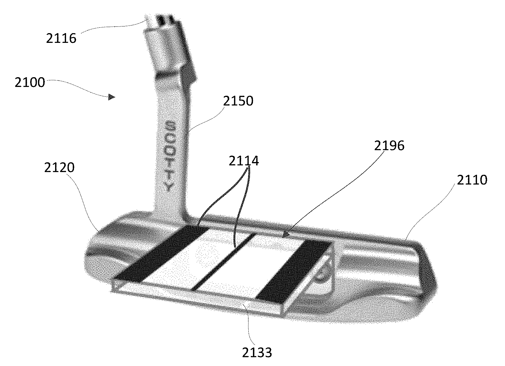
[0144] FIGS. 59-61 illustrate another embodiment of a golf club that can be adapted to have a site alignment member coupled thereto. FIG. 59 is rear perspective view of a putter 2100 with a site alignment member 2196 coupled thereto, and FIG. 60 is an exploded rear perspective view of the putter 2100 and an alignment adapter platform 2117 (also referred to herein as "alignment adapter" or "alignment platform" or "platform"). The putter 2100 is an example of a Scotty Cameron Studio Style putter to which the site alignment member 2196 can be removably coupled using the alignment adapter platform 2117. The putter 2100 includes a head 2120, a face 2110, and a hosel 2150 coupled to a shaft 2116. The site alignment member 2196 and/or the alignment adapter platform 2117 can each be formed with, for example, a light weight molded material, such as for example, plastic, resin, acrylic or any other suitable material. In some embodiments, the site alignment member 1996 and/or the alignment adapter platform 2117 can each be formed with a metal or carbon fiber material as desired.
[0145] As shown in FIG. 60, the site alignment member 2196 can be coupled to a rear cavity of the head 2120 via the alignment platform 2117. In this embodiment, the alignment platform 2117 includes a flange 2133 that can be coupled to a surface extending substantially vertically from a top surface of the putter head 2120 using existing screws 2135 (already provided with the putter 2100). The screws 2135 can be received through holes 2136 defined by the alignment platform 2117. A selected site alignment member 2196 can be removably coupled to the alignment platform 2117 using screws 2118 in a similar manner as described above for putter 1900. For example, the screws 2118 can be received through the bottom side of the alignment platform 2117 through receiving holes 2134 defined by the alignment platform 2117 and into the site alignment member 2196 to secure the site alignment member 2196 to the putter 2100, as shown in FIGS. 59 and 61. As also shown in FIGS. 59 and 61, the site alignment member 2196 includes alignment markings/pattern 2114 on a top surface. A top view of two alternative example site alignment members 2196-1 and 2196-2 that can be coupled to the putter 2100 in the same manner as the site alignment member 2196 using the platform 2117 are also shown in FIG. 61. The site alignment member 2196-1 includes alignment markings 2114-1, and the site alignment member 2196-1 includes alignment markings 2114-2.
[0146] FIGS. 62-64 illustrate another embodiment of a golf club that can be adapted to have a site alignment member coupled thereto. FIG. 62 is rear perspective view of a putter 2200 with a site alignment member 2296 coupled thereto, and FIG. 63 is A BOTTOM perspective view of the putter 2200 and site alignment member 2296. The putter 2200 is an example of a Scotty Cameron Future X5 putter to which the site alignment member 2296 can be removably coupled. The putter 2200 includes a head 2220, a face 2210, and a hosel 2250 coupled to a shaft (not shown). The site alignment member 2296 can be formed with, for example, a light weight molded material, such as for example, plastic, resin, acrylic or any other suitable material. In some embodiments, the site alignment member 1996 can be formed with a metal or carbon fiber material as desired.
[0147] As shown in FIGS. 62 and 63, in this embodiment, the site alignment member 2296 can be disposed within a cavity defined ion a top portion of the head 2220 of the putter 2200 and a bottom attachment plate 2238. As shown in FIG. 63, the attachment plate 2238 can be removably coupled to the head 2220 with existing weight adjustment screws 2237 provided within the putter 2200. The screws 2237 can be received through holes 2239 defined by the attachment plate 2238 of the site alignment member 2296. The site alignment member 2296 also includes markings/pattern 2214 on a top portion of the site alignment member 2296 as shown in FIGS. 62 and 64 in addition to any desired branding on the sole FIG. 63. Also shown in FIG. 64 are two alternative example site alignment members 2296-1 and 2296-2 that can be coupled to the putter 2200 in the same manner as the site alignment member 2296. For example, although not shown in FIG. 64, the site alignment members 2296-1 and 2296-2 can each include an attachment plate 2238 as described for site alignment member 2296. The site alignment member 2296-1 includes alignment markings 2214-1, and the site alignment member 2296-1 includes alignment markings 2214-2.
[0148] FIGS. 65-69 illustrate another embodiment of a golf club that can be adapted to have a site alignment member removably coupled thereto. FIGS. 65A-65B are top views of a putter 3000 with a site alignment member 3004 coupled thereto, and FIG. 66 is rear view of the putter 3000 and site alignment member 3004. The putter 3000 includes a head 3010 defining a top surface 3020, a face 3022, a rear portion 3054, and a hosel 3030 coupled to a shaft (not shown). The site alignment member 3004 can be formed with, for example, a metal or carbon fiber material. In some embodiments, the site alignment member 3004 can be formed with a light weight molded material, such as for example, plastic, resin, acrylic or any other suitable material as desired.
[0149] As shown in FIGS. 67-69, in this embodiment, an attachment plate 3040 of the site alignment member 3004 can be disposed within a slot or nest 3050 defined by a rear portion 3054 of the head 3010 of the putter 3000. As shown, the attachment plate 3040 can be removably coupled to the head 3010 with a screw 3060. The screw 3060 can be received through a hole 3058 within the rear portion 3054 of the head 3010 and a threaded hole 3062 defined by the attachment plate 3040 of the site alignment member 3004. The site alignment member 3004 may also include markings/pattern (not shown) on a top surface 3066 of the site alignment member 3004.
[0150] FIGS. 70-76 illustrate yet another embodiment of a golf club that can be adapted to have a site alignment member removably coupled thereto. FIG. 70 is a rear perspective view of a putter 4000 with a site alignment member 4004 coupled thereto. FIG. 71 is rear end view of the putter 4000 and site alignment member 4004. FIG. 72 is a rear perspective view of the putter 4000 with the site alignment member disassembled therefrom.
[0151] The putter 4000 includes a head 4010, a top surface 4020, a face 4022, and a hosel 4030 coupled to a shaft (not shown). A rear portion 4054 of the putter 4004 includes a pair of curved members 4056 which extend rearward and curve inward toward a rear end of the site alignment member 4004 when the member 4004 is coupled to the putter 4000.
[0152] The site alignment member 4004 can be formed with, for example, a metal or carbon fiber material. In some embodiments, the site alignment member 4004 can be formed with a light weight molded material, such as for example, plastic, resin, acrylic or any other suitable material as desired.
[0153] As shown in FIGS. 72-76, an attachment plate 4040 of the site alignment member 4004 can be disposed within a slot or nest 4050 defined by the rear portion 4054 of the head 4010 of the putter 4000. In the embodiment of FIGS. 72-76, the nest 4050 includes a planar floor 4070, opposing sidewalls 4072 and a rear wall 4074 dimensioned to receive an attachment plate 4040 of the site alignment member 4004. As shown, the attachment plate 4040 can be removably coupled to the head 4010 with a screw 4060. The screw 4060 can be received through a hole 4058 within the rear portion 4054 of the head 4010 and a threaded hole (not shown) defined by the attachment plate 4040 of the site alignment member 4004. The site alignment member 4004 may also include markings/pattern (not shown) on a top surface 4066 of the site alignment member 4004.
[0154] FIGS. 79-81 illustrate yet an additional embodiment of a golf club that can be adapted to have a site alignment member removably coupled thereto. FIG. 79 is a top view of a putter 5000 with a site alignment member 5004 coupled thereto. FIG. 80 is a disassembled bottom perspective view of the putter 5000. FIG. 81 is a disassembled top perspective view of the putter 5000.
[0155] The putter 5000 includes a body 5010, a face 5012, and a hosel 5016 coupled to a shaft 5020. The body 5010 includes a pair of curved members 5024 which extend rearward and curve inward toward a rear end of the site alignment member 5004 when the member 5004 is received by the putter 5000. The body 5010 further includes an alignment guide housing 5070 configured to receive the alignment member 5004.
[0156] The site alignment member 5004 may have a top surface 5005 including one or more alignment markings, a bottom surface 5006 opposite the top surface, and an attachment member 5007 protruding from the bottom surface 5006. As shown, the guide housing 5070 defines a slot 5074 dimensioned to receive the attachment surface 5007 of site alignment member 5004. As shown, the site alignment member 5004 can be removably inserted into the slot 5074 and secured to the guide housing 5070 by a guide screw 5026. The screw 5026 can be received through a hole 5080 within a rear face of the guide housing 5070 and may contact a rear edge of the attachment member 5007 when engaged within the hole 5080. As shown, the alignment guide housing 5070 defines a cutout portion 5071 in an upper surface of the slot 5074. When the attachment member 5007 of the site alignment member 5004 is received within the slot 5074, the top surface 5005 covers the cutout portion 5071.
[0157] The site alignment member 5004 can be formed with, for example, a metal or carbon fiber material. In some embodiments, the site alignment member 5004 can be formed with a light weight molded material, such as for example, plastic, resin, acrylic or any other suitable material as desired. Site alignment members 5004' and 5004'' are substantially similar to site alignment member 5004 but include different alignment markings.
[0158] As shown in FIGS. 80-81, a loft shim 5028 can be disposed between an inner surface of the face 5012 and a front portion of the body 5010. In one embodiment the face 5012 is secured to the body 5010 with a pair of face screws 5032. The body 5010 further defines cavities 5036 for receiving weighting screws 5040.
[0159] Both the offset and the lie angle of the putter 500 may be adjusted to suit the preferences of a user. Specifically, offset of the putter 5000 may be adjusted by arranging the hosel 5016 relative to offset bushings 5050. The hosel 5016 and offset bushings 5050 may circumscribe an offset screw 5054 received by the body 5010. A lie angle of the putter 5000 may be adjusted using a lie angle shim 5060 secured by a lie angle screw 5066.
[0160] FIGS. 82-83 illustrate yet another embodiment of a golf club that can be adapted to have a site alignment member removably coupled thereto. FIG. 82 is a rear perspective view of a putter 6000 with a site alignment member 6004 coupled thereto. As shown, in FIG. 82, the putter 6000 includes a shaft 6006 coupled to a hosel 6030. FIG. 83 is a partially disassembled rear perspective view of putter 600.
[0161] The putter 6000 includes a head 6010, a top surface 6020, and a face 6022 opposite a rear portion 6054. The rear portion 6054 of the putter 6004 includes an arc portion 6056 which extend rearwards from the head 6010 and curves inward toward a rear end of the site alignment member 6004 when the member 6004 is coupled to the putter 6000.
[0162] The site alignment member 6004 can be formed with, for example, a metal or carbon fiber material. In some embodiments, the site alignment member 6004 can be formed with a light weight molded material, such as for example, plastic, resin, acrylic or any other suitable material as desired. As shown in FIG. 82, the site alignment member 6004 may include markings/patterns on a top surface 6009 thereof.
[0163] As shown in FIG. 83, the body 6010 includes an alignment guide housing 6060 configured to receive an attachment member (not shown) defined on a bottom surface of the site alignment member 6004. Specifically, the guide housing 6060 defines a slot 6064 dimensioned to receive the attachment plate of site alignment member 6004. As shown, the site alignment member 6004 can be removably inserted into the slot 6064 and secured by a screw 6070. The screw 6070 can be received through a hole 6074 within a rear face of the guide housing 6060 and may contact a rear edge of the attachment plate of the site alignment member 6004 when engaged within the hole 6074. As shown, the alignment guide housing 6060 defines a cutout portion 6062 in an upper surface of the slot 6064. When the attachment member of the site alignment member 6004 is received within the slot 6064, the top surface 6009 covers the cutout portion 6062.
[0164] An overall weight or weight balance of the putter 6000 may be adjusted by inserting one or both of a pair of weighting screws 6080 into a bottom surface of the head 6010.
[0165] Although not specifically described for each embodiment, it should be understood that any of the various embodiments of a site alignment member (e.g., 1696, 1796, 1896, etc.) can be formed as described, for example, for site alignment member 1696. Further, the various markings/patterns are examples of possible markings/patterns that can be included on a site alignment member and other markings/patterns not specifically shown can alternatively be included. Similarly, the various sizes and shapes of the site alignment members can vary. Moreover, in other embodiments the site alignment members may be coupled to the hosel or shaft of a golf club head or putter head.
[0166] In some embodiments, a golf club kit can be provided that can include a golf club and multiple selectable hosel shims (or lie angle shims) and/or one or more loft angle shims as described herein. For example, multiple hosel shims can be provided with each being configured to provide the golf club with a select lie angle. Multiple loft angle shims can also be included with each providing the golf club with a different loft angle. Thus, a golf club kit can also optionally provided one or more tools that can be used to removably couple or decouple a hosel shim and or a loft angle shim to the golf club such that a user can adjust or change various parameters of the golf club as desired. A golf club kit can also include instructions for coupling and removing a lie angle shim or a loft angle shim as described herein.
[0167] While various embodiments have been described above, it should be understood that they have been presented by way of example only, and not limitation. For example, although some embodiments describe a putter, in other embodiments any golf club can include features and functions described herein. Furthermore, although various embodiments have been described as having particular features and/or combinations of components, other embodiments are possible having a combination of any features and/or components from any of embodiments where appropriate as well as additional features and/or components. For example, although some embodiments describe a putter with an adjustable lie angle and other embodiments describe a putter with an adjustable loft angle, a putter can incorporate both an adjustable lie angle and an adjustable loft angle
* * * * *
D00000
D00001
D00002
D00003
D00004
D00005
D00006
D00007
D00008
D00009
D00010
D00011
D00012

D00013

D00014

D00015

D00016

D00017

D00018

D00019

D00020

D00021
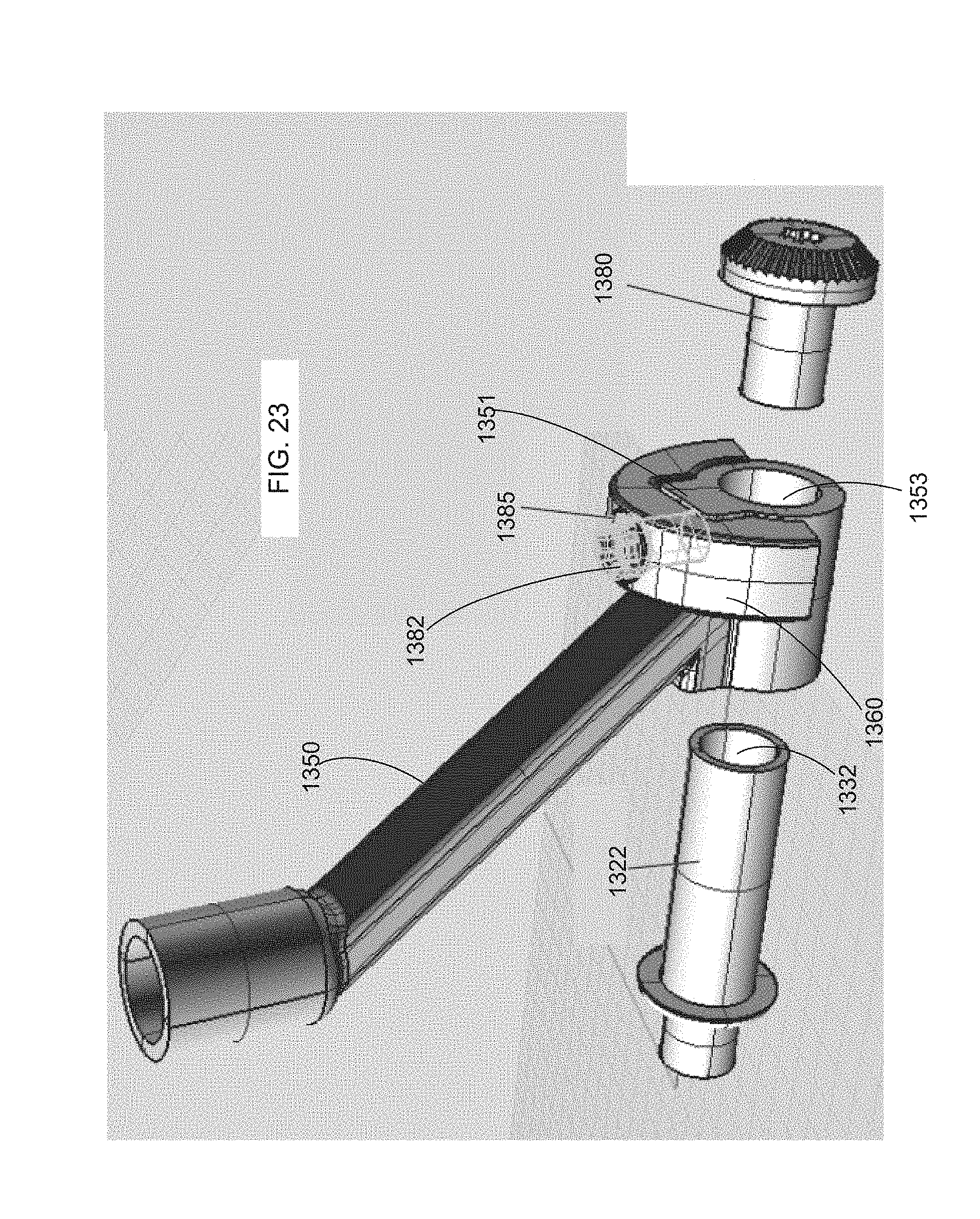
D00022

D00023
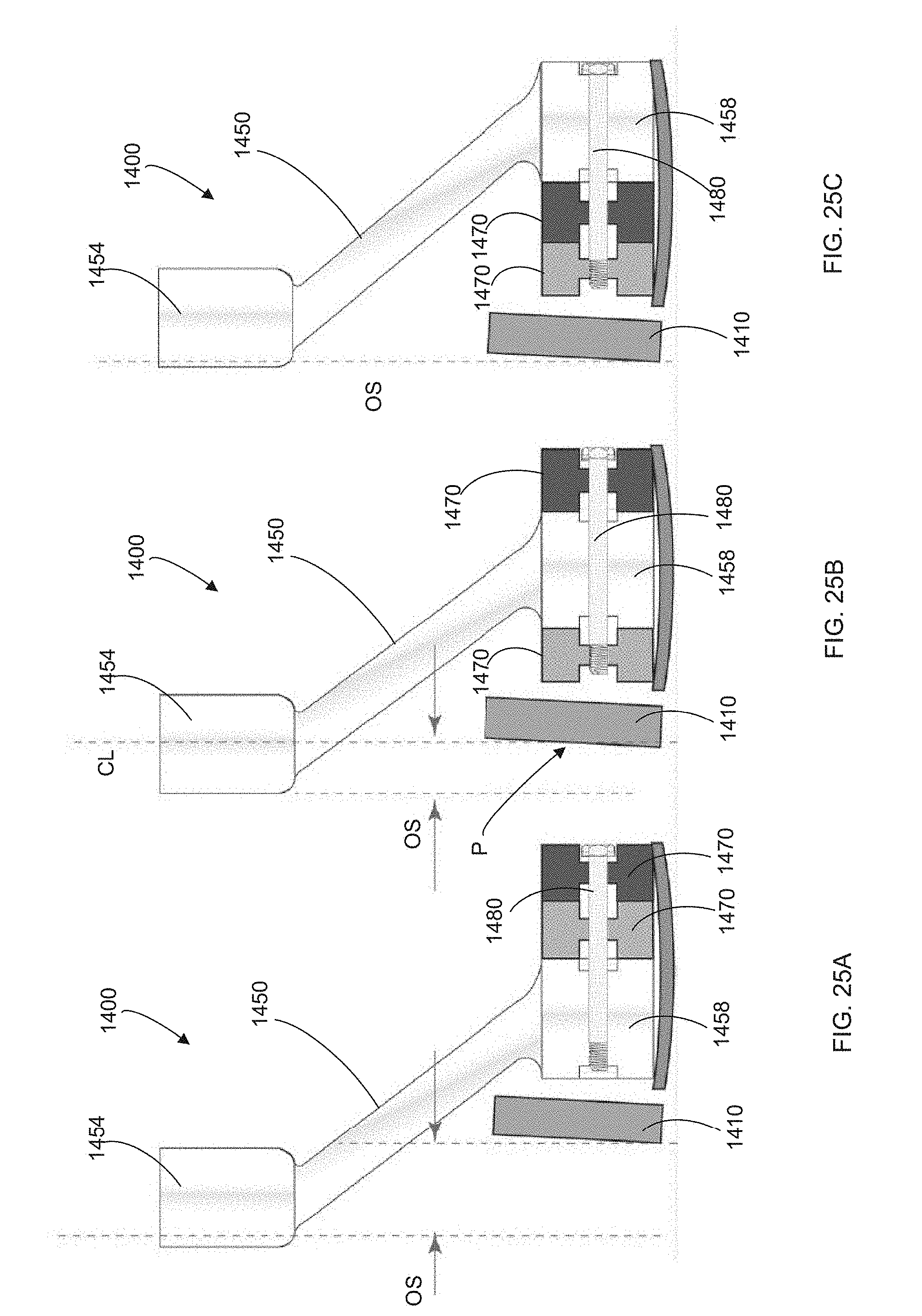
D00024

D00025

D00026

D00027

D00028

D00029

D00030

D00031
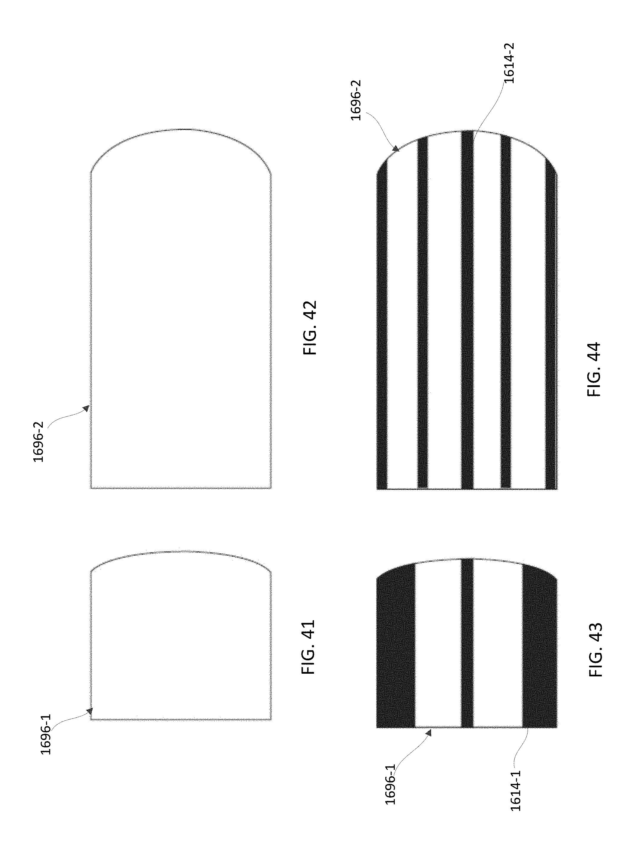
D00032

D00033

D00034

D00035

D00036
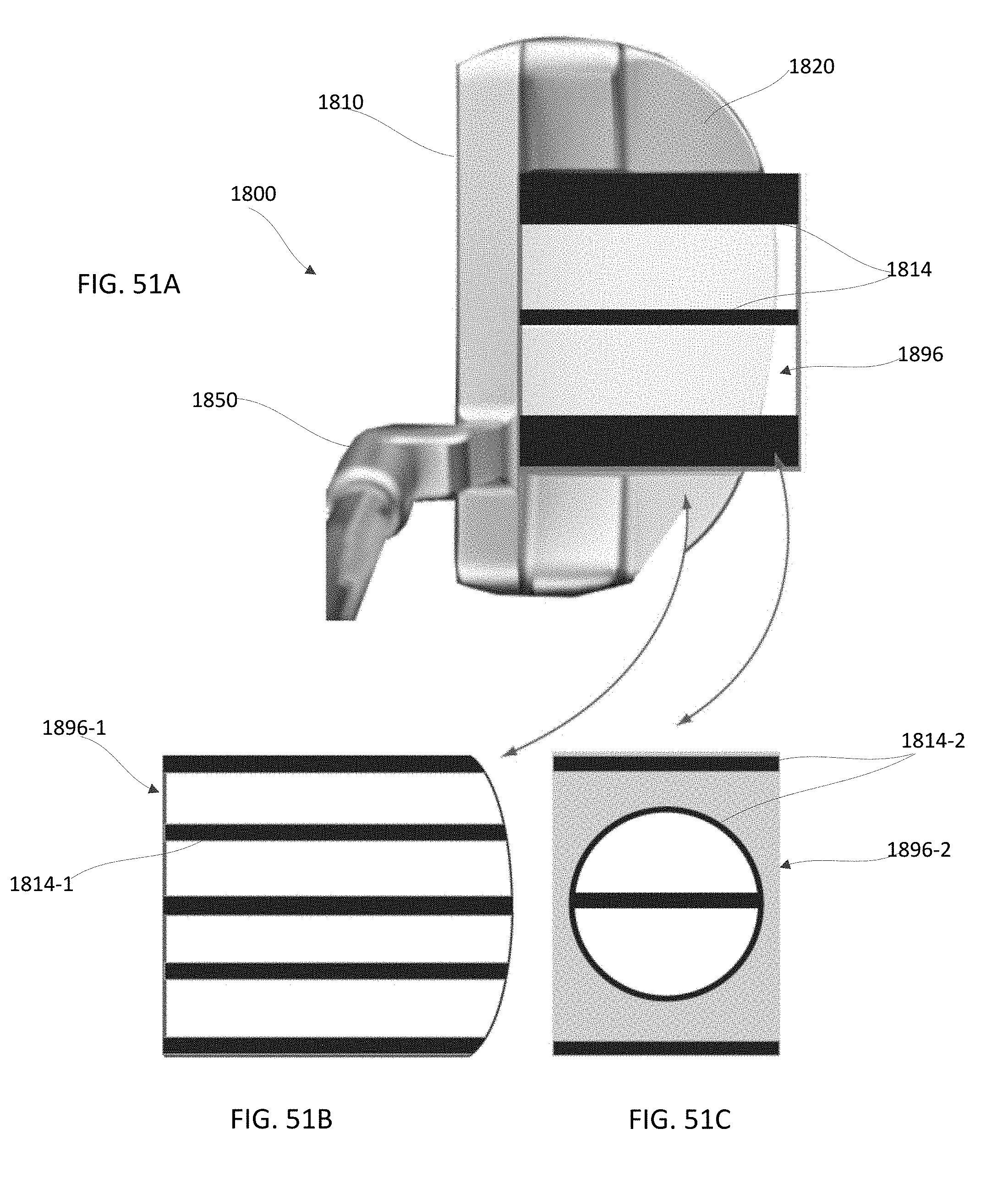
D00037
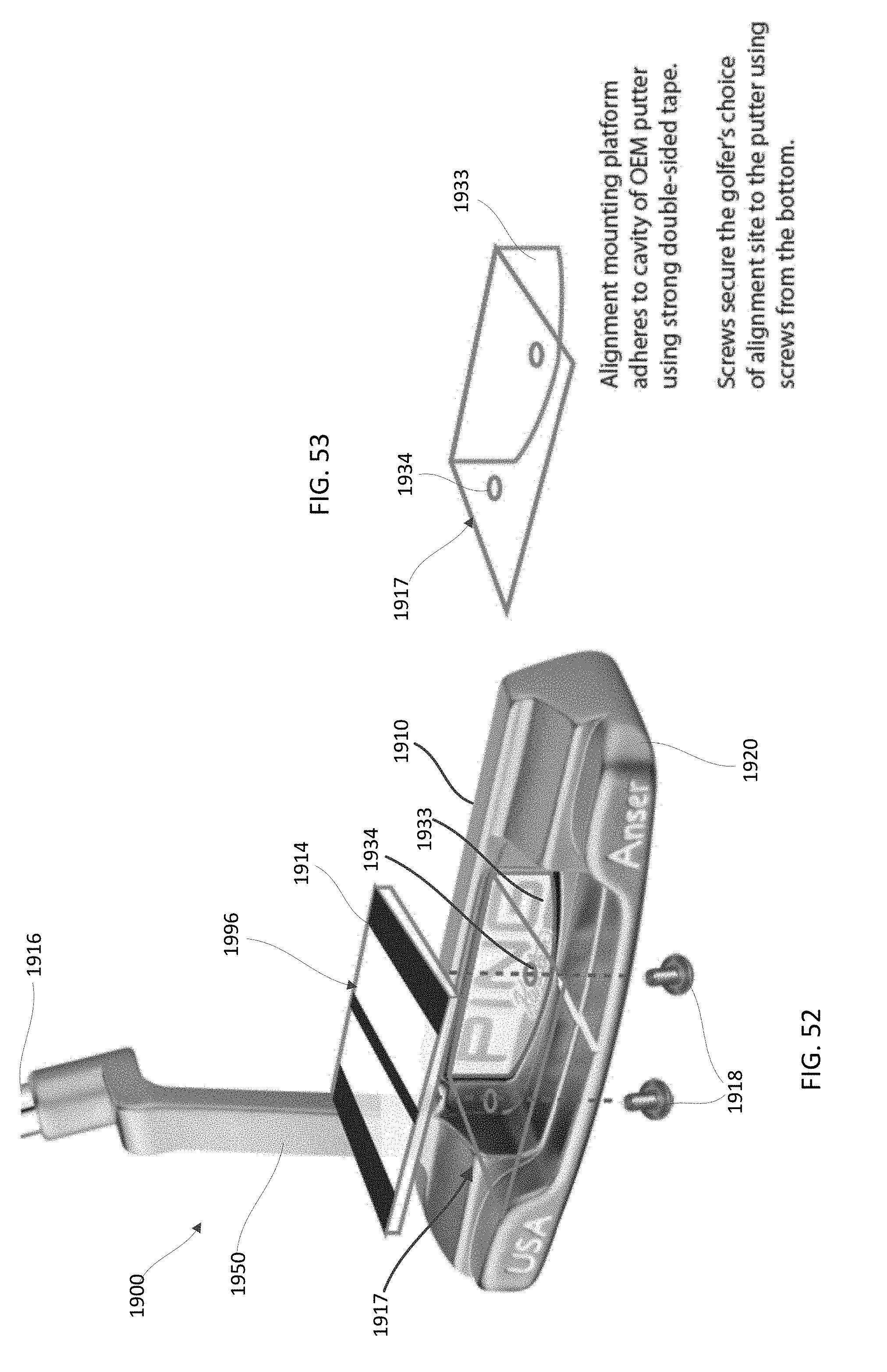
D00038
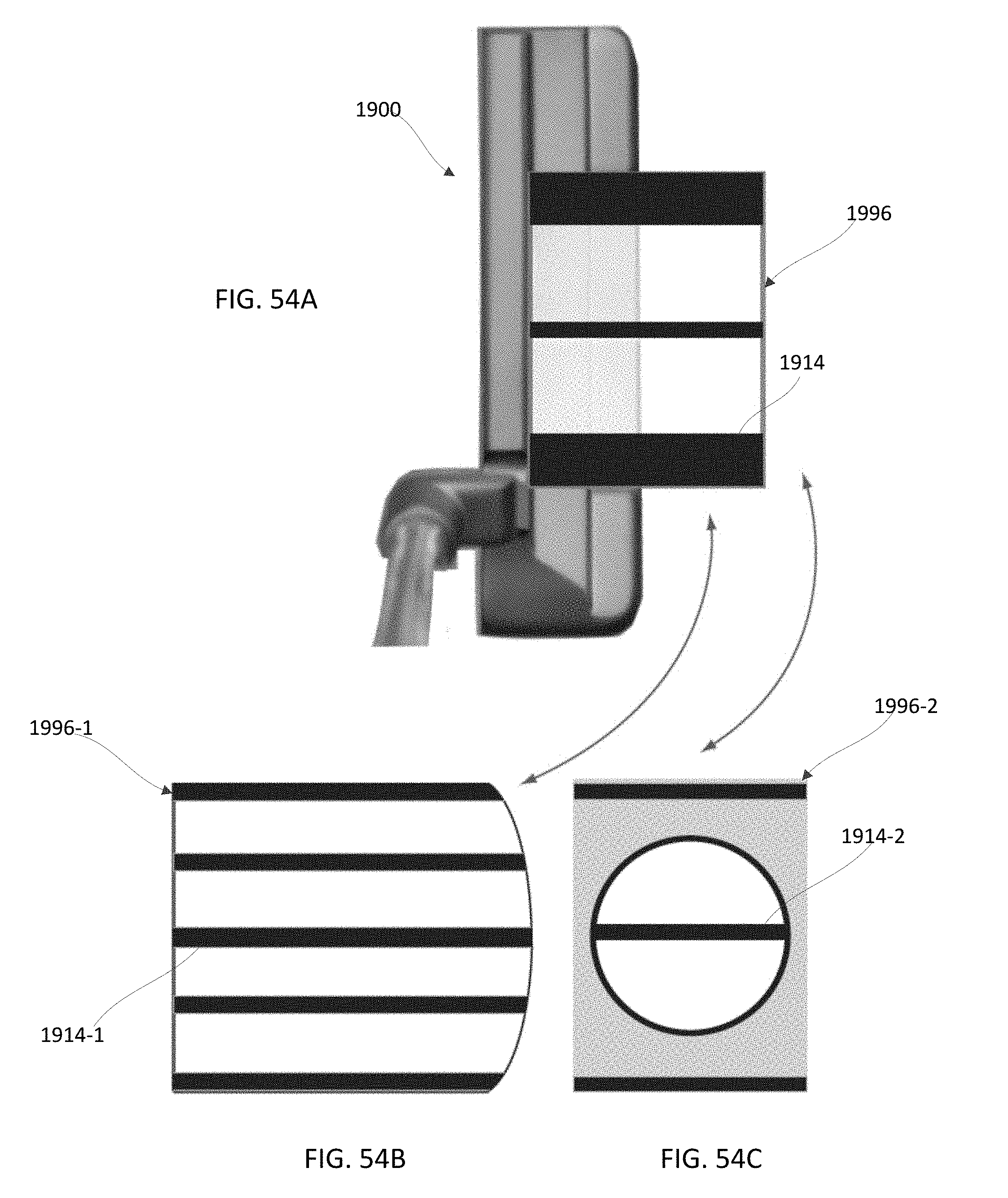
D00039
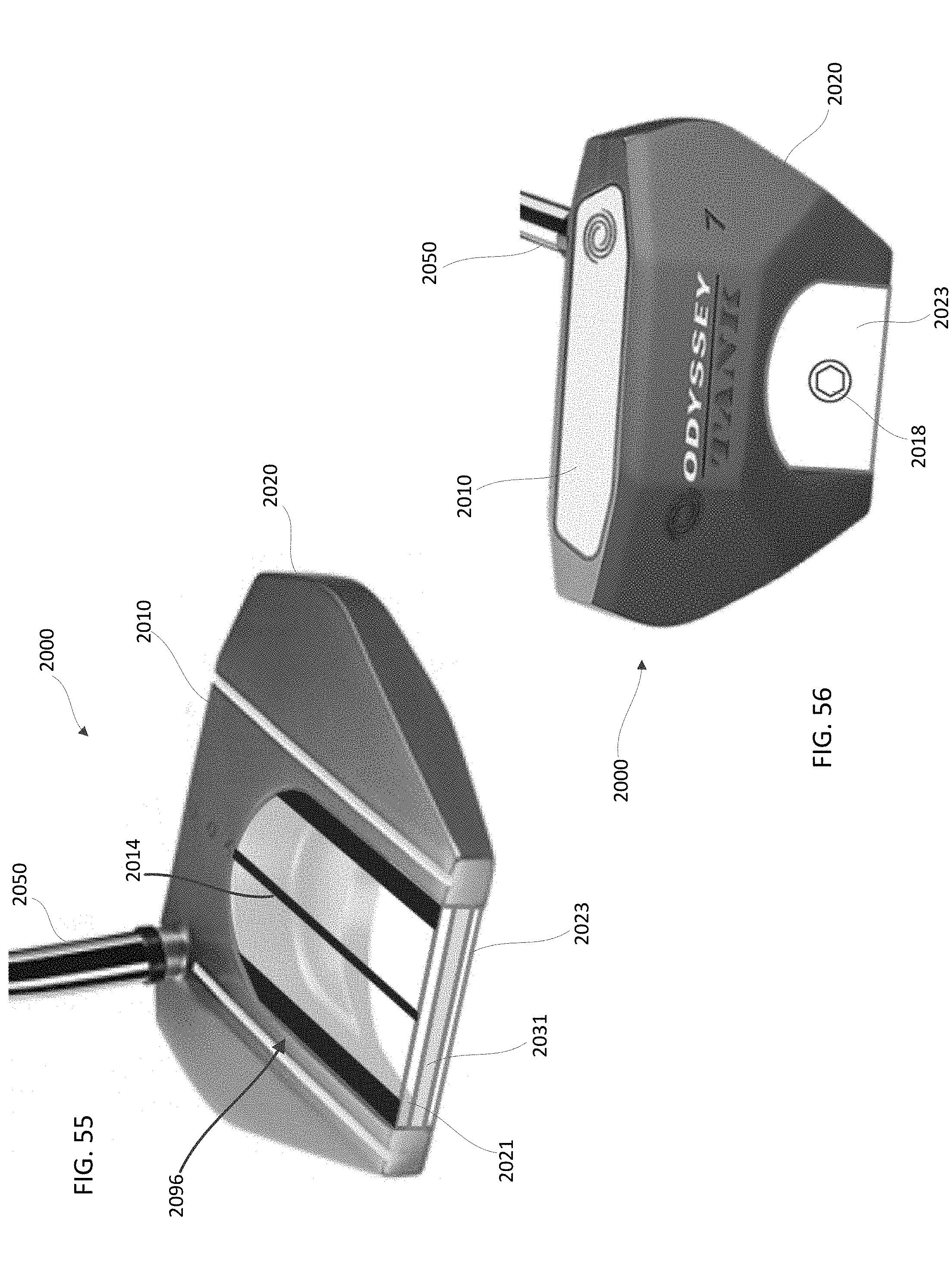
D00040

D00041

D00042

D00043

D00044

D00045
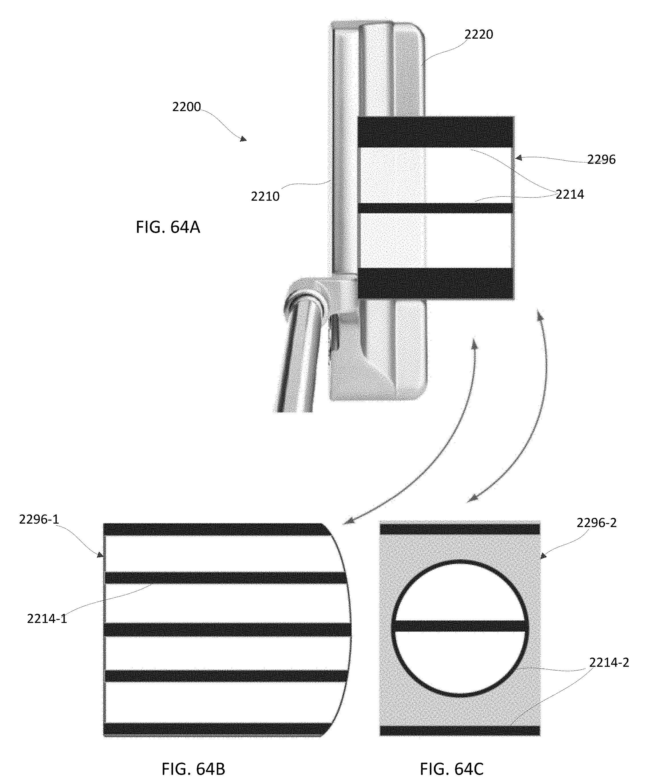
D00046
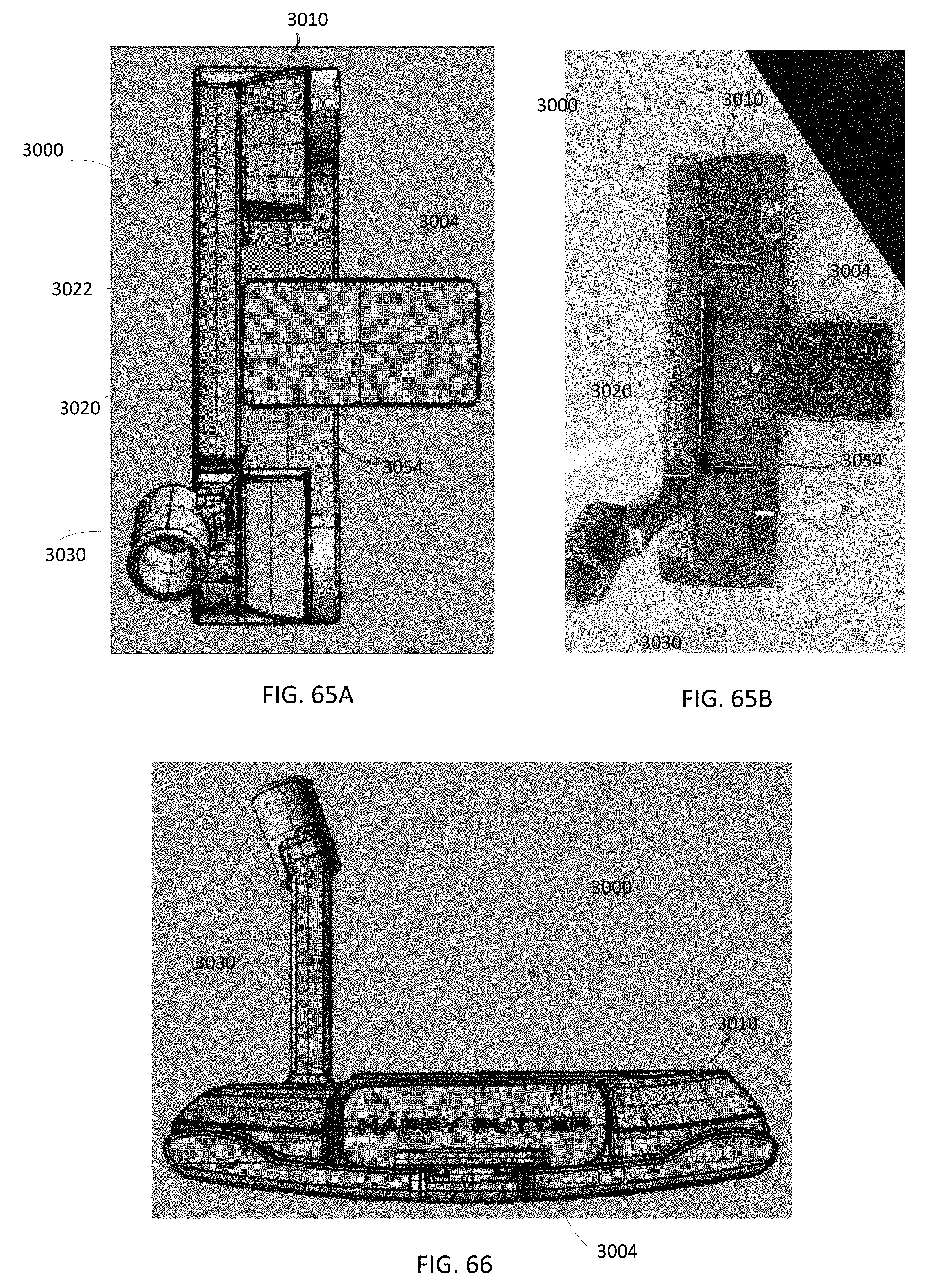
D00047
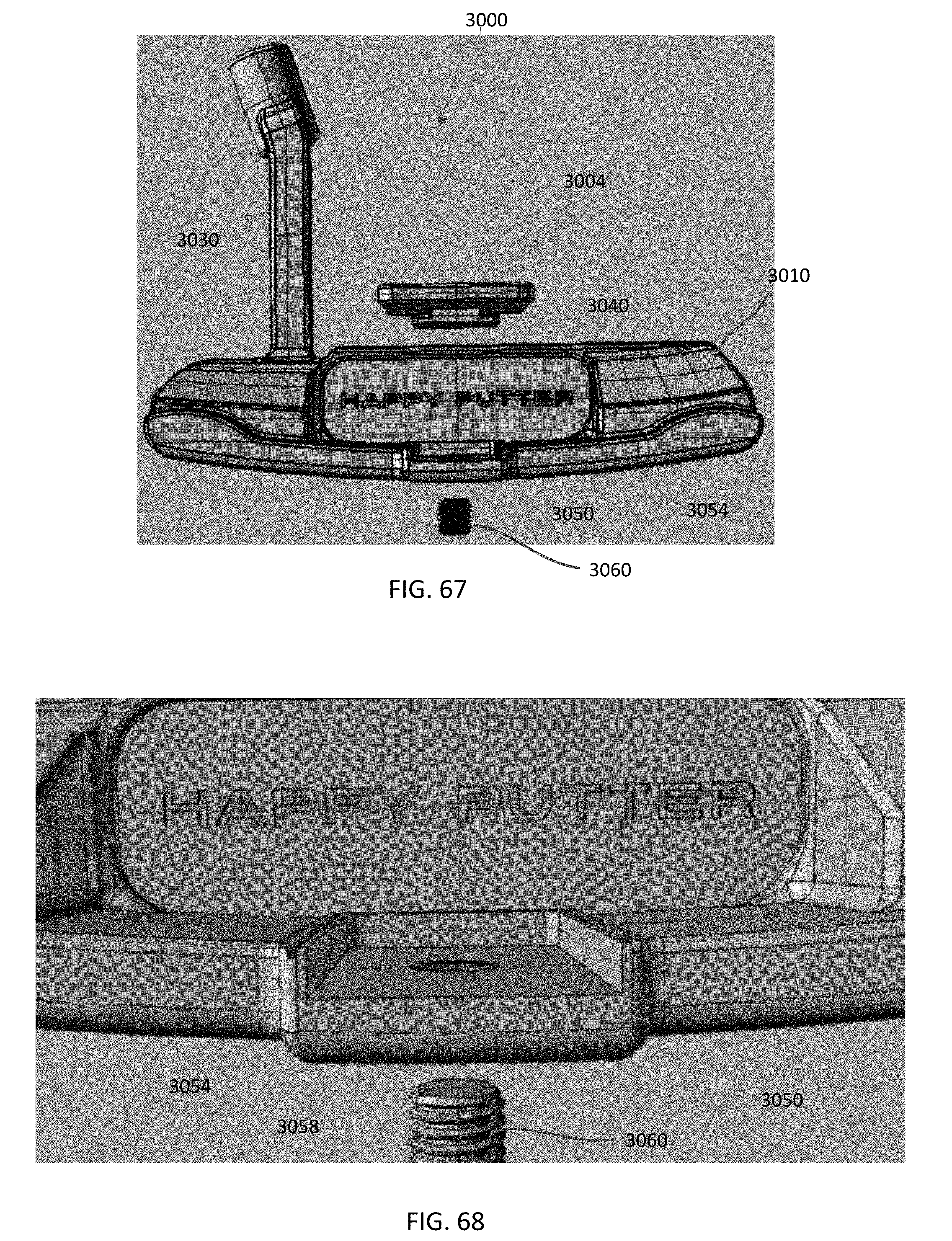
D00048

D00049

D00050

D00051

D00052

D00053

D00054

D00055

D00056
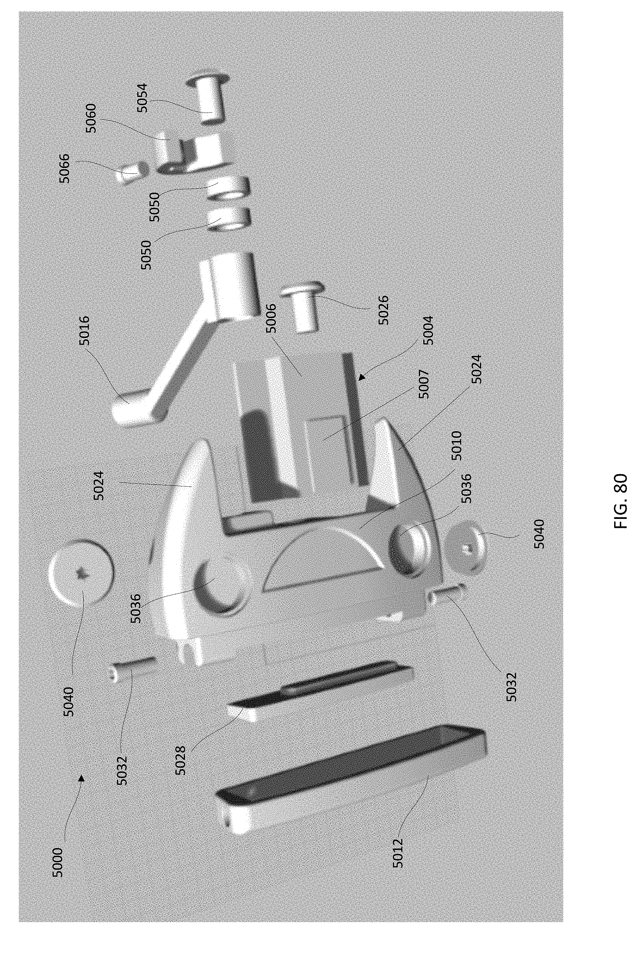
D00057

D00058

D00059
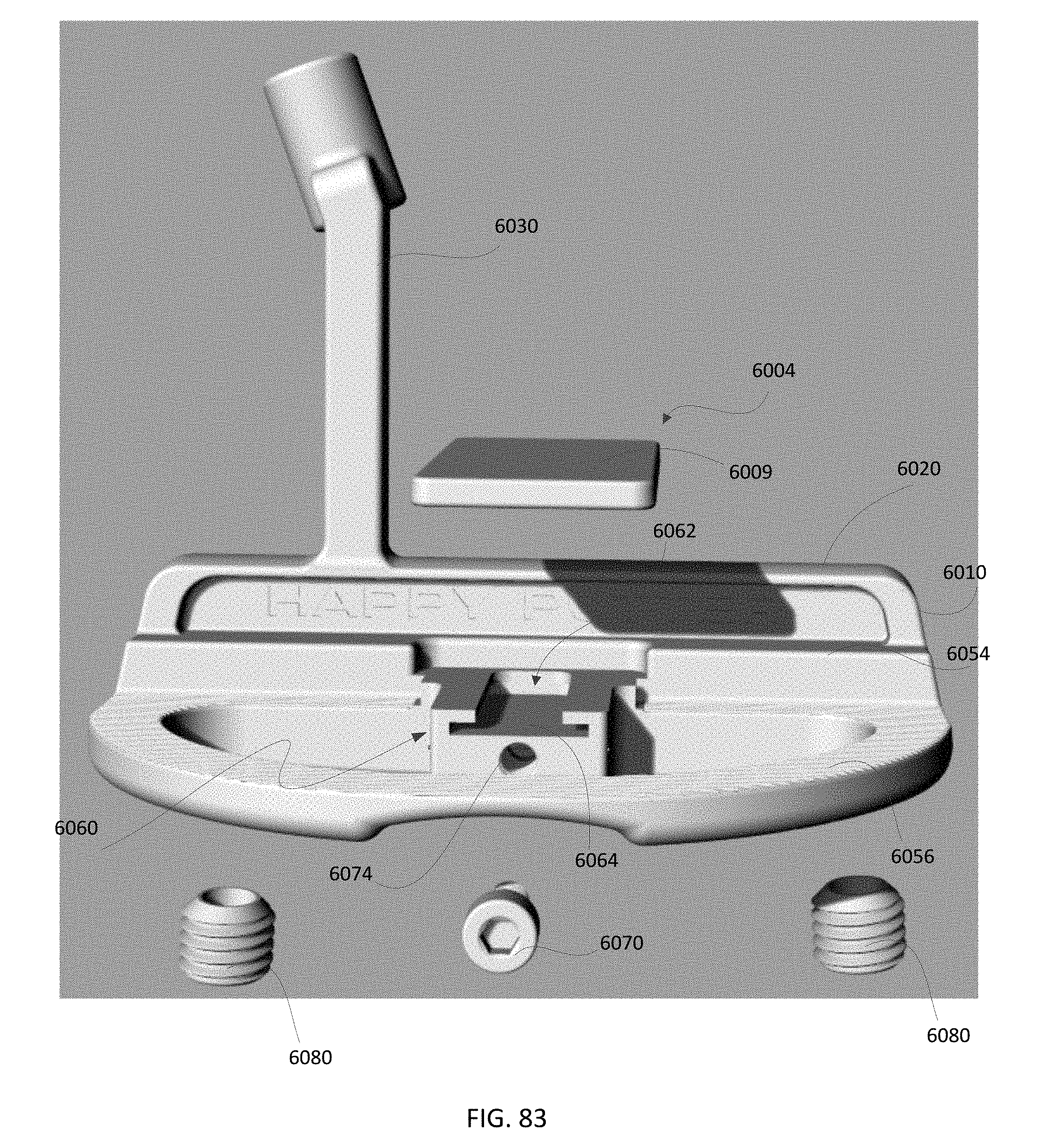
XML
uspto.report is an independent third-party trademark research tool that is not affiliated, endorsed, or sponsored by the United States Patent and Trademark Office (USPTO) or any other governmental organization. The information provided by uspto.report is based on publicly available data at the time of writing and is intended for informational purposes only.
While we strive to provide accurate and up-to-date information, we do not guarantee the accuracy, completeness, reliability, or suitability of the information displayed on this site. The use of this site is at your own risk. Any reliance you place on such information is therefore strictly at your own risk.
All official trademark data, including owner information, should be verified by visiting the official USPTO website at www.uspto.gov. This site is not intended to replace professional legal advice and should not be used as a substitute for consulting with a legal professional who is knowledgeable about trademark law.