Device And Method for Non-Invasive Neuromodulation
Deisseroth; Karl ; et al.
U.S. patent application number 16/037974 was filed with the patent office on 2019-01-24 for device and method for non-invasive neuromodulation. The applicant listed for this patent is The Board of Trustees of the Leland Stanford Junior University. Invention is credited to Karl Deisseroth, M. Bret Schneider.
| Application Number | 20190022425 16/037974 |
| Document ID | / |
| Family ID | 40583766 |
| Filed Date | 2019-01-24 |

| United States Patent Application | 20190022425 |
| Kind Code | A1 |
| Deisseroth; Karl ; et al. | January 24, 2019 |
Device And Method for Non-Invasive Neuromodulation
Abstract
One embodiment involves modifying neural transmission patterns between neural structures and/or neural regions in a noninvasive manner. In a related exemplary method, sound waves are directed toward a first targeted neural structure and characteristics of the sound waves are controlled at the first target neural structure with respect to characteristics of sound waves at the second target neural structure. In response, neural transmission patterns modified to produce the intended effect (e.g., long-term potentiation and long-term depression of the neural transmission patterns). In a related embodiment, a transducer produces the sound for stimulating the first neural structure and the second neural structure, and an electronically-based control circuit is used to control characteristics of the sound waves as described above to modify the neural transmission patterns between the first and second neural structures.
| Inventors: | Deisseroth; Karl; (Stanford, CA) ; Schneider; M. Bret; (Portola Valley, CA) | ||||||||||
| Applicant: |
|
||||||||||
|---|---|---|---|---|---|---|---|---|---|---|---|
| Family ID: | 40583766 | ||||||||||
| Appl. No.: | 16/037974 | ||||||||||
| Filed: | July 17, 2018 |
Related U.S. Patent Documents
| Application Number | Filing Date | Patent Number | ||
|---|---|---|---|---|
| 12263026 | Oct 31, 2008 | 10035027 | ||
| 16037974 | ||||
| 60984225 | Oct 31, 2007 | |||
| Current U.S. Class: | 1/1 |
| Current CPC Class: | A61N 7/00 20130101; A61N 2007/027 20130101; A61N 2007/0078 20130101; A61N 2007/0026 20130101; A61N 2007/0095 20130101 |
| International Class: | A61N 7/00 20060101 A61N007/00 |
Claims
1. A system for modifying neural transmission patterns between a first neural structure and a second neural structure, the system comprising: a transducer arrangement configured and arranged to produce sound for stimulating the first neural structure and the second neural structure; a control circuit configured and arranged to control of characteristics of sound waves at the first target neural structure with respect to characteristics of sound waves at the second target neural structure for modifying the neural transmission patterns between a first neural structure and a second neural structure; and implanted piezoelectric antennas configured to produce an electrical current in response to the sound waves.
2. The system of claim 1, wherein modifying the neural transmission patterns includes one of long-term potentiation and long-term depression of the neural transmission patterns.
3. The system of claim 1, wherein the sound waves at first target neural structure sufficiently raise the temperature of the first target neural structure so as to affect the firing rate of neurons in the first target neural structure.
4. The system of claim 1, wherein the transducer arrangement includes a plurality of transducers that are each configured and arranged to be controlled by the control circuit.
5. A method for modifying neural transmission patterns between a first neural structure and a second neural structure, the method comprising: producing sound waves; directing the sound waves to implanted piezoelectric antennas configured to produce an electrical current in response to the sound waves at a first target neural structure and a second target neural structure; and controlling characteristics of sound waves at the first target neural structure with respect to characteristics of sound waves at the second target neural structure to modify neural transmission patterns.
6. A device for neuromodulation comprising: one or more energy emitters configured and arranged to emit energy that is focused to a focal point; a targeting controller configured and arranged to determine a location in space at which the focal point is desired; and an aiming controller configured and arranged to direct the focal point toward the location in space to non-destructively alter a pattern of functional responsiveness of cells at the location in space for a first time period to change responsiveness between two groups of cells for a second period of time that is substantially greater than the first period of time.
7. The device of claim 6, further including a secondary group of one or more energy emitters, wherein each of the two groups of cells is stimulated by one of the energy emitters.
8. The device of claim 6, wherein the responsiveness between two groups of cells includes neural connectivity.
9. The device of claim 6, wherein the responsiveness between two groups of cells is moderated by long-term potentiation (LTP).
10. The device of claim 6, wherein the responsiveness between two groups of cells is moderated by long-term depression (LTD).
11. The device of claim 6, wherein the energy heats a first group of cells of the two groups of cells thereby changing a spontaneous firing rate of the first group of cells.
12. The device of claim 6, wherein the altering of a pattern of functional responsiveness is due to mechanical perturbations of a cell from the energy.
13. The device of claim 6, wherein the energy is focused using one of a lens and a curved transducer portion.
14. The device of claim 6, wherein the energy is focused by aiming an array of the energy emitters at the focal point.
15. A system for modifying neural transmission patterns between a first neural structure and a second neural structure, the system comprising: a transducer arrangement configured and arranged to wirelessly stimulate the first neural structure and the second neural structure; a control circuit configured and arranged to control of characteristics of the stimulus at the first target neural structure with respect to characteristics of sound waves at the second target neural structure thereby modifying the neural transmission patterns between a first neural structure and a second neural structure; and an implanted piezoelectric antenna configured to produce an electrical current in response to the sound waves.
16. The system of claim 15 wherein the transducer arrangement produces ultrasound for stimulating the first neural structure and the second neural structure.
17. The system of claim 15 wherein the transducer arrangement produces radio frequency energy for stimulating the first neural structure and the second neural structure.
18. The system of claim 15 wherein the transducer arrangement produces a magnetic field for stimulating the first neural structure and the second neural structure.
19. The system of claim 15 wherein the transducer arrangement produces ionizing radiation for stimulating the first neural structure and the second neural structure.
Description
RELATED PATENT DOCUMENTS
[0001] This is a conversion of U.S. Provisional Patent Application Ser. No. 60/984,225, entitled "Device and Method for Non-Invasive Neuromodulation," and filed on Oct. 31, 2007, to which benefit is claimed under 35 U.S.C. .sctn. 119.
FIELD OF THE INVENTION
[0002] The present invention relates generally to systems and approaches for stimulation of neural circuits and more particularly to facilitating long-term potentiation or long-term depression between neural circuits.
BACKGROUND
[0003] Long-term potentiation (LTP) involves the process of establishing an association between the firing of two cells or groups of cells. For instance, Hebb's rule essentially states that if an axon of cell A is near enough to excite a cell B and repeatedly or persistently takes part in firing cell B, an increase in the strength of the chemical synapse between the cells takes place such that A's efficiency, as one of the cells firing B, is increased. LTP has been shown to last from minutes to several months. Conditions for establishing LTP are favorable when a pre-synaptic neuron and a post-synaptic neuron are both depolarized in a synchronous manner. An opposite effect, long-term depression (LTD), has also been established. LTD is the weakening of a neuronal synapse that lasts from hours to months. In the cerebellar Purkinje cells, LTD results from strong synaptic stimulation. By contrast, in the hippocampus, LTD results from persistent weak synaptic stimulation, or when a pre-synaptic neuron and a postsynaptic neuron discharge in an asynchronous manner. Since the establishment of Hebb's original rule, additional "Hebb's Rules" have been proposed for the prediction of self-organization of neuronal systems, and these rules appear to govern the process by which the brain is effectively sculpted over time in order to master the demands of the environment.
[0004] Neurons and other electrically excitable cells (including cardiac cells and some endocrine cells) have spontaneous firing rates: they discharge action potentials at a baseline rate, in the absence of external stimulation or suppression. This spontaneous firing rate is affected by temperature. Generally, the warmer an electrically excitable cell, the faster the spontaneous firing rate, and the colder the cell, the slower the firing rate. When cells become extremely warm, such as in a very high fever, they have a high propensity to fire. At extremes, such an increase in firing rates may manifest as a risk of a febrile seizure.
[0005] Neuromodulation is the control of nerve activity, and is usually implemented for the purpose of treating disease. In the strictest sense, neuromodulation may be accomplished with a surgical intervention like cutting an aberrant nerve tract. However, the semi-permanent nature of a surgical procedure leaves little room for later adjustment and optimization. Likewise, it could be asserted that neuromodulation can be accomplished with chemical agents or medications. Chemical agents or medications may be undesirable because, for example, many medications are difficult to deliver to specific anatomy, and because the titration (increasing or decreasing the dose of a medication) is a slow and imprecise way to achieve a desired effect on a specific target. Consequently, the term neuromodulation usually implies the use of energy-delivering devices.
[0006] Several categories of device-based neuromodulation methods are known in the art. These include electrical neuromodulation, magnetic neuromodulation and opto-genetic neuromodulation.
[0007] Electrical nerve stimulation is well-established. Examples of electrical approaches include transcutaneous electrical nerve stimulation (TENS) units, and the surgically implanted electrodes of deep brain stimulation (DBS). TENS units are used to lessen superficial nerve pain within skin and muscle. Because the device is non-invasive and has a low power output, its use involves little risk. However, the efficacy of TENS is limited to nerve distributions very close to the surface. Additionally, TENS has little focusing ability for targeting with close tolerances. Moreover, its therapeutic use shows a fairly small effective treatment area. DBS is a useful approach for treating conditions including Parkinson's disease, essential tremor, epilepsy, chronic pain, depression and obsessive-compulsive disorder. In the case of Parkinson's disease, a multi-contact electrode may be neurosurgically implanted in the subthalamic nucleus of a patient. Once connected to a pulse generation unit similar to a cardiac pacemaker device, the electrodes may be electrically pulsed at various rates, effectively driving the activity of the neurons immediately adjacent to the electrode contacts, using currents of about 3 amps and voltages between 1 and 10. Subsequently, various configurations of electrode pairs or monopolar configurations may be empirically tested on the patient for effect and tolerability. At a later time, the circuit configuration or pulse parameters may be changed by the physician in charge, usually without the need to physically disturb the implanted electrode. One disadvantage of DBS is that, by definition, it requires a highly invasive and risky neurosurgical implantation procedure. If the site of implantation is later deemed suboptimal, or if the device physically fails, more surgery is required.
[0008] Magnetic stimulation involves the discharge of large capacitors into an electrically conductive coil placed external to a patient's brain or body. As electrical current runs through the coil, a magnetic field is induced, which in turn, induces an electric field in nerve membranes and surrounding fluid. This forces nerves to depolarize with each discharge of the capacitors in the machine. Magnetic stimulation, when delivered at rates of 5-20 Hz, tend to be stimulating to nerves that it affects, for some time after the magnetic pulse delivery has stopped. Pulse rates of less than 1 Hz tend to suppress the activity of affected nerves after stimulation has ended. Very fast pulse trains (e.g., 50 Hz), punctuated by absence of pulses 6-9 times per second ("theta rhythm") also tend to suppress the activity of affected neurons. Magnetic neuromodulation, in the form of repetitive transcranial magnetic stimulation, is useful for the treatment of depression, and likely several other neurological and psychiatric conditions. The derived effects may last from minutes to months after the end of magnetic treatment. One limitation of magnetic neuromodulation is the difficulty in achieving tight focus of the effect, since magnetic fields capable of penetrating to useful depth tend to be large in footprint, as dictated by the Biot-Savart Law.
[0009] Opto-genetic neuromodulation is a newly discovered approach which has the advantages of being neuron-type specific. Using this approach, light-sensitive ion channels or pumps are genetically transferred to the targeted neurons of the brain to be stimulated. A flashing light from an implanted device provides a signal to these channels or pumps to activate. This leads to either neuronal depolarization, or neuronal hyperpolarization, depending upon the nature of the light-sensitive channel or pump. Opto-genetic approaches lend themselves to both neuronal up-regulation and down-regulation. Disadvantages include the requirement of implanted hardware, and the need for the genetic modification of targeted neurons.
[0010] Ultrasound is mechanical vibration at frequencies above the range of human hearing, or above 16 kHz. Most medical uses for ultrasound use frequencies in the range of 1 to 20 MHz. Low to medium intensity ultrasound products are widely used by physicians, nurses, physical therapists, masseurs and athletic trainers. The most common applications are probably wanning stiff, swollen or painful joints or muscles in a manner similar to a hot compress, but with better penetration. Many ultrasound products have been commercially available for years, including consumer-grade massage machines. By design, the power on these devices is designed to be too low to warm or otherwise affect structures more than two centimeters or so below the surface. Also, these devices are not capable of tight focus at depth, nor are there means for accurately aiming such devices toward precise structural coordinates within the body. As ultrasound of sufficient strength can cause pain in peripheral nerves with each pulse, it is likely that mechanical perturbations caused by ultrasound can cause nerves to discharge.
SUMMARY OF THE INVENTION
[0011] Various aspects of the present invention are directed to addressing the above issues and/or generally advancing technology in the above-discussed contexts and other contexts.
[0012] In accordance with one embodiment, the present invention is directed to methods, devices and systems that are used to modify neural transmission patterns between neural structures and/or regions. Consistent herewith, one exemplary method involves directing sound waves toward a first targeted neural structure, controlling characteristics of the sound waves at the first target neural structure with respect to characteristics of sound waves at the second target neural structure, and in response, modifying neural transmission patterns. In a related embodiment, a transducer produces the sound for stimulating the first neural structure and the second neural structure, and an electronically-based control circuit is used to control characteristics of the sound waves as described above to modify the neural transmission patterns between the first and second neural structures.
[0013] In accordance with one embodiment, the present invention is directed to methods, devices and systems that are used to modify neural transmission patterns between neural structures and/or regions. Consistent herewith, one exemplary method involves directing stimuli toward a first targeted neural structure, controlling characteristics of the stimulus at the first target neural structure with respect to characteristics of stimulus at the second target neural structure, and in response, modifying neural transmission patterns. In a related embodiment, a transducer produces the stimulus for the first neural structure and the second neural structure, and an electronically-based control circuit is used to control characteristics of the stimulus as described above to modify the neural transmission patterns between the first and second neural structures.
[0014] As discussed with the detailed description that follows, more specific embodiments of the present invention concern various levels of detail for controlling the neural-transmission modulation.
[0015] The above summary of the present invention is not intended to describe each illustrated embodiment or every implementation of the present invention. The figures in the detailed description that follow more particularly exemplify these embodiments.
BRIEF DESCRIPTION OF THE DRAWINGS
[0016] The invention may be more completely understood in consideration of the detailed description of various embodiments of the invention that follows in connection with the accompanying drawings, in which:
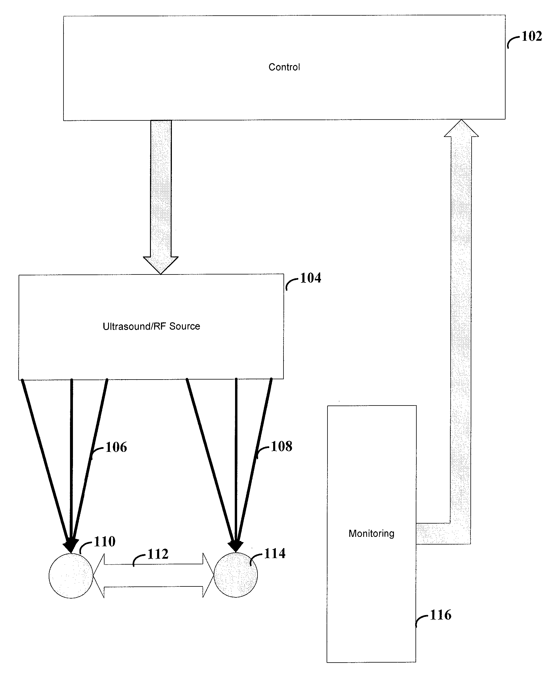
[0017] FIG. 1 shows a system for altering neural patterns between two groups of cells, according to an example embodiment of the present invention;
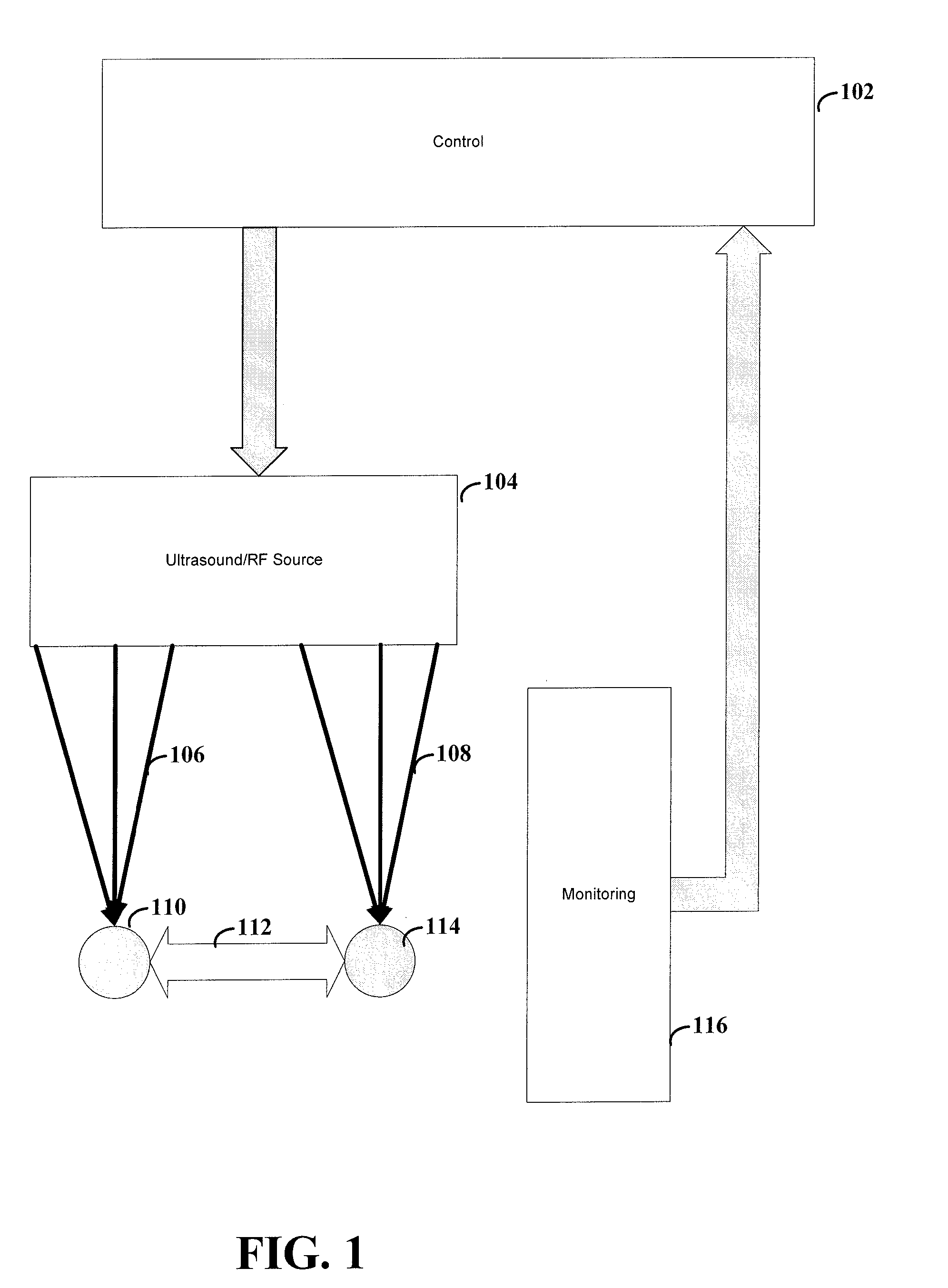
[0018] FIG. 2A shows the use of two focused-beam ultrasound transducers physiologically suppressing the connection between two regions, according to an example embodiment of the present invention;
[0019] FIG. 2B shows the use of an electronically focused ultrasound transducer array to physiologically augment the connection between two regions, according to an example embodiment of the present invention;
[0020] FIG. 3A shows a specific application of the present invention in which LTP is facilitated within the "trisynaptic circuit" of the human hippocampus, according to an example embodiment of the present invention;
[0021] FIG. 3B shows the use of the present invention, to produce LTP between the entorhinal cortex and the CA3 fields of a human hippocampus, as can be used to augment the encoding of memory, according to an example embodiment of the present invention;
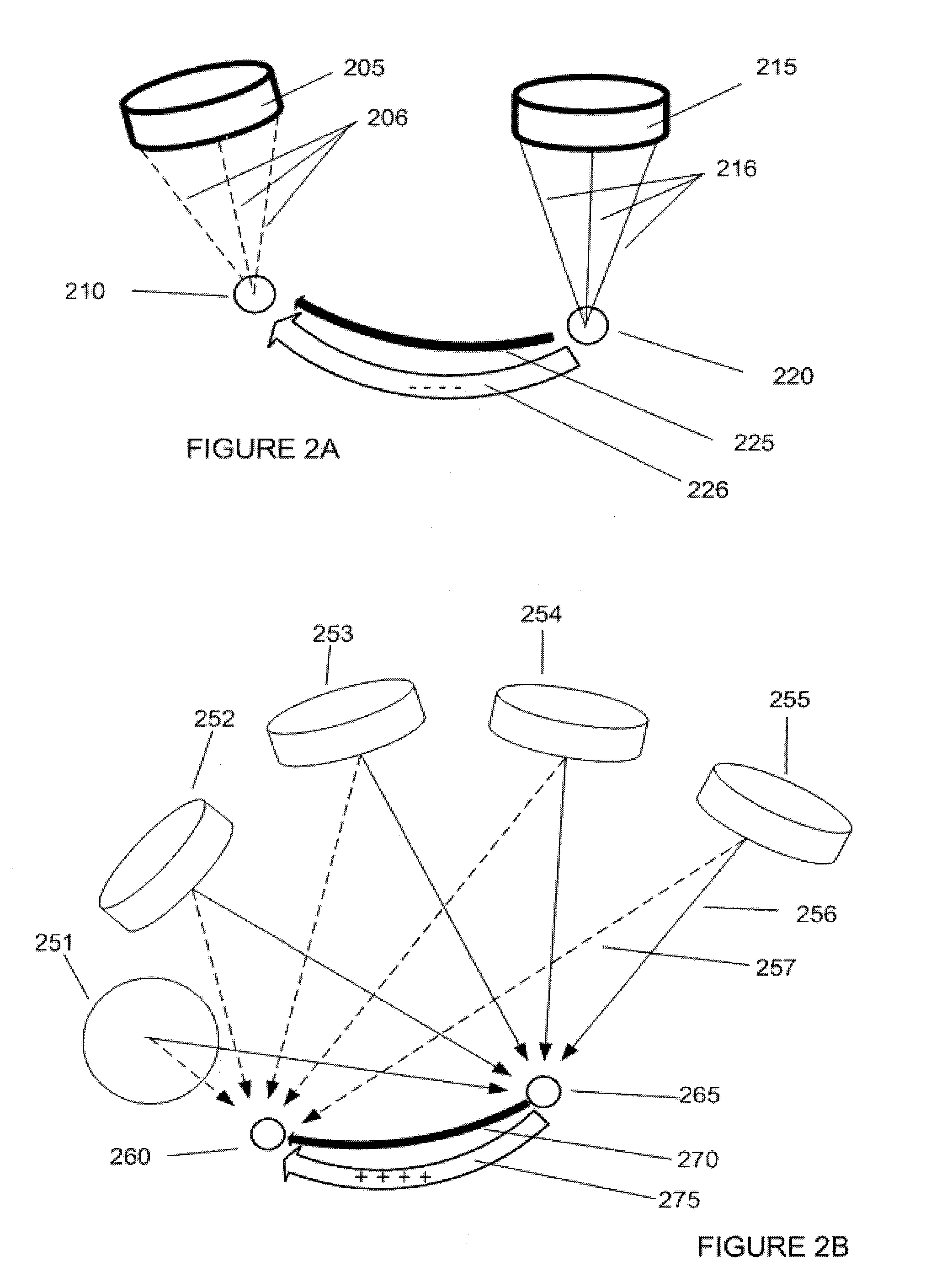
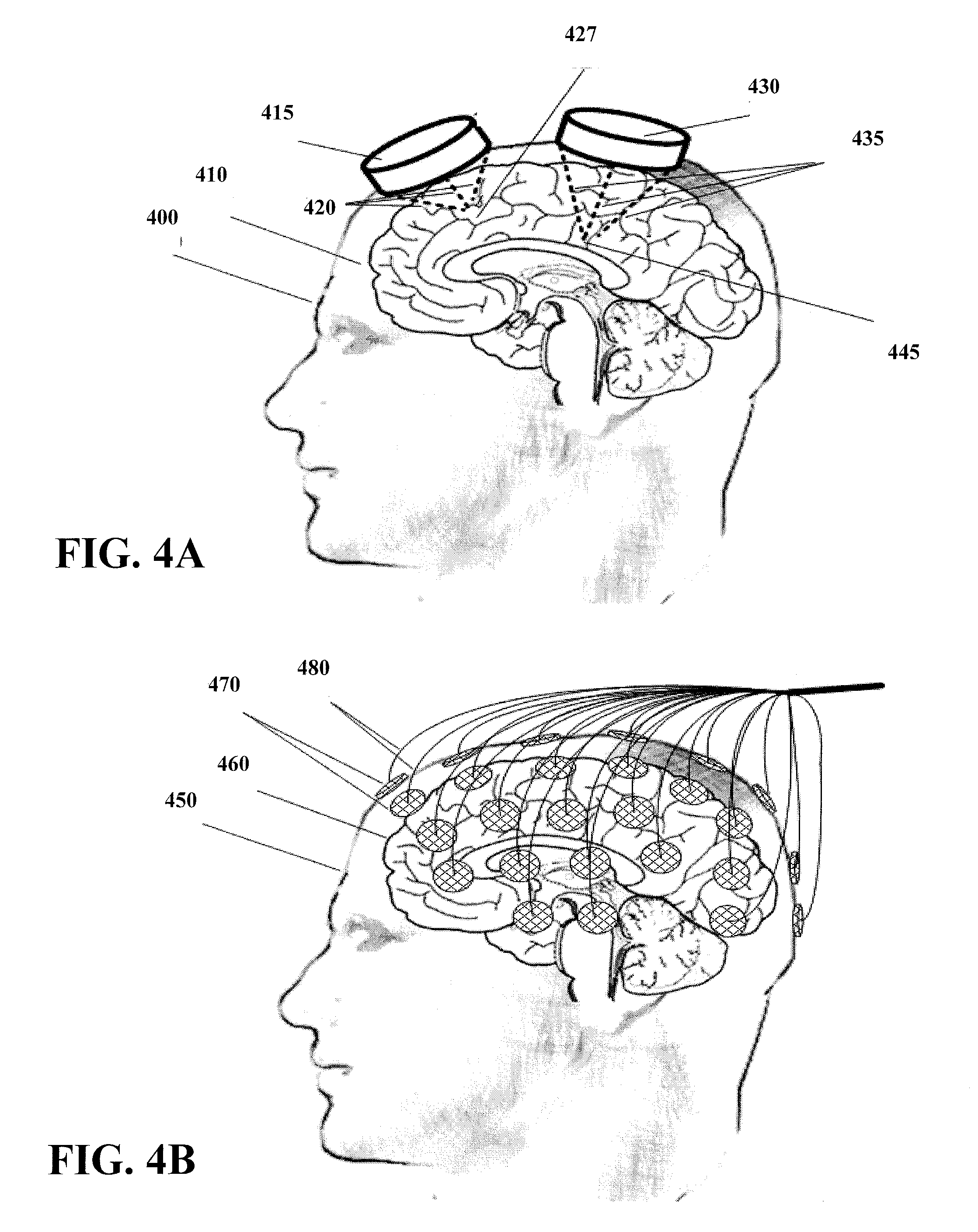
[0022] FIG. 4A shows the use of two focused-beam ultrasound transducers, each focused upon a different, but connected neural target, according to an example embodiment of the present invention; and
[0023] FIG. 4B shows an array of multiple small ultrasound transducers which may be electronically directed at one or more target regions within a patient's brain via a coordinated phase and power adjustment, also according to the present invention.
[0024] While the invention is amenable to various modifications and alternative forms, specifics thereof have been shown by way of example in the drawings and will be described in detail. It should be understood, however, that the intention is not to limit the invention to the particular embodiments described. On the contrary, the intention is to cover all modifications, equivalents, and alternatives falling within the spirit and scope of the invention.
DETAILED DESCRIPTION
[0025] The present invention is believed to be useful for enabling practical application of a variety of LTP and LTD systems, and the invention has been found to be particularly suited for use in systems and methods dealing with generating LTP or LTD effects in neural circuits through the use of sounds waves (which may include high-intensity focused ultrasound), radio frequency (RF) transmissions, electrical current, magnetic fields or ionizing radiation. In the context of this invention, the terms "sound" and "ultrasound" are used interchangeably. For simplicity, while the present invention is not necessarily limited to such applications, various aspects of the invention may be appreciated through a discussion of various examples using this context.
[0026] Various embodiments of the present invention are directed toward the use of ultrasound to produce LTP or LTD within a living subject. Sound waves are used to stimulate a first portion of neurons. For LTP, the sound waves are used to concurrently stimulate a second portion of neurons in a synchronous manner. For LTD, the sound waves are used to stimulate a second portion of neurons in an asynchronous manner. Sound waves provide stimulation both in terms of thermal properties and mechanical jarring. While specific embodiments and applications thereof involve sound waves being in the ultrasound frequency range, they need not be so limited. For example, aspects of the present invention can employ frequencies that are outside of the ultrasound frequency range.
[0027] In accordance with one embodiment, the present invention is directed to a method for modifying neural transmission patterns between neural structures. The method involves producing and directing sound waves or RF transmissions toward a first targeted neural structure, controlling characteristics of the sound waves or RF transmissions at the first target neural structure with respect to characteristics of sound waves or RF transmissions at the second target neural structure, and thereby modifying neural transmission patterns. In a related embodiment, a transducer produces the sound for stimulating the first neural structure and the second neural structure, and an electronically-based control circuit is used to control characteristics of the sound waves as described above to modify the neural transmission patterns between the first and second neural structures. In another related embodiment, a RF transmitter is used to produce RF transmissions and to focus the transmissions toward a first target neural structure.
[0028] In a more specific embodiment, the present invention uses High-intensity Focused Ultrasound (HIFU) as a powerful ultrasound emitter. In connection herewith, ultrasound waves are aimed and focused at a targeted depth geometrically, for example, by using a lens at the emitting end, or by using a curved transducer portion (e.g., a partial sphere). Ultrasound may also be aimed and focused electronically, by coordinating the phase and intensity of individual transducer elements within an array, thereby steering the location of greatest intensity, and even correcting for transmission distortions created, for example by inhomogeneities in the skull. As an ultrasound wave travels through tissue, the mechanical excitation of the tissue generates heat. Thus, the focal point of a HIFU system may be heated substantially in response to the ultrasound. Excessive heat may cause cell damage or even cell death. The threshold for cell death is generally bringing the targeted tissue to 56 degrees Celsius for one second, or 52 degrees Celsius for a longer period of time. Also, tissues held above 43 degrees Celsius for more than an hour or so may have their physiological processes (including cell division) interrupted. Accordingly, to change the firing patterns of targeted neurons, the temperature can be raised to a more moderate temperature above the normal 37 degrees Celsius. In another example, the targeted neurons may be raised to 40-42 degrees Celsius for repeated, brief periods of time, resulting in an increased spontaneous firing rate, and enabling one step of the LTP/LTD induction process.
[0029] For further information on the use of such HIFU, and related systems, reference may be made to various literature including, for example, U.S. Pat. No. 4,616,231, filed on Mar. 26, 1984 to Autrey et al. and entitled "Narrow-band beam steering system," U.S. Pat. No. 4,865,042, filed on Aug. 8, 1986 to Umemura et al. and entitled "Ultrasonic irradiation system," U.S. Pat. No. 5,520,188, filed on Nov. 2, 1994 to Hennige et al. and entitled "Annular array transducer," U.S. Pat. No. 7,175,596 filed on Oct. 29, 2001 to Vitek et al. and entitled "System and method for sensing and locating disturbances in an energy path of a focused ultrasound system," U.S. Pat. No. 6,805,129 filed on Oct. 27, 2000 to Pless et al. and entitled "Apparatus and method for ablating tissue," and U.S. Pat. No. 6,506,154 filed on Nov. 28, 2000 to Ezion et al. and entitled "Systems and methods for controlling a phased array focused ultrasound system," each of which is fully incorporated herein by reference. An MRI guided approach to beam aiming with improved phase adjustment focusing techniques incorporates stereotactic capabilities into HIFU. Some of the focused ultrasound systems have shown effectiveness for accurately targeting small lesions within the brain, thermally destroying the targeted tissue, and leaving surrounding tissue unharmed. A few devices allow for the destruction of brain tumors in a non-invasive manner (i.e., through an intact skull).
[0030] According to yet another embodiment of the present invention, HIFU is used to stimulate two different areas of the brain. The stimulation of each area is coordinated in order to facilitate the development of either LTP or LTD between the two different areas of the brain. For example, each of the areas can be stimulated in a synchronous fashion to produce LTP. If the stimulation results in an increased rate of depolarization of the neurons, the probability that both areas of the brain will fire at the same time is likewise increased. Moreover, LTP may be developed where the stimulation results in one of the areas generating action potentials more readily in response to stimulus from the other area (e.g., by having a lower depolarization threshold). In order to produce LTD, the areas may be stimulated in an asynchronous fashion to produce an increased probability of the different areas firing independently from one another.
[0031] In accordance with the present invention, it has been discovered that not all neurons react in the same fashion to temperature variations. For instance, some neurons increase their firing rate in response to a decrease in temperature and such a response impacts expected efforts in developing LTP or LTD. According to certain embodiments of the present invention, temperature data regarding these neuron-regions are used in developing LTP or LTD between the areas of the brain. In a particular instance, an area of the brain containing neurons that increase their rate of fire due to the stimulation is targeted, and at the same time, another area of the brain containing neurons that decrease their rate of fire due to stimulation is also targeted. This may be particularly useful for facilitating LTD between the targeted areas.
[0032] For further information on the use of RF transmitters to elevate temperatures of target cells, reference can be made to Kato H., Ishida T. "Present and future status of noninvasive selective deep heating using RF in hyperthermia" Med Biol Eng Comput. 1993 Jul.; 31 Suppl:S2-11 and to Gelvich E A, Mazokhin V N "Contact flexible microstrip applicators (CFMA) in a range from microwaves up to short waves" IEEE Trans Biomed Eng. 2002 Sept.; 49(9):1015-23), which are fully incorporated herein by reference. For simplicity, much of the discussion is limited to ultrasound energy; however, the invention is not so limited. For instance, it should be apparent that for many applications the use of RF frequency energy could be used in place of ultrasound energy. Whether by ultrasound, radio frequency energy, or other stimuli, neural effects of the delivered stimulus may be produced by induced temperature alteration, electrical stimulation, or by mechanical perturbation.
[0033] FIG. 1 shows a system for altering neural patterns between two groups of cells, according to an example embodiment of the present invention. Ultrasound (or RF) source 104 focuses the ultrasound (or RF) 106, 108 at locations 110 and 114. In some instances, the ultrasound can be focused at only one of the locations, or at one location at a time (e.g., for developing LTD). Control 102 controls the ultrasound produced by ultrasound source 104. In a particular instance, control 102 is responsive to input from monitor device 116. The stimulation from sound (or RF) 106, 108 can be used to effect (e.g., facilitate or frustrate through LTP or LTD) a pathway 112 between locations 110 and 114.
[0034] Ultrasound source 104 can be implemented using a number of different techniques and mechanisms. According to one embodiment, ultrasound source 104 is implemented using one single transducer for each of location 110 and 114. Such a transducer acts as a lens to focus the ultrasound waves at a point in space. The control 104 can modify various aspects of the transducer including, but not limited to, direction of focus, distance from the target location, strength of the ultrasound waves or the frequency of the ultrasound waves. Such aspects allow for precise aiming of the focal point of the ultrasound waves. This can be particularly useful for reducing unintended stimulation of cells while increasing stimulation at the target location. In some instances, the transducers can be aimed using piezoelectric devices. Piezoelectric devices allow for minute movements of the transducers in response to electrical signals.
[0035] According to another embodiment, ultrasound source 104 is implemented using an array of transducers. In one instance, the array can be implemented as one or more two-dimensional arrays of transducers. In another instance, the array can be implemented using a three-dimensional array, such as an array placed upon the skull of a patient. Similar to the single transducer implementation, the control 104 can modify various aspects of the transducers. In one instance, the transducers are similar to those used by the single transducer implementation in that they function to focus the ultrasound waves at a point in space. The array provides a summation of the effects from the transducers in order to further focus ultrasound waves. In one instance, each transducer can be individually calibrated so as to focus the ultrasound waves at the desired location. Control 104 can then alter the phase of each transducer such that the ultrasound waves provide constructive interference rather than destructive interference so as to increase the effectiveness of the delivered ultrasound energy. In another instance, the individual transducers of the array of transducers offer little directional or focusing effect when used in isolation. Control 104 modifies the aspects of the ultrasound waves of the array so as to effectively focus the ultrasound waves at the target location.
[0036] In various embodiments of the invention, control 104 can use monitoring device 116 to determine the appropriate aspects for the transducer(s). For instance, monitoring device 116 may be implemented using, for example, the ExAblate.RTM. system (InSightec Ltd. Haifa, Israel). The input from such device provides a determination as to the effectiveness of the current settings of transducer(s).
[0037] Although not shown, various embodiments of the invention may also be implemented using devices or methods to effectively determine the target location. These implementations can be particularly useful for providing improved accuracy of the ultrasound waves by precisely targeting the desired location. An example of a possible targeting method and system includes the targeting system of the ExAblate .RTM. (InSightec Ltd. Haifa, Israel). Alternatively, the system may be targeted by registering the ultrasound probes to a commercially available user-configurable tool or "universal tool" on a neuronavigation system such as the StealthStation by the Surgical Navigation Technologies division of Medtronic, Inc. (Minneapolis, Minn.). Targeting may also be achieved by affixing ultrasonic transducers to a stereotactic frame, and moving them into correct targeting position via frame-based techniques, such as those used for neurosurgery.
[0038] The display of the effect at the target may be augmented with a registration and display of calculated or measured temperature at the target site, or a measurement or calculation of neuronal activity at the target site. Temperature displays, e.g., obtained from thermal tomography systems, may be derived from measured values or from projected/calculated values. Examples of measurements and display of neuronal activity include multichannel EEG (for example Brain Electrical Activity Monitoring or BEAM) or mangetoencephalography (MEG).
[0039] FIG. 2A shows the use of two focused-beam ultrasound transducers physiologically suppressing the connection between the two regions by virtue of a mechanism such as long-term depression (LTD). An ultrasound transducer 205 delivers ultrasound energy to neural target 210 via ultrasound vectors 206. Ultrasound transducer 215 also delivers energy to neural target 220 via ultrasound vectors 216. Neural target 220 is connected to neural target 210 via neuronal tract 225. As target 220 and target 210 are stimulated in a slow-pulse rate, asynchronous fashion, long-term depression (LTD) process 226 is initiated within tract 225. The presence of LTD makes tract 225 less excitable than it would be under normal circumstances. In many instances, such a depressed excitability level is maintained for a period of weeks. Conversely, LTP may be induced with these focused-beam transducers by changing to a more rapid, regular and strong pulse pattern.
[0040] FIG. 2B shows the use of an electronically focused ultrasound transducer array to physiologically augment the connection between the two regions by virtue of a mechanism such as LTP, according to an example embodiment of the present invention. Neural target 265 is connected via neural tract 270, to neural target 260. Ultrasound transducers 251, 252, 253, 254 and 255 contribute to the total energy delivered to both neural target 260 (via dashed lines 257) and to neural target 265 (via solid lines 256), by virtue of electronic focusing techniques. Neural target 265 and target 260 are stimulated in a rapid and regular fashion to initiate an LTP process 275 within tract 270. In a specific example, the target areas are regularly pulsed at a rate of 1 Hz or more, or mildly heated at the same time thereby increasing the neuronal firing rate in tract 270. This allows for the creating of LTP, or enduring enhancement of the stimulation, along tract 270. The presence of LTP increases the excitability level of tract 270 relative to normal circumstances. In certain instances, such an increased excitability level can be maintained for a period of weeks. Conversely, LTD may also be produced with this electronically focused transducer array by changing to a weaker, slow, asynchronous pattern of pulsing.
[0041] FIG. 3A shows a specific application of the present invention in which LTP is facilitated within the "trisynaptic circuit" of the human hippocampus according to an example embodiment of the present invention. In the trisynaptic circuit, cerebral cortical regions (not shown) have connections 310 to entorhinal cortex 315. Entorhinal cortex 315 is connected to CA3 field 320 via connection 317. CA3 field 320 relays signals to CA1 field 325, via connection 322. CA1 field 325 relays back to entorhinal cortex 315 via connection 327. Finally, entorhinal cortex 315 relays data back to cerebral cortex regions via connections 310. When rapid and strong stimulations are applied to entorhinal cortex 315, long-terra potentiation (318) is established along connection 317 between entorhinal cortex 315 and CA3 field 320. Moreover, it is believed that the application of stimulation to both entorhinal cortex 315 and CA3 field 320 may improve the speed at which the LTP effect is created and also improve the length that the LTP effect is sustained.
[0042] FIG. 3B shows the use of the present invention, (in a form similar to that shown in FIG. 2B) to produce LTP between the entorhinal cortex and the CA3 fields of a human hippocampus, as can be used to augment the encoding of memory. Specifically, entorhinal cortex 375 is connected to CA3 field 380 (same as 315 and 320, respectively, in FIG. 3A). Ultrasound transducers 351, 352, 353 and 354 are arranged around a patient's scalp 360 in order to stimulate both the CA3 field 380 (via dashed lines 366) and the entorhinal cortex 375 (via solid lines 365), by virtue of electronic focusing techniques. By stimulating the entorhinal cortex 375 and CA3 field 380 in a rapid and regular fashion, a LTP process 318 is initiated within connecting tract 317 as shown in FIG. 3A.
[0043] FIG. 4A shows the use of two focused-beam ultrasound transducers, each focused upon a different, but connected neural target, according to an example embodiment of the present invention. Transducer 415 and 430 each focuses ultrasound waves 420 and 435, respectively, to specific points within the brain 410 of patient 400. More specifically, transducer 415 focuses the ultrasound to target point 427 and transducer 430 focuses the ultrasound at target point 445.
[0044] The focus points of the transducers can be controlled by modifying direction of the ultrasound waves 420 and 435. For instance, transducers having different curvatures may be used to provide different depths of convergence. Likewise, the transducer's position on the skull and distance therefrom can be modified to set the convergence point within the brain 410. The direction of the ultrasound waves can be modified by controlling the angle of the transducers 415 and 430 relative to brain 410. This can be accomplished using a variety of approaches. One such approach involves setting the angle using a structure that supports the transducers and allows for adjustment of the angle. The patient's skull can then be immobilized relative to the structure. Another approach involves attaching the transducers directly to the patient's scalp, skull, or by surgically implanting them upon or within the brain itself. The angle may be set accordingly.
[0045] FIG. 4B shows the use of an array of multiple small ultrasound transducers which may be electronically focused upon one or more targets within a patient's brain by virtue of a coordinated phase and power adjustment to the transducers in the array, according to an example embodiment of the present invention. An array of transducers 470 is attached to patient 450 for the purpose of stimulating brain 460. Individual control of the transducers is provided through communication connections 480, which are shown as wires in FIG. 4B. Examples of suitable communications connections include electrical wires, wireless transmissions and optical fibers. In some instances, power is delivered to transducers 470 through the same (or similar) connections.
[0046] According to one embodiment of the invention, the power, frequency and phase of the transducers can be modified to pinpoint the desired target locations. The delay from the time that the ultrasound wave is first transmitted to the time the ultrasound wave arrives at the target location may vary from transducer to transducer (e.g., due to differences in the location and orientation of the transducers). For instance, the distance and type of tissue can directly affect the propagation time of the ultrasound wave. A control device can compensate for differences between the transducers to ensure that the ultrasound waves add to the power of the stimulation at the desired location. In some instances, one or more of the transducers may not provide any appreciable addition to the amount of stimulation at the target location. In other instances, one or more of the transducers may create undesirable effects, such as stimulation of areas other than the target locations. For such instances, the transducer power may be reduced or removed completely. The ineffectiveness of a few of such transducers may be offset by increasing the power of the other transducers or by providing a sufficiently large array of transducers. Other variations are possible including grouping control of a number of transducers together rather than individually controlling each transducer. This may be particularly useful for reducing the complexity of the communications and the complexity of various control parameters.
[0047] Once the selected phase, frequency and other constraints are set, the transducers can be used to stimulate two different target areas in a synchronous or asynchronous manner to produce LTP or LTD, respectively, between the different target areas. The invention need not be limited to only two target areas. For instance, three or more areas of the brain may be stimulated for the purposes of facilitating LTP or LTD therebetween. In another instance, a number of different target areas may be sequentially stimulated to produce an LTP communication pathway of related target areas. Similarly, a sequence of different target areas may be stimulated to disrupt a communication pathway by producing LTD between the sequential target areas. Various combinations thereof are also possible.
[0048] In conjunction with a specific embodiment of the present invention, the thermal properties of sound waves are supplemented with electrical impulses generated by implanted devices that respond to mechanical motion produced by the sound waves. For instance a device, implanted surgically in proximity to a group of neurons that one wishes to affect, electrically stimulates those neurons when in receipt of sound waves.
[0049] In one such embodiment, implanted piezoelectric antennas are surgically implanted adjacent to the neural structure that is the target of the modulation. Such antennae produce electrical current via the piezoelectric effect of an implanted piezoelectric generator, which is rapidly moved back and forth by externally applied ultrasound. The electric current from the piezoelectric generator serves to stimulate neurons electrically, in response to the externally applied ultrasonic waves. All other principles of synchrony and asynchrony as they apply to the induction of LTP and LTD, respectively, still hold under this paradigm. The implanted ultrasound-to-electrical current conversion device serves to enhance the same processes as previously described herein. For further information regarding implanted piezoelectric antennas, reference may be made to recent publications including, for example, Wang X, Song J, Liu J, Wang Z L, in Direct-current Nanogenerator Driven By Ultrasonic Waves, Science, 2007, Apr. 6-316(5821):102-5, which is fully incorporated herein by reference.
[0050] In another embodiment of the present invention, such implantable devices can be implemented as the primary source of stimulation (e.g., with minimal thermal heating).
[0051] The various embodiments described above are provided by way of illustration only and should not be construed to limit the invention. Based on the above discussion and illustrations, those skilled in the art will readily recognize that various modifications and changes may be made to the present invention without strictly following the exemplary embodiments and applications illustrated and described herein. For instance, such changes may include variations in the duration and frequency of the stimulation between target areas. Such modifications and changes do not depart from the true spirit and scope of the present invention, which is set forth in the following claims.
* * * * *
D00000
D00001
D00002
D00003
D00004
XML
uspto.report is an independent third-party trademark research tool that is not affiliated, endorsed, or sponsored by the United States Patent and Trademark Office (USPTO) or any other governmental organization. The information provided by uspto.report is based on publicly available data at the time of writing and is intended for informational purposes only.
While we strive to provide accurate and up-to-date information, we do not guarantee the accuracy, completeness, reliability, or suitability of the information displayed on this site. The use of this site is at your own risk. Any reliance you place on such information is therefore strictly at your own risk.
All official trademark data, including owner information, should be verified by visiting the official USPTO website at www.uspto.gov. This site is not intended to replace professional legal advice and should not be used as a substitute for consulting with a legal professional who is knowledgeable about trademark law.