Reading Stand
Hernandez; Luis E.
U.S. patent application number 16/040490 was filed with the patent office on 2019-01-24 for reading stand. The applicant listed for this patent is Luis E. Hernandez. Invention is credited to Luis E. Hernandez.
| Application Number | 20190021488 16/040490 |
| Document ID | / |
| Family ID | 65014200 |
| Filed Date | 2019-01-24 |


| United States Patent Application | 20190021488 |
| Kind Code | A1 |
| Hernandez; Luis E. | January 24, 2019 |
Reading Stand
Abstract
The present invention is a novel support mechanism to support reading materials and electronic media in an elevated position, oriented towards the viewer or reader of such materials. The invention is comprised of a base board that provides the bottom support for the entire invention and serves as a base level support of a book or electronic pad. The base board contains an upper surface and a bottom surface and is further comprised of two sections, the rear section and the forward section. The rear section provides support for the hold board. The forward section provides support for the hinge board, when the hinge board is fully folded. The upper surface of the forward section contains spaced grooves which accept the bottom edge of the object being supported on the hinge board and keep it from sliding toward the forward edge of the base board.
| Inventors: | Hernandez; Luis E.; (North Bergen, NJ) | ||||||||||
| Applicant: |
|
||||||||||
|---|---|---|---|---|---|---|---|---|---|---|---|
| Family ID: | 65014200 | ||||||||||
| Appl. No.: | 16/040490 | ||||||||||
| Filed: | July 19, 2018 |
Related U.S. Patent Documents
| Application Number | Filing Date | Patent Number | ||
|---|---|---|---|---|
| 62534215 | Jul 19, 2017 | |||
| Current U.S. Class: | 1/1 |
| Current CPC Class: | A47B 23/043 20130101; A47B 23/044 20130101; A47B 2220/0077 20130101; A47B 2220/0016 20130101 |
| International Class: | A47B 23/04 20060101 A47B023/04 |
Claims
1. A book support apparatus comprising; a base board having an upper surface and a lower surface, said upper surface having surface elements to retain a bottom edge of an object being supported on said base board; a hold board, said hold board disposed on to of a rear portion of said base board; a hinge board said hinge board having a top surface and a bottom surface, both said stop surface and said bottom surface of said hinge board capable of supporting an object being read; the hinge board having a central protrusion area, with a rod running through the bottom of said central protrusion area terminating on either side of said central protrusion area within extension sections of said hold board; and wherein said hinge board is capable of pivoting around said rod.
2. The book support apparatus of claim 1, wherein an edge of said hinge board and an edge of said base board are flush when said hinge board is laid flat on top of said base board.
3. The book support apparatus of claim 1, wherein said surface elements are a plurality of grooves.
4. The book support apparatus of claim 3, wherein said plurality of grooves run along a width of said top surface of said base board and wherein said grooves are of various sizes.
5. The book support apparatus of claim 1, wherein said plurality of surface elements are protrusions or grooves.
6. The book support apparatus of claim 1, further comprising a cavity within said rear portion of said base board, wherein said cavity utilized to store items within said base board.
7. The book support apparatus of claim 6, wherein said cavity concealed beneath a removable cover.
8. The book support apparatus of claim 7, further comprising a rod channel in communication with said cavity.
9. The book support apparatus of claim 1, further comprising a base cover board, said base cover board disposed beneath said base board.
10. The book support apparatus of claim 9, wherein said base cover board functioning as a writing surface.
11. The book support apparatus of claim 1, wherein an angle of the hinge board with respect to said base board is variable.
12. The book support apparatus of claim 1, wherein said surface elements capable of retaining in an upright orientation items comprised of books, electronic tablets, magazines or pamphlets.
Description
CLAIM OF PRIORITY
[0001] This application claims priority to the U.S. Provisional Patent Application No. 62/534,215 filed on Jul. 19, 2017, the contents of which are fully incorporated herein by reference.
FIELD OF THE INVENTION
[0002] The present invention relates to desk accessories, namely a prop-up stand for reading books or viewing tablet screens while sitting at a desk or a table that is supporting such books or electronic tablets. The present invention is intended to prop-up the reading material thereby reducing eye stress and increasing the overall enjoyment of the reading experience.
BACKGROUND OF THE INVENTION
[0003] Desks are created with flat surfaces. The purpose of this is to provide a secure and spill free support surface for objects placed on a desk. For example, liquids require perfectly level support surface to avoid spillage. Stacks of papers and other objects would topple, creating a bedlam on the floor and on seating areas. However, for reading or reviewing a printed or electronic matter, it is advantageous to have the materials oriented substantially towards the user to improve focus and reduce glare from overhead lighting. Another advantage of a reading stand is the ability to keep reading material at an optimal angle toward the reader without the reader having to use his or her hands to maintain such angle.
[0004] Pulpits that are placed on desks to serve as supports for reading materials have long been known in the art. Such pulpits feature a flat surface that is tilted in the direction of the user, the bottom edge of which is terminated by a flange to prevent whatever material being supported on said pulpit from sliding off of the flat surface. Usually a pair of sidewalls or a proprietary stand supports such flat surface.
[0005] One common problem with pulpits or lecterns known in the art is that the tilted surface is usually bulky and not easily stowed while not in use. It is also of very little utility outside of its intended use.
[0006] Another disadvantage of prior art pulpits is that the tilt is often non-adjustable and the flange that stops the reading material from sliding off the top surface also obstructs the bottom edge of the object being supported, thereby preventing an unobstructed and convenient turning of pages.
SUMMARY OF THE INVENTION
[0007] The present invention is a novel support mechanism to support reading materials and electronic media in an elevated position, oriented towards the viewer or reader of such materials. The invention is comprised of a base board that provides the bottom support for the entire invention and serves as a base level support of a book or electronic pad.
[0008] The base board contains an upper surface and a bottom surface and is further comprised of two sections, the rear section and the forward section. The rear section provides support for the hold board. The forward section provides support for the hinge board, when the hinge board is fully folded. The upper surface of the forward section contains spaced grooves which accept the bottom edge of the object being supported on the hinge board and keep it from sliding toward the forward edge of the base board.
[0009] The bottom surface of the base board may contain an additional cover board, or the cover board may be integrated with a cover board surface. The cover board would either provide an additional frictional coefficient to reinforce the static nature of the base board on top of a supporting surface, such as a tabletop, or may contain soft, felt like surface, to prevent scratches on the table top used to support the present invention. The cover board may also be used as a writing surface or as a surface to support objects, such as a phone a coffee mug or reading glasses. There may also be a combination of frictional and scratch proof surfaces along the bottom face of the base cover board.
[0010] The top section of the present invention is comprised of the hinge board and the hold board. The hold board is mounted on the rear section of the base board contains a pivot rod that anchors the hinge board and enables the hinge board to be elevated up or folded down. The hold board may contain utility compartments, such as a niche for a writing utensil, a stylus or a compartment for reading glasses.
[0011] The hinge board's angle of rotation is terminated by the hold board after approximately 115.degree. degrees of rotation. When folded down, the hinge board covers all of the exposed top surface of the forward section of the base board. There is a hinge channel along the rear edge of the hinge board which is used as a sleeve around the rod. The top surface of the hinge board may also be used as a writing surface or as a surface to support objects, such as a phone a coffee mug or reading glasses.
BRIEF DESCRIPTION OF THE DRAWINGS
[0012] FIGS. 1A, 1B and 1C are perspective top view of the present invention with a deployed hinge board.
[0013] FIG. 2 is an exploded diagram of the preferred embodiment of the present invention.
[0014] FIG. 3A is a view of the front edge of the completely folded preferred embodiment.
[0015] FIGS. 3B and 3C are side-view figures of the invention depicted in FIG. 3A, demonstrating hinge board in a closed and open position.
[0016] FIGS. 4A and 4B demonstrate a base cover board.
[0017] FIG. 5 is a top view of the upper section of the present invention.
[0018] FIG. 6A is a diagram of the top surface of the base board.
[0019] FIGS. 6B and 6C are side-view diagrams of the base board of the present invention.
[0020] FIGS. 7A and 7B demonstrate the various components of the holding board.
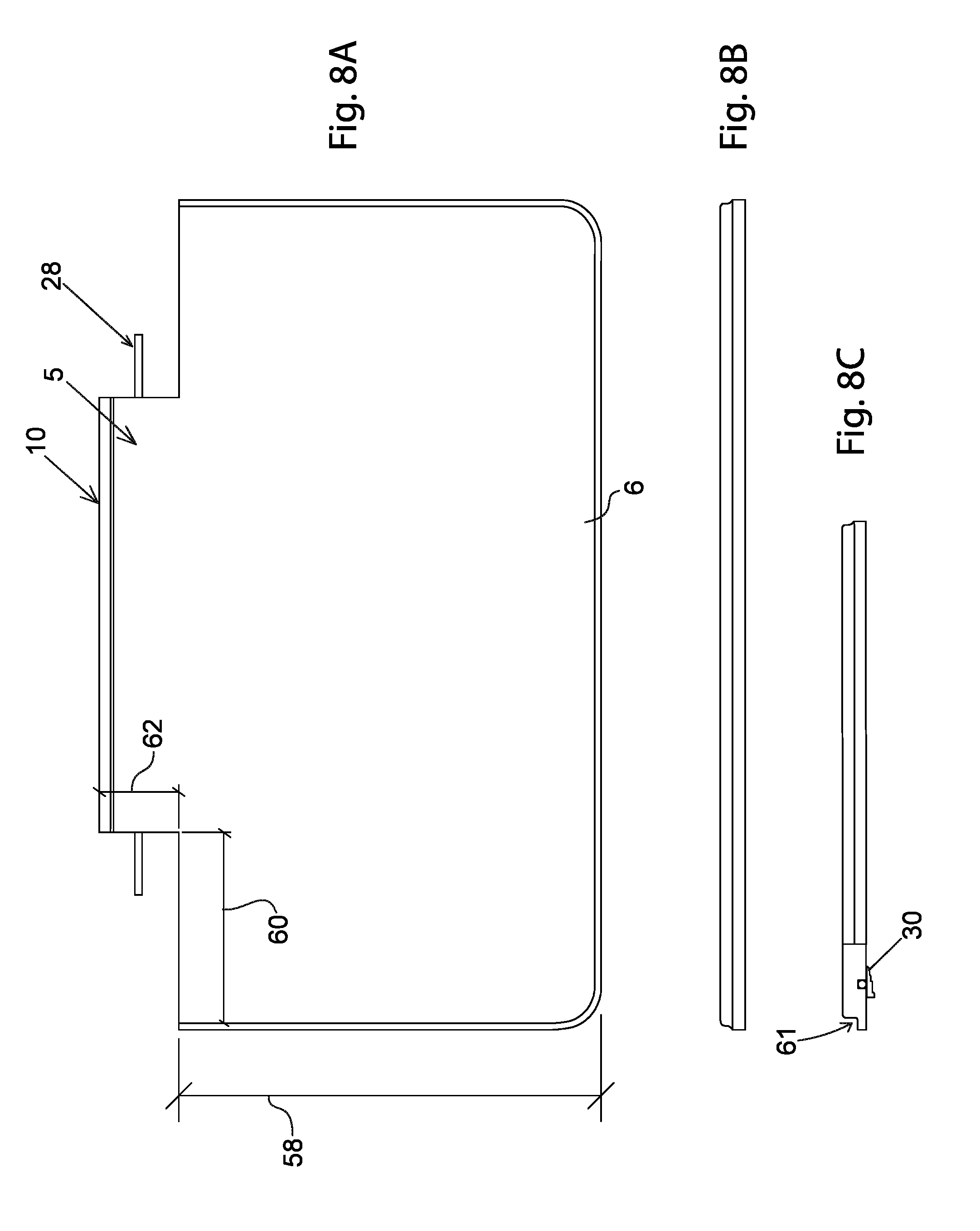
[0021] FIGS. 8A, 8B and 8C are detailed view of the hinge board.
DESCRIPTION OF THE PREFERRED EMBODIMENTS
[0022] The preferred embodiments of the present invention will now be described with reference to the drawings. Identical elements in the various figures are identified with the same reference numerals.
[0023] Reference will now be made in detail to embodiment of the present invention. Such embodiments are provided by way of explanation of the present invention, which is not intended to be limited thereto. In fact, those of ordinary skill in the art may appreciate upon reading the present specification and viewing the present drawings that various modifications and variations can be made thereto.
[0024] Turning now descriptively to the drawings, in which similar reference characters denote similar elements throughout the several views, the figures illustrate a support device 1 comprising a base board 2, a hold board 4 and a hinge board 6. The base board 2 consists of two sections a forward section 21 and a back section 23. The back section 23 supports the hold board 4 along with the pivot mechanism (items 28 and 30 FIG. 2) of the hinge board 6. The forward section 21 contains an upper surface 22. The upper surface 22 supports books and flat screen tablets that are facing or oriented toward a user of the support device 1. The grooves 20 are intended to capture the bottom edge of the object being supported. In this way only, the immediate bottom edge is retained, with pages being exposed for unobstructed perusal by a user. The groove 18 is a wider groove appearing nearly at the base 10 of the hinge board 6. While the wider groove 18 may be used to support a book or a flat screen device, it may also function to conceal a writing utensil, a stylus, reading glasses or head phones. An even wider or especially sculpted groove may be integrated with groove 18 to store a magnifying class or a place marker. Narrower groves 50 are preferably shallower than the grove 20 and are used for supporting thin pamphlets and magazines, which are not well suited for deeper grooves 20, which are made predominantly for retaining a brim of a hard-covered book, or an edge of a tablet screen.
[0025] The grooves 18, 20 and 50 run across the upper surface 22 of the forward section 21 and are positioned at least one-inch intervals from each other. However, other intervals are possible. In an alternative embodiment, protrusions instead of grooves may be employed, or a combination of grooves and protrusions may be utilized. The layout of the groves may be different, for example, groove 18 may be towards the front and one or several shallower grooves 50 may be closer to the hinge board 6.
[0026] The hinge board 6 contains the top surface 9 and a bottom surface 8. The bottom surface 8 is used to provide a backrest for books, reading matter or electronic flat screen panels, while the hinge board 6 is in the unfolded position, as shown in FIGS. 1A and 1B. The bottom surface 8 may contain rubber or silicone elements to minimize slippage or sliding while a book is being supported thereon. It may also contain lacquer, decals or backlighting elements. Similarly, the base board 2, may contain lighting elements along the forward edge 14 that would be directed at the bottom surface 8 when the hinge board 6 is fully unfolded.
[0027] The top surface 9 may similarly contain frictional elements, such as rubberized caps, to support items while the hinge board 6 is in a closed position. There may additionally be a latch along the front edge 12 of the hinge board 6 that would clip into, or lock into a loop or clasp along the front edge 14 of the base board 2.
[0028] The back section 23 preferably contains a recess cavity stylus holder 53 comprising a cavity 58. A flap 55 covers the cavity 58, for admitting a pen or stylus. A flap 55 is secured within the recess 53 with a hook and loop fastener 59. The fastener 59 may also be a snap fastener a keyhole with pin, or a resealable adhesive. It should be noted that the cavity 58 preferably contains an alcove 57a to accommodate a pin that is present with many pens and styluses. While the cavity 58 accommodates a pen or stylus, one skilled in the art may appreciate that the cavity 58 may be made sufficiently large to admit reading glasses or tissues.
[0029] FIG. 2 is an exploded diagram of the preferred embodiment of the present invention. Shown is the hinge board 6, having a center protrusion area 5, which fits between the dual extensions 13 of the hold board 4. A rod 28 traversing the center protrusion 5 via a channel along the bottom edge 10, terminates within the dual extensions 13, thereby functioning as a rod or a pivot about which the hinge board 6 is rotated. The rod holder 30 attaches along the bottom edge 10 to form a sleeve or channel for the rod 28, which is then used to rotate the hinge board 6 about the rod 28. Alternatively, a channel may be bored along the edge 10 to fulfil the structural purpose of a sleeve on a hinge. A recess 16 made through the surface of the base board 2 admits the edge 10 while edge 10 makes an arch during opening or closing. Consequently, the recess 16 corresponds to the length of the edge 10 and is sufficiently wide to accommodate the arch of the edge 10. Alternatively, the edge 10 may be sufficiently short to obviate the need for a recess 16.
[0030] Still referring to FIG. 2, shown is the recess 58 for admitting pens or styluses. The recess 58 is in direct communication with a rod channel 63, which is used to extract pens or styluses that have been wedged in or which are too thick to fit within the recess 58. The rod channel 63 allows a small rod to be inserted to push out and expel objects suck with the recess 58. Also shown is the base board 2 that is mounted onto a base cover board 32 via an adhesive surface 35. The base board 2 may function as a cushion for the base board 2 or as a way to provide addition frictional elements to immobilize the base board 2 on top of a support surface. The perimeter 34 of the base cover board 32 is preferably flush with the edge 14.
[0031] FIGS. 3A-3C demonstrate the preferred side dimensions of the present invention.
[0032] FIG. 3A is a front view showing the forward edge 14 of the base board 2 and a forward edge 12 of the hinge board 12. The preferable combined thickness 43 of the base board 2 and the hinge board 6 is one and 5/16.sup.th of an inch, which is distributed between the thickness 40 of the hinge board 6 at 1/2 inch and the thickness 42 of the base board 2 at 3/4 of an inch. The tapered perimeter 19 of the forward section 21 provides for a finger hold to lift the hinge board 6 into an open position.
[0033] FIG. 3B is a side view of the present invention with the hinge board 6 in an unfolded position. When unfolded, the hinge board forms an obtuse angle 44 of approximately 115.degree. with respect to the plane of the base board 2. The angle 44 may be varied, for example with retention washers being placed around the rod 28, which would suspend the hinge board 6 at a desired angle 44. In FIG. 3 the hinge board 6 is fully folded. The combined lengths of the hold board 4 and the hinge board 6 is equal the length of the base board 2. The section of the base board 2 covered by the hold board 4 is the rear section 23, while the forward section 21 of the base board 2 is covered by the hinge board 6.
[0034] The preferred width 46 of the present invention is approximately 11.5 inches as illustrated in FIG. 7A. of the width 46, the width 47 of the extensions 13 on either side of the hold board 4 take about 2.5 inches each, with the rest taken by the gap 3 that is used to accommodate the protrusion area 5 of the hinge board 6. The dimensions of the gap 3 are preferably 6.5 inches in width and 11/4 of an inch in length 49. The groove 26 is a utility compartment for storing objects, such as writing utensils, magnifying lens, reading glasses, headphones or a stylus. Also shown is the terminus cavity 7 within each extension section 13 to house the rod 28. The terminus cavities 7 anchor the pivot hinge of the hinge board 6. FIG. 7B shows a front view of the hold board 4, showing the cavities 7, the edge 17 and the cavity 3.
[0035] The overall length of the base board 2 other components of the present invention is preferably up to 9 inches shown in item 52 (FIG. 4A) which is also the length of the base cover board 32. FIG. 4B shows the thickness 54 of the base cover board 32 being equal to 1/18 of an inch. The base cover board 32 may be made of plastic, steel, fabric, paper or leather. The base cover board 32 may be an integrated layer into the base board 2.
[0036] FIG. 5 is a top view of the present invention. Showing the hinge board 6, the top surface 9, the hold board 4, the extensions 13 and the groove 26. The grove 26 is preferably used to store writing utensils. The hold board 4 may contain a light with batteries or a corded light (not shown). The present invention may be manufactured out of wood, pressed wood chips (particle board), metal, metallic alloy, stone, polymeric or resinous materials, or a combination of such materials.
[0037] The top view of the base board 2 shown in FIG. 6A shows the top surface 22 having evenly spaced grooves 20, which are paced approximately 1 1/16.sup.th from each other. Each groove 20 functions as a point of retention of an edge of a book or a flat an electronic pad. The narrow width of the grooves 20, just 5/16 of an inch, coupled with the angle which a book would rest against said grooves 20, ensures that only the binding or the very bottom edge is snagged inside a groove 20, with the rest of the book exposed to unobstructed turning of pages.
[0038] Groove 18 is disposed close to a base of an opened hinge board 6 and may also be used for the same purpose as grooves 20 or may be used to store items. The recess 16 is a wider channel or groove intended to provide clearance for the pivoting bottom edge 10 of the hinge board 6. For this reason, the recess 16 is slightly longer at 7.5 inches then the width of the protrusion 5 of the hinge board 6. FIG. 6C demonstrates the lengthwise edge of the base board 2 having the edge 14 the tapered edge 19 and the rod channel 63.
[0039] FIGS. 8A and 8B demonstrate the dimensions of the hinge board 6. With the length of it preferably at 73/8.sup.th of an inch. The edge 10 contains a protrusion 5 that is formed due to sculpting a gap having dimensions of 2 17/32'' in width 60 and 1 13/22 in length 62 of the corners areas of the hinge board 6 along the bottom edge 10. FIG. 8C shows a small flange 61 along the bottom edge 10 is present to ensure that the pivoting hinge board 6 has sufficient clearance to fold and unfold.
[0040] Although dimensions above have been stated using the imperial system, it is assumed that dimensions will be substantially the same when using equivalent dimensions under the metric system. All dimensions may be changed as per preference or requirement, with other dimensions changed proportionally as necessary.
[0041] Although this invention has been described with a certain degree of particularity, it is to be understood that the present disclosure has been made only by way of illustration and that numerous changes in the details of construction and arrangement of parts may be resorted to without departing from the spirit and the scope of the invention.
* * * * *
D00000
D00001
D00002
D00003
D00004
D00005
D00006
D00007
D00008
XML
uspto.report is an independent third-party trademark research tool that is not affiliated, endorsed, or sponsored by the United States Patent and Trademark Office (USPTO) or any other governmental organization. The information provided by uspto.report is based on publicly available data at the time of writing and is intended for informational purposes only.
While we strive to provide accurate and up-to-date information, we do not guarantee the accuracy, completeness, reliability, or suitability of the information displayed on this site. The use of this site is at your own risk. Any reliance you place on such information is therefore strictly at your own risk.
All official trademark data, including owner information, should be verified by visiting the official USPTO website at www.uspto.gov. This site is not intended to replace professional legal advice and should not be used as a substitute for consulting with a legal professional who is knowledgeable about trademark law.